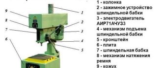
A Morse taper is an auxiliary device used to hold industrial tools. The device ensures quick change of equipment without loss of accuracy of operations. The prototype of the product was made in 1864, since then it has been successfully used in industry.
In the material:
- Current standards
- Types of shanks Shanks with claw
- Threaded shanks
- Friction-locked shanks
- Shank symbols
- Cones 7:24
Current standards
The sizes of Morse cones depend on their design. Products are available for sale in 8 standard sizes - from KM0 to KM7. The characteristics of each standard size are specified in industry standards. The specifics of compatible equipment are also displayed there.
Rice. 1 Morse taper with and without cartridge
Domestic and foreign standards regulating the manufacture of Morse cones:
- ISO 296;
- DIN 228;
- GOST 25557-2016.
Morse cones according to GOST are not available in all standard sizes. The Russian standard does not contain products belonging to the KM7 category. They have been replaced by No. 80 cones, which are incompatible with foreign-made analogues.
Torches, knocking, mirrors
Armies of many nations and eras have used columns of smoke from fires or torchlight to convey messages. Such a signal can be seen from afar, but such communication was laconic, slow and not very simple: it was necessary to agree on the meaning of the signals, and then light the fire.
Nevertheless, the ancients came up with a universal alphabet for such a clumsy medium. We know it as the Polybius square, who in his “General History” described a system for transmitting any message using torches.
In it, 25 characters of the Greek alphabet were written in a 5x5 table. Each letter corresponded to a pair of numbers, the first of which referred to the row number, and the second to the column. For example B - 12, H - 23, and so on. If you write the letters not in alphabetical order, but in random order, then you will also receive cryptographic protection for your communication channel: the message will be read only by those who have the correct table.
Polybius square for the Latin alphabet
Share
Since each letter corresponded to a pair of numbers from one to five, two sets of torches and a high platform were required to convey the message. The number of torches on the left side indicated the first digit, and on the right - the second. After some time, when the recipient wrote down a pair, the sets were changed to others indicating the next letter.
Two millennia later, after the invention of Morse code, the Polybius square continued to be used to communicate between prisoners by tapping. The knocks came in series from one to five, a pause indicating the end of the series and the transition to the next letter. Cryptography historian David Kahn writes in his book “Codebreakers” that this is how Russian political prisoners under the Tsar and American prisoners of war in Vietnam communicated in order to coordinate their testimony during interrogations and provide moral support.
Transmitting the word ALLO with torches across the Polybius square
Jonathan Martineau/Wikimedia Commons
Share
The idea of optical signaling was not lost either: the word “telegraph” itself originally referred to the semaphore of the Chappe brothers, invented at the end of the 18th century. Almost all of Europe opposed revolutionary France, and the Convention was forced to defend the republic from superior forces over a vast territory. By order of the government, a two-hundred-kilometer chain of 22 high towers was built between Paris and Lille. A system of movable bars was installed on the top of each of them, the “gestures” of which transmitted messages along the chain. The transmission of each letter took about a minute, but in the end the dispatch flew hundreds of kilometers in less than a quarter of an hour - unimaginably fast in a world of horse-drawn messengers and leisurely stagecoaches. After some time, the optical telegraph connected the entire territory of France, and it is unknown whether Napoleon would have been as successful without such information superiority.
Types of shanks
Turning Morse tapers with several types of shanks are available for sale. The elements differ in the specifics of their execution and fixation features.
Shanks with claw
The shanks with the claw are fixed by wedging. The tab fits into the corresponding groove of the spindle, ensuring reliable fastening of the component. It prevents the product from turning and greatly simplifies its removal if necessary.
Rice. 2 Morse taper with chuck and shank with claw
Threaded shanks
Threaded shanks are screwed into the spindle and securely fixed in the mounting opening. The size and type of thread are determined by the design.
Rice. 3 Morse taper with chuck and threaded shank
Friction-locked shanks
A type of shank that does not contain tabs or threads. The product is held due to frictional forces that arise from close contact between the elements of the cone and the spindle.
Rice. 4 Morse taper with cartridge, fixed by friction
Shank symbols
The shanks of Morse cones may contain symbols that determine the specifics of their design.
Internal type shank designations:
- BI – with groove;
- AI – with a hole along the axis;
- BIK – with groove and opening for coolant;
- AIK – with hole and opening for coolant.
Designation of external type shanks:
- BE – with foot;
- AE – with hole;
- BEK – with a foot and an opening for coolant;
- AEK - with thread and opening for coolant.
The Morse taper marking for machines is also indicated in the accompanying documentation.
Fastening tools using a cone
For end tools, of particular importance is the outer cone with a tab (Fig. 14, a) or with a threaded hole (Fig. 14, b), which is inserted into the corresponding seat in the chuck or directly in the machine spindle, made in the form of an internal cone. The main dimensions of the cones are indicated by letters. Fastening with a cone and claw covers tools such as twist drills, countersinks, and countersinks. Cones vary in size. The main ones are Morse cones of seven numbers.
Metric cones
According to GOST 2847-45, metric cones were additionally introduced, which have not found such wide distribution in industry as Morse cones. Their designations are taken according to the largest; (calculated) diameter D, which has the following values: 4 6, 80, 100, 120, 140, 160, 200 mm. Thus, Morse cones are located between metric cones. The taper for metric cones is set to 1:20, which corresponds to the angle of cone 2a at 2°5G51. The taper for Morse cones is different - from 1: 19.002 (for cone No. 5) to 1: 20.047 (for cone No. 2). Accordingly, the cone angle 2a is also variable. The difference in taper is explained by converting inch dimensions to millimeter dimensions. The issue of unifying cones has been long overdue, but has not yet received resolution, despite a number of proposals in this area. 1
Rice. 14. Cones for holding tools
The cone is used to transmit torque from the machine spindle to the tool. The transmission occurs as a result of the friction that occurs during the cutting process between the surfaces of the outer cone of the tool and the inner cone of the machine spindle under the action of axial force. It must be borne in mind that the torque must be transmitted exclusively by the cone without the participation of the lantern. The latter is intended only to facilitate the ejection of the tool from the spindle by means of a wedge, as indicated in Fig. 15, a. This requirement is especially important for twist drills, which operate under more difficult conditions compared to countersinks and reamers.
Calculation of the required cone
Let's consider the conditions for proper fastening of the drill.
The axial force Q can be decomposed into two forces: P - perpendicular to the surface of the cone and V - perpendicular to the axis of the drill (Fig. 15, b). A force P equal to Q/sin a causes a frictional force μP on the surface of the cone, where μ is the friction coefficient, which can be estimated at approximately 0.096.
Torque can be determined by the formula:
Where D and d are the maximum and minimum diameters of the working part of the cone.
This formula is valid provided that the angle a is accurately maintained both in the machine spindle bushing and at the drill. In practice, however, this never happens. Deviations of the angle a are always observed, since the precise production of conical surfaces (especially internal ones) is associated with great difficulties. In addition, during operation, due to careless handling, the mating conical surfaces receive additional and often quite significant errors. In this case, the foot can no longer help but take part in the transmission of torque, which leads to its breakdown. Experimental work shows a sharp decrease in the magnitude of the transmitted torque during drilling with an increase in the error in angle a (total). If the error Δа does not exceed 10 min., which is practically quite sufficient, then the value of the torque M can be expressed by the following formula, derived on the basis of experimental work:
where Δa ranges from 0-10º
For a twist drill, there is a certain relationship between torque and axial force. It is a constant value for each processed material, for example, for steel with σр = 30:110 kg/mm ratio М/Q = (0.038-0.025)d and for cast iron of medium hardness
M/Q= 0.034d, where d is the diameter of the drill.
When calculating, you should take the maximum value M/Q. In addition, it must be increased to be able to transmit torque under more unfavorable conditions, namely:
- For larger deviations in angle a (total) than indicated below;
- when the drill becomes dull, since, according to experimental data, the torque in this case increases almost 3 times, whereas
- axial pressure increases slightly;
- when chips are pinched, when the torque increases sharply;
- at the exit of the drill from the hole, when the cone is immediately unloaded, while the torque continues to increase.
Fig.15
The cone must be designed in such a way that, even in the most unfavorable cases, it can transmit torque only through friction without the participation of the claw. A threefold increase in the M/Q ratio can be accepted as quite sufficient, then it will be equal to 0.12d. This value must be substituted into the formula for M.
The total error of the mating surfaces Δa for universal-purpose drills can be estimated at +5′, of which ±2′ should be attributed to the drill cone and ±3′ for the spindle sleeve, since the inner cone is more difficult to manufacture than the outer one. Based on the given data, you can determine what maximum drill diameter corresponds to each cone number. Calculations show that for some, for example large drills, the maximum diameter does not coincide with that accepted in the standards. Therefore, if unfavorable circumstances occur, the foot will also participate in the transmission of torque, along with the conical surface, which can cause it to break. This makes it advisable to manufacture drills with two sizes of cones. Drills with a reinforced taper (one number larger) should be used for heavier work. Tool factories produce these drills with a diameter of 12 mm in accordance with GOST 889-41.
Depending on the cone number and the size of the drill, the transition section from the cone to the drill cylinder must be designed differently (Fig. 16, a). This is necessary to facilitate the exit of the grinding wheel when grinding both the working part of the drill and the cone. Drills with a diameter of 6 to 10 mm can be produced without a neck.
Type A can be replaced by a modification that has an undercut instead of a belt (Fig. 16, b).
Rice. 16. Design options for tapered tool shanks
Countersinks and reamers are designed with a transition section of type B.
GOST standards
The dimensions of cones for tools are established in accordance with GOST 2847-45, and the tolerances for them are in accordance with GOST 2848-45.
Fastening by means of a cone with a threaded hole is used for various types of end mills: cylindrical, keyed, T-shaped, etc. The threaded hole is intended for a tightening bolt passed through the hollow spindle of the machine. This design provides more reliable fastening compared to a cone with a lanyard. This is especially important for cutters with helical teeth, the direction of which coincides with the cutting direction. In the absence of a tightening bolt, the conical shank of the cutter will tend to come out of the spindle socket under the action of an axial force resulting from the presence of helical cutter teeth.
Similar materials
Shortened Morse tapers
To solve a number of production problems, the length of the classic cone is excessive. In this case, it is advisable to use shortened products. The length of such cones is 2 times less than the original one. They are quickly fixed in the spindle, allowing you to perform high-quality work in limited space.
Shortened models are proportional to the KM cones and have the corresponding designations:
- B7 – KM0 14 mm long;
- B10 – KM1 18 mm long;
- B12 – KM1 22 mm long;
- B16 – KM2 24 mm long;
- B18 – KM 2 32 mm long;
- B22 – KM3 45 mm long;
- B24 – KM3 55 mm long;
- B32 – KM4 57 mm long.
The largest cones are B45. They are a shortened version of the KM5 and are 71 mm long.
Rice. 5 Cone 7:24
Using a wide angle cutter
A fairly simple way to obtain a tapered surface on a lathe is to use a corner cutter. With its help, you can create a cone of short length; the cutting edge should be straight. The angle of the taper can be adjusted by sharpening the edge or setting it at a specific angle to the workpiece.
Turning a cone with a cutter
All of the above methods require certain skills in operating a lathe. In some cases, for large-scale production, special copiers are made. For small-scale production, a method that uses a ruler or turning the lathe slide or shifting the headstock is suitable.
Alternative solutions
Similar products have been created as a replacement for Morse tapers. They have a number of unique qualities and completely or partially replace classical solutions.
Cones 7:24
7:24 tapers are designed for machines with automated tool changing capabilities. The products do not have the disadvantages of typical cones associated with jamming, large sizes and insufficient contact of the axial stop.
Rice. 6 Cone 7:24
The products are intended for highly equipped enterprises and are manufactured in different countries. Manufacturers use different standards when producing tool cones.
- ISO 7388. International standard used by many EU companies.
- GOST 25857-2014. Domestic standard, analogue of the ISO standard. The main differences lie in the parameters of the materials used.
- DV and SK. Standards applicable in Germany.
- ANSI B15.18. Regulatory documents used by American manufacturers.
- JIS B6339. Japanese variation of instrumental cones. The dimensions of products are determined in the inch system.
- NFE 62540. Standard used by French manufacturers.
- IS 2340. Indian Standard.
When designating standard sizes of products, numbers from 10 to 80 are used. The gradation step is 5. Below is a table of the sizes of tool cones, where D is the maximum diameter of the conical opening, L is its depth, and DF is the diameter of the flange.
Table No. 2. Tool cone sizes
HSK cones
HSK type cones are designed for milling machines. Products are manufactured in accordance with GOST R 12164 and DIN 69893. Products are designated by letters from A to F, the name indicates the diameter of the flange (minimum value - 25 mm, maximum - 160 mm).
Advantages of HSK series solutions:
- the fastest possible replacement of metal-cutting tools;
- moderate weight;
- ability to work with turning-type cutters;
- excellent repeatability;
- high levels of rigidity.
To work with square cutters, adapters are required. Cutters from some manufacturers immediately have an HSK shank.
Rice. 7 HSK series products
CAPTO
CAPTO cones are positioned as a premium analogue of HSK series products. The product is manufactured in accordance with ISO 26623 and has a triangular cross-section. The angle of the landing surface is similar to classic cones. The product is securely fixed in the working opening and ensures good repeatability in various axes.
Products in the CAPTO line are optimal for roughing and semi-roughing. It provides high rigidity of the connection, which can lead to premature wear of the spindle under significant load.
There are 6 cones in the manufacturer’s model range. The products are marked from C3 to C10, the diameter of the working flange ranges from 32 to 100 mm.
Cones with taper 1:30 and 1:50
In tool making and general mechanical engineering, cones with a taper of 1:30 and 1:50 are accepted.
Taper 1:30 have holes in mounted reamers and countersinks. The conical shape of the holes in these tools is necessary for better centering and a firm fit on the mandrels. The working ends of mandrels for reamers and countersinks also have the same taper. The slope angle for a taper of 1:30 is 0° 55′.
The 1:50 taper has locating pins used when it is necessary that two parts of the machine, bolted together, cannot move relative to each other (for example, the caliper apron and its longitudinal slide).
The locating pins fit into holes drilled and reamed simultaneously in both parts after they are assembled. The taper of such pins is taken to be 1:50, which corresponds to the slope angle α = 0° 34′.
Adapters
When working with cones, adapter mandrels and adapter bushings for Morse tapers are used. They simplify the work, eliminating the purchase of additional equipment and tools.
Rice. 8 Adapter sleeve from KM2 to KM3
Experts recommend purchasing certified cones and transition elements. This will ensure high-quality work, reduce the likelihood of breakdowns, reduce production costs and costs for additional processing of workpieces.
Method of displacement relative to the axis of centers
Shifting the centers also makes it possible to obtain a Morse taper on a lathe. However, in this case, turning can only be done on external conical surfaces. The advantages of the method under consideration include:
- It is possible to make a long Morse taper.
- A mechanical support feed is used, which makes it possible to use conventional models of lathes.
Center axis offset
Significant disadvantages include:
- Low precision with which the part can be made.
- In the process of obtaining a cone, the center holes become skewed.
The amount of displacement of the tailstock during the creation of conical surfaces is determined using a right triangle.