Beam deflection calculations must be carried out for almost any structure to check its reliability and strength. Under the influence of external and internal factors and natural phenomena, the beam is subject to deformation.
The beam is compared to a rod fixed to supports. The more supports, the more difficult it is to carry out the calculation yourself. The main load is calculated by adding forces perpendicular to the section.
This calculation is the basis of strength resistance and helps determine the highest deformation. The indicator values must be within the acceptable range.
Types of beams
When constructing buildings, beams of different configurations, sizes, profiles, and cross-sectional nature are used. They are made of metal and wood. For any type of material used, an individual bending calculation is required.
Types of beams:
- Wooden
— they are used mainly in the construction of individual buildings. They are used in the construction of floors, ceilings, and load-bearing floors. Wood is a capricious material and is subject to deformation. To determine the maximum bending, the following parameters are essential: the profile used, size, load, nature of the cross section.
- Metal
— such beams are made from an alloy of metals and their cross-section is complex. Therefore, special attention is paid to the rigidity as well as the strength of the connections. Metal beams are used in the construction of high-rise buildings and structures that require high strength.
Basic provisions of calculation methods
Modern construction methods for calculating rod (beam) structures for strength and rigidity make it possible, already at the design stage, to determine the value of the deflection and make a conclusion about the possibility of operating the building structure.
Calculation of rigidity allows us to resolve the issue of the greatest deformations that can occur in a building structure under the complex action of various types of loads.
Modern calculation methods, carried out using specialized calculations on electronic computers, or performed using a calculator, make it possible to determine the rigidity and strength of the research object.
Despite the formalization of calculation methods, which involve the use of empirical formulas, and the effect of real loads is taken into account by introducing correction factors (safety factors), a comprehensive calculation quite fully and adequately assesses the operational reliability of a constructed structure or a manufactured element of a machine.
Despite the separateness of strength calculations and determination of structural rigidity, both methods are interrelated, and the concepts of “rigidity” and “strength” are inseparable. However, in machine parts, the main destruction of an object occurs due to loss of strength, while structural mechanics objects are often unsuitable for further use due to significant plastic deformations, which indicate low rigidity of structural elements or the object as a whole.
Today, in the disciplines “Strength of Materials”, “Structural Mechanics” and “Machine Parts”, two methods of calculating strength and stiffness are accepted:
- Simplified (formal), during which aggregated coefficients are used in calculations.
- Refined , where not only safety factors are used, but also contraction is calculated based on limit states.
Beam strength and rigidity
When designing, you should take into account the bending of the beams so that the structure is reliable, high-quality, durable and practical.
These parameters are influenced by the following factors:
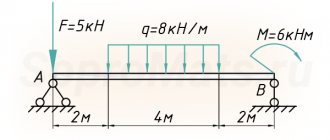
- the magnitude of external loads, their position;
- parameters, character, finding the cross section;
- longitudinal quantities;
- material;
- number of supports, method of their fastening.
There are 2 methods of calculation: simple - a magnifying factor is used, and accurate - additionally includes border calculations.
HOUSEHAND.ru -
If the deflection of the fitting shaver is increased, then during processing barrel-shaped teeth are formed on the wheels (Fig. Barrel-shaped teeth decrease (in thickness) from the middle to the ends of the wheel by 0.01 - 0.03 mm. Wheels with barrel-shaped teeth are less sensitive to misalignment of the transmission axes, ensure the position of the contact spot in the middle of the tooth, help reduce transmission noise and other disadvantages.Wheels with barrel-shaped teeth can be processed with conventional shavers, but on machines with a special device.
A feature of the calculation of these shavers is the determination of the deflection of the side surface of the teeth and the change in tooth thickness along the length of the shaver. If the deflection of the fitting shaver is increased, then during processing barrel-shaped teeth are formed on the wheels (Fig. Barrel-shaped teeth decrease (in thickness) from the middle to the ends of the wheel by 0.01 - 0.03 mm. Wheels with barrel-shaped teeth are less sensitive to misalignment of the transmission axes , ensure the position of the contact spot in the middle of the tooth, help reduce transmission noise and other disadvantages.Wheels with barrel-shaped teeth can be processed with conventional shavers, but on machines with a special device.
Factory testing of springs is usually limited to determining the spring deflection at a given operating load.
In Fig. 3 - 5 show data for determining the deflection arrow, stresses in the middle surface and bending stresses for a square plate based on the results of a refined solution; in Fig. 4 - 5 indicated: A - angle of the plate; C - center.
It should be noted that the above values of the coefficient J3 for determining the deflection of beams have limited use, because they provide an answer only for two extreme cases of securing the ends of beams - free and clamped. The frames of boiler units are a frame system with elastic seals of the crossbar (horizontal beam) in the nodes. In this case, angles of 90 are maintained between the axes of the rods converging at the node.
Pages: 1 2
Stiffness calculation
Calculation algorithm:
The formula indicates:
- M – max moment occurring in the beam;
- Wn,min – moment of resistance of the section (tabular indicator);
- Ry – bending resistance (calculated indicator);
- γc – indicator of working conditions (tabular indicator).
Such a calculation is not labor-intensive, but for a more accurate value the following is required:
- working plan of the facility;
- determination of the characteristics of the beam, the nature of the section;
- determination of the maximum load acting on the beam;
- estimation of the maximum deflection point;
- checking the strength of max bending moment.
11. Determination of the rotation angle.
(return to main content)
The deflection of a building structure, and in our case beams, is the only value that is easiest to determine experimentally and most difficult to determine theoretically. When we applied a load to the ruler (we pressed on it with our finger or the power of our intellect), we saw with the naked eye that the ruler bent:
Figure 11.1. The displacement of the center of gravity of the cross section of the beam in the center of the beam and the angle of rotation of the longitudinal axis passing through the center of gravity of the cross section on one of the supports.
If we wanted to determine the amount of deflection experimentally, then it would be enough to measure the distance from the table on which the books lie (not shown in the figure) to the top or bottom of the ruler, then apply a load and measure the distance from the table to the top or bottom of the ruler. The difference in distances is the desired deflection (in the photograph, the deflection value is indicated by an orange line):
Photo 1.
But let's try to come to the same result, following the thorny path of the theory of strength of strength.
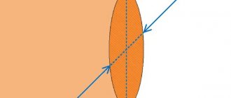
Since the beam bent (in the good sense of the word), it turns out that the longitudinal axis, passing through the centers of gravity of the cross sections of all points of the beam, and which coincided with the x , has shifted. This displacement of the center of gravity of the cross section along the y-axis is called beam deflection f . In addition, it is obvious that on the support this very longitudinal axis is now at a certain angle θ to the x , and at the point of action of the concentrated load the angle of rotation = 0, since the load is applied in the middle and the beam bent symmetrically. The angle of rotation is usually denoted by “ θ ”, and the deflection “ f ” (in many reference books on strength materials, the deflection is denoted as “ ν ”, “ w ” or any other letters, but for us, as practitioners, it is more convenient to use the designation “ f ”, adopted in SNiPs ).
We don’t yet know how to determine this very deflection, but we do know that the load acting on the beam creates a bending moment. And the bending moment creates internal normal compressive and tensile stresses in the cross sections of the beam. These same internal stresses lead to the fact that in the upper part the beam is compressed, and in the lower part it is stretched, while the length of the beam along the axis passing through the centers of gravity of the cross sections remains the same, in the upper part the length of the beam decreases, and in the lower part it increases, Moreover, the further the cross-sectional points are located from the longitudinal axis, the greater the deformation will be. We can determine this very deformation using another characteristic of the material - the elastic modulus.
If we take a piece of bandage rubber and try to stretch it, we will find that the rubber stretches very easily, and, scientifically speaking, deforms by a significant amount when exposed to even a small load. If we try to do the same with our ruler, it will hardly be possible to stretch it even tenths of a millimeter with our hands, even if we apply a load tens of times greater to the ruler than to the bandage rubber. This property of any material is described by Young's modulus, which is often simply called the elastic modulus. The physical meaning of Young's modulus at the maximum permissible load of the structure being calculated is approximately the following: Young's modulus shows the ratio of normal stresses (which, at the maximum permissible load, are equal to the calculated resistance of the material to relative deformation under such loading:
E = R/Δ (11.1.1)
and this means that for the material to work in the region of elastic deformations, the value of internal normal stresses, acting not in the abstract, but on a well-defined cross-sectional area, taking into account the relative deformation, should not exceed the value of the elastic modulus:
E ≥ N/ΔS (11.1.2)
in our case, the beam has a rectangular cross-section, so S = b h , where b is the width of the beam, h is the height of the beam.
Young's modulus is measured in Pascals or kgf/m2. For the vast majority of building materials, elastic moduli are determined empirically; you can find out the value of the modulus for a particular material using a reference book or a summary table .
Determining the amount of deformation for a cross section subject to a uniformly distributed load or a concentrated force at the center of gravity of the cross section is very simple. In such a section, normal compressive or tensile stresses arise, equal in value to the acting force, directed oppositely and constant over the entire height of the beam (according to one of the axioms of theoretical mechanics):
Figure 507.10.1
and then it is not difficult to determine the relative deformation if the geometric parameters of the beam (length, width and height) are known; the simplest mathematical transformations of formula (11.1.2) give the following result:
Δ = Q/(S E ) (11.2.1) or Δ = q h/(S E ) (11.2.2)
Since the calculated resistance shows what maximum load can be applied to a certain area, in this case we can consider the effect of a concentrated load on the entire cross-sectional area of our structure. In some cases, it is important to determine the deformations precisely at the point of application of a concentrated load, but we are not considering these cases now. To determine the total deformation, you need to multiply both sides of the equation by the length of the beam:
Δl = Q l/(b h E) (11.2.3) or Δl = q h l/(b h E) (11.2.4)
But in the case we are considering, the cross sections of the beam are acted not by a concentrated force applied to the center of gravity of the cross section, but by a bending moment, which can be represented in the form of the following load:
Figure 149.8.3
With such a load, the maximum internal stresses and, accordingly, the maximum deformations will occur in the very top and bottom parts of the beam, and in the middle there will be no deformations. We found the resultant for such a distributed load and the shoulder of the concentrated force in the previous part (), when we determined the moment of resistance of the beam. Therefore, now we can easily determine the total deformation in the uppermost and lowermost parts of the beam:
Δх = M x/((h/3) b (h/2) E) (11.3.1)
or
Δх = M x/(W E) (11.3.2)
since W = b h2/6 (10.6)
We can obtain the same formula in another way. As we know, the moment of resistance of the cross section of the beam must satisfy the following condition:
W ≥ M/R (10.3)
If we consider this relationship as an equation and replace the value of R in this equation with ΔE, we obtain the following equation:
W = M / ΔE (11.4.1)
And then:
M = WΔE (11.4.2) a Δ = M/(W E) (11.4.5) and, accordingly, Δx = M x/(W E) (11.3.2)
As a result of the deformation we just defined, our beam could look like this:
Figure 11.2. Estimated (for clarity) beam deformation
that is, as a result of deformations, the highest and lowest points of the cross section will shift by the amount Δx. This means that knowing the magnitude of the deformation and the height of the beam, we can determine the angle of rotation θ of the cross section at the beam support. From a school geometry course we know that the ratio of the legs of a right triangle (in our case, legs Δx and h/2) is equal to the tangent of the angle θ:
tgφ = Δх/(h/2) (11.5.1)
and then
tgφ = 2 M x/(h W E) (11.5.3)
If we recall that the moment of inertia is the moment of resistance of the cross section multiplied by the distance from the center of gravity to the extreme point of the section, or vice versa, the moment of resistance is the moment of inertia divided by the distance from the center of gravity to the extreme point of the section:
W = I/(h/2) (10.7) or I = W h/2 (10.7.2)
then we can replace the moment of resistance with the moment of inertia:
tgφ = M x/(I E) (11.5.4)
although it was not necessary to do this, in this way we received the formula for the angle of rotation almost the same as it is given in all textbooks and reference books on strength of strength. The main difference is that we are usually talking about the angle of rotation, not the tangent of the angle. And although for small deformations the values of the tangent of the angle and the angle are comparable, nevertheless the angle and the tangent of the angle are different things (however, in some reference books, for example: Fesik S.P. “Handbook on the strength of materials” Kiev: Budivelnik. - 1982 transition from tangent to angle is mentioned, although without sufficient explanation in my opinion). Moreover, to be very precise, in this way we determine the ratio of longitudinal deformation to the height of the beam
The calculated elements do not always have a rectangular cross-section, like our considered ruler. Various hot-rolled profiles, hewn and unhewn logs, and generally anything else can be used as beams and lintels. Nevertheless, understanding the principles of calculating the moment of inertia makes it possible to determine the moment of inertia for a cross section of any, even very complex, geometric shape. In the vast majority of cases, there is no need to calculate the moment of inertia yourself; for metal profiles of complex cross-section (angles, channels, I-beams, etc.), the moment of inertia, as well as the moment of resistance, is determined by the assortment . For elements of round oval, triangular cross-section and some other types of cross-section, the moment of inertia can be determined using the corresponding table .
If we consider the total deformation of the entire beam, i.e. along the entire length l , then it is obvious that the total deformation under our loads cannot be on only one side of the beam, as shown in Figure 11.3.a:
Figure 11.3.
Since the load is applied to our beam in the middle, as a result of which the reactions on the supports resulting from the load are equal to each other and each is equal to half of the applied load, then most likely under these conditions the total deformation will look as shown in Figure 11.3.b and then in our particular case, the angle of inclination of the cross section on each of the supports will be:
tanθ = M x/(2IE) (11.5.5)
So far we have determined the tangent of the rotation angle using a simple graphic-analytical method and in the case when the load is applied to the beam in the middle, we have done well. But there are all sorts of options for applying loads to the beam, and although the total deformation will always be equal to Δl , the angle of inclination of the cross sections on the supports can be different. If we take a closer look at formulas (11.5.4) and (11.5.5), we will see that we multiply the value of the moment at a certain point by the value x , which from the point of view of theoretical mechanics is no different from the concept of “arm of action of force " It turns out that to determine the tangent of the angle of rotation, we must multiply the value of the moment by the leverage of the moment, and this means that the concept of “shoulder” can be applied not only to force, but also to moment. When we used the concept of the shoulder of force, discovered by Archimedes, we imagined how far it could take us. The method shown in Figure 5.3 gave us the value of moment arm = x/2 . Now let's try to determine the moment arm in a different way (graphoanalytical method). Here the diagrams constructed for a beam on hinged supports will be useful to us:
Figure 149.7.1 Figure 149.7.2
The theory of resistance of materials allows us to consider internal normal stresses, characterized by diagram “M” in Figure 149.7.1 for a beam with constant stiffness, as a kind of external fictitious load. Then the area of the diagram “M” from the beginning of the beam to the middle of the span is a fictitious support reaction of the beam material to a uniformly varying load. And the fictitious bending moment is the area of the “M” diagram multiplied by the distance from the center of gravity of the “M” diagram to the point in question. Since the value of the bending moment in the middle of the span is Ql/4, the area of such a figure will be Ql/4(l/2)(1/2) = Ql2/16. And if we divide this value by the stiffness EI, then we get the value of the tangent of the angle of rotation.
Looking ahead, let's determine the value of the deflection. The distance from the center of gravity of the triangular diagram “M” to the middle of the span is equal to l/6, then the fictitious bending moment will be (Ql2/16)l/2 - (Ql2/16)l/6 = Ql3/48. Then deflection f = Ql3/48EI. And since our moment diagram is located at the bottom of the beam, such a fictitious load will ultimately give a negative value for the angle of rotation and deflection, which is generally logical, since with such a load the deflection - the displacement of the center of gravity of the cross section will occur downward y axis
Note : as with the moment diagram, there is a peculiarity here. When the moment diagram and the deflection diagram are below the beam axis, then both the moment and the deflection are considered positive. And vice versa, when the moment diagram and the deflection diagram are above the beam axis, then both the moment and the deflection are considered negative. For civil engineers, this is so commonplace that they don’t even imagine that it could be different.
A characteristic feature of the graphic-analytical method is that the number of calculations can be further reduced. To do this, you need to multiply the area of the fictitious load diagram by the distance from the center of gravity of the diagram to the origin of coordinates, and not to the point in question on the axis. For example, for the above case (Ql2/16)l/3 = Ql3/48
With a uniformly distributed load, the moment diagram is described by a quadratic parabola; determining the area of such a figure and the distance to the center of gravity is more difficult, but for this we need knowledge of geometry so that we can determine the area of any figure and the position of the center of gravity of such a figure. However, you can also use ready-made formulas.
Thus, it turns out that for a beam that is subject to a concentrated load in the middle of the beam at x=l/2:
tanθ = М·(x/2)/(ЕI) = ((Ql/4)·(l/4))/(ЕI) = Ql2/(16EI) (11.6.1)
What we just did is called integration, because if we multiply the value of the diagram “Q” (Figure 149.7.1) by the length of the load, we thereby determine the area of the rectangle with sides “Q” and x, and the area of this rectangle is equal to the value of the diagram “M” at point x .
Theoretically, it turns out that we can determine the value of the tangent of the rotation angle by integrating one of the moment equations compiled for our beam. The maximum value of the tangent of the rotation angle for a beam on two hinged supports, which is subject to a concentrated load in the middle (Figure 149.7.1), will be at x=l/2
tanθ = ∫Mdx/(EI) = ∫Axdx/(EI) = Ax2/(2EI) = (Q/2)·(l/2)2/(2ЕI) = Ql2/(16EI) (11.6.2)
where A is the support reaction = Q/2
Under a distributed load, integrating the moment equation: q(l/2) x - qx2/2 for the left side of the beam gives the following result:
tanθ = ∫Mdx/(EI) = q·(l/2)·(l/2)2/(2ЕI) -q·(l/2)3/(6ЕI) = ql3/(24EI) (11.6.3 )
We will get the same result when using the graphic-analytical method.
Note : of course, all this is applicable in its pure form only in a special case - for symmetrical loads.
When we determined the angle of rotation, for clarity we assumed that the beam was deformed as shown in Figure 5.2, then as shown in Figure 11.3.b, then we found out that if there had been no second support, the beam would rotate around the first supports, but in reality there is a second support and therefore the beam cannot deform like that (with our load on the beam). Since there is no torque on the support and, accordingly, no internal stresses that can change the geometric shape of the beam, the geometric shape of the beam on the support remains unchanged, and the internal stresses, increasing along the course of the beam, deform the beam more and more and this leads to the fact that the beam rotates around the hinge supports and this angle of rotation is equal to the angle of inclination of the cross section θ (since we are considering a parallelepiped beam):
Figure 11.4. Real deformation of the beam.
If we simply plot the rotation angles for a beam with a concentrated load in the middle using the equations for the left and right parts of the beam, then the diagram will look like this:
Figure 11.5.
This diagram would be correct only for the beam shown in Figure 5.3.a. Obviously, in our case, the diagram cannot look like this, and to construct a correct diagram, we need to take into account that the cross sections of the beam have a slope on both supports, and this slope is the same in value, but different in direction, and the slope of the cross section of the beam in the middle = 0. If we lower the diagram to Ql2/16EI, which we obtain by integrating the moment equation for the left part of the beam and which shows the angle of inclination of the cross section precisely at the support, we will obtain a diagram of the following form:
Figure 11.6.
This diagram absolutely accurately shows the change in the angle of rotation of the cross sections along the entire beam, and the value of the tangent of the angle of rotation on the left support of the beam is nothing more than a certain constant C1 , which we obtain if the integration is performed correctly. And then the rotation angle equation for the beam at a given load in section 0 will look like this:
tanθх = — tanθA + Ax2/(2EI) (11.6.5)
The diagram of rotation angles for a beam with a distributed load is visually no different from the diagram of rotation angles for a beam with a concentrated load, the only difference is that the diagram of rotation angles for a beam with a distributed load is a cubic parabola. The rotation angle equation for a beam with a uniformly distributed load will look like this:
tanθх = — tanθA + Ax2/(2EI) — qx3/(6ЕI) (11.6.6)
Regarding the signs in this equation. “-” means that the term in the equation in question seems to be trying to rotate the beam counterclockwise relative to the cross section in question, and “+” means clockwise. However, from the diagram of the rotation angles it is clear that the value of tanθA should be negative. Thus, if the section has a clockwise slope relative to the x-axis, then it will be negative, and if it is counterclockwise, it will be positive.
Well, now the most important thing is that we needed all this disassembly with the angle of rotation of the cross section in order to determine the deflection of the beam.
Calculation of deflection and its features
It is necessary for all floors with high operational loads.
When applying the appropriate coefficients, adhere to the following:
- a beam supported by one rigid and one hinged support, subject to a concentrated load;
- a beam supported on a rigid and hinged support, subject to a distributed load;
- cantilever type load;
- impact of complex load.