The density of the metal is so high that special tools and mechanisms must be used to process it. In order to make a hole in this material, drills and drilling machines are used, in which drills are the main cutting element.
Which metal drills are better? It is not easy to determine, because there are no universal products that would be suitable for processing all types of metal products. An experienced craftsman will be able to “by eye” determine the type of metal and quickly select the appropriate cutting tool for processing.
A beginner in this business needs to start with the basics. First, study the classification of drills and their scope of application, because the best models are products that are ideal for processing a specific type of metal.
What kind of drills there are, how to choose a suitable product for the job based on markings and appearance, find out in the article.
Drill manufacturing technology
The technological process for manufacturing spiral drills for metal with conical shanks consists of the following sequence of operations.
- A piece of workpiece for the tail section.
- Cutting the workpiece for the working part.
- Cleaning the ends of the tail section.
- Cleaning the ends of the working part.
- Cleaning the workpiece using a sandblasting machine.
- Welding.
- Annealing.
- Peeling the bead at the weld.
- Straightening the workpiece after welding.
- Trimming the end from the shank side.
- Drilling and countersinking the center hole from the shank side.
- Turning of the outer center from the side of the working part.
- Turning of the working part in diameter, preliminary and final.
- Taper turning of the shank, preliminary and final.
- Turning the shank for the foot and trimming the end.
- Foot milling.
- Spiral groove milling.
- Milling the back of the tooth.
- Heat treatment and cleaning using a sandblasting machine.
- Polishing of spiral grooves.
- Center grinding.
- Grinding the shank to a cone.
- Grinding the working part along the diameter with a reverse cone.
- Drill sharpening.
- Control and branding.
Drill steel
Drilling is the most common type of work with materials in the manufacturing and design process. And drills, accordingly, are the most common consumables for power tools. Therefore, the questions of choosing drills, their features and assessing the quality of work are the most common questions.
It so happens that metal drills are the most common type of drill for a number of reasons:
- Metal is the most commonly used structural material using holes for articulation (rivets, threaded connections, etc.)
- These drills work optimally not only with metal, but also with a number of other softer materials, such as wood.
- The technological principles for manufacturing drills for various environments are similar to the technologies for manufacturing drills for metal.
Therefore, in this article we will look at the specific features of metal drills.
Everyone wants high-quality drills. First of all, this means that they drill long and fast. That is, drills have two main quality parameters that are understandable to the average user: drilling (cutting) speed and service life. During production, they are transformed into specialized technical terms. There are more of these parameters, they are more highly specialized in terms of technical description, and they more accurately describe the characteristics that affect the operation of the drill.
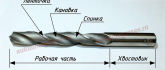
Elements of a twist drill[ | ]
A twist drill is a cylindrical rod, the working part of which is equipped with two (less often four) helical spiral grooves designed to remove chips and form cutting elements - ribbons.
- Working part The cutting part
has two main cutting edges formed by the intersection of the front helical surfaces of the grooves along which the chips flow with the rear surfaces, as well as a transverse cutting edge (jumper) formed by the intersection of the rear surfaces. - The guide part
has two auxiliary cutting edges formed by the intersection of the front surfaces with the surface
of the strip
(a narrow strip on the cylindrical surface of the drill, located along the helical groove and ensuring the direction of the drill during cutting, as well as reducing friction of the side surface against the walls of the hole).
- Shank
- for securing the drill to a machine or hand tool.
A driver
for transmitting torque to the drill or
a foot
for knocking the drill out of the conical socket.
, which ensures the exit of the wheel when grinding the working part of the drill.
Drill angles[ | ]
The apex angle is 2φ=118° and the inclination angle of the helical groove is ω=27°.
- Point angle 2φ
is the angle between the main cutting edges of the drill. As 2φ decreases, the length of the cutting edge of the drill increases, which leads to improved heat dissipation conditions and, thus, increased durability of the drill. But with a small 2φ, the strength of the drill decreases, so its value depends on the material being processed. For soft metals 2φ=80…90°. For steels and cast irons 2φ=116…118°. For very hard metals 2φ=130…140°. - The angle of inclination of the helical groove ω
is the angle between the axis of the drill and the tangent to the helical line of the ribbon. The greater the inclination of the grooves, the better the removal of chips, but the less rigidity of the drill and the strength of the cutting edges, since the volume of the groove increases along the length of the working part of the drill. The value of the inclination angle depends on the material being processed and the diameter of the drill (the smaller the diameter, the smaller ω). - The rake angle γ
is determined in a plane perpendicular to the cutting edge, and its value changes. It has the greatest value at the outer surface of the drill, the smallest at the transverse edge. - The clearance angle α
is determined in a plane parallel to the drill axis. Its values, like the front angle, change. Only it has the greatest value at the transverse edge, and the smallest at the outer surface of the drill. - The inclination angle of the transverse edge ψ
is located between the projections of the main and transverse cutting edges onto a plane perpendicular to the drill axis. For standard drills ψ=50…55°.
Variable values of the angles γ and α create unequal cutting conditions at different points of the cutting edge.
Drill angles during cutting[ | ]
Twist drill with a diameter of 80 mm with a Morse taper shank No. 6. The angles of the drill during the cutting process differ from the angles in the static state, just like those of the cutters. The cutting plane in kinematics turns out to be rotated relative to the cutting plane in statics by an angle μ, and the actual angles during the cutting process will be as follows:
Drill production
Content
- Drill manufacturing technology
- Materials for the manufacture of metal drills Coatings that improve drill performance
- Heat treatment
In this article we will tell you everything about the production of drills. You will learn:
what technology is used to make conventional twist drills;
what materials are used for production;
on what equipment the main technological operations for the production of metal drills are performed;
What are the features of heat treatment and welding?
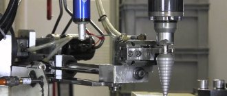
Photo No. 1: making a metal drill
Marking of cutting products
Marking drills for metal is necessary to determine the type of steel from which the cutting tool is made. The product also indicates its diameter, accuracy class and manufacturer (country). Only spiral gimlets with a diameter of less than 2 mm are not marked.
In other cases, drill markings may have the following meanings:
- P9 - made of high-speed steel with a tungsten percentage of 9%.
- P9K15 - indicates the presence of cobalt in the high-speed steel in an amount of 15%.
- Р6М5К5 - indicates the presence of a complex composition of cutting steel containing tungsten, cobalt and molybdenum.
Imported products have the HSS designation, which can be used to determine the composition of the material from which the drill was made. The HSS drill, which will be explained below, is used with an additional letter, which determines the presence of alloying metal.
- HSS-E - contains cobalt. Used in processing metals of high viscosity.
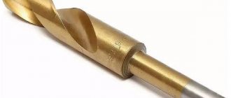
- HSS-Tin - has titanium coating, which significantly increases the hardness of the working surface, and the temperature resistance of the material increases to +600 degrees.
- HSS-E VAP is a cutting tool used for processing stainless materials.
- HSS-4241 - designed for drilling aluminum.
- HSS-R - have maximum strength.
Materials for making metal drills
In Russia, materials such as high-speed steels and hard alloys are used to make metal drills. Let's list the common brands of the first.
P9 and P18. Steel with similar characteristics. The first contains 9% tungsten, and the second - 18. Drills made from these steels drill well, do not overheat and last a long time.
Р6М5 (foreign analogue - HSS steel). Metal drills made of this high-speed steel are most often found. It contains 6% tungsten and 5% molybdenum. Tools made from this material are used to process:
Р6М5К5 (foreign analogue - HSS-Co steel). This alloy contains not only molybdenum and tungsten, but also 5% cobalt. Drills made from R6M5K5 steel are stronger than analogues made from an alloy without the addition of cobalt. These tools are used to process:
Carbide drills differ from tools made from high-speed steel by being more durable and durable. 4 types of alloys are used for production.
tungsten-free (based on TiC, TiCN with a nickel-molybdenum binder).
Coatings that improve drill performance
In the production of metal drills, two types of coatings are applied to the working parts and shanks to improve their properties.
Titanium nitride. The hardness of the surface layers of such drills increases by 2300 HV. Thermal resistance increases to 600°.
Titanium nitride alloyed with aluminum. The hardness of the surface layers of such drills increases by 3000 HV. Thermal resistance increases to 900°.
Photo No. 2: drill coated with titanium nitride
Drills with such coatings are used to process:
parts made of hard and improved alloys;
billets made of malleable and gray cast iron, in which the graphite inclusions are spherical.
If maximum reliability and wear resistance are important to you, buy these tools. You will find detailed information about choosing metal drills here.
Types of drills for metal
To choose the best models, you need to understand the types of drills.
Spiral
Classic, cylindrical drills that are most often used for drilling metals. Typically, spiral products are made of HSS steel.
The material is a high-quality cutting type of steel, so the gimlets made from it are highly durable and durable.
Conical (stepped)
The cutting surface has the shape of a cone, which is why this type of drill got its name. Conical drills are used to make holes in thin metal, as well as to correct defects from other cutting tools.
What are the best step drills to choose? Depends on the type of metal being processed. If the density of the workpiece is too high, then it is better to purchase more expensive, golden-colored products.
In everyday life, this type of drill is rarely used. If you need to frequently drill thin metal sheets or process soft materials, then despite the relatively high cost, it should be purchased for your home workshop.
Core cutters (annular cutters)
The cutting tool is a cylinder with a cutting edge, which is used to cut metal.
The energy consumption for making a hole in this way is several times lower, due to the small contact area of the tool with the surface being processed.
The advantage of using this type of drill over others is the production of large diameter holes. In this case, it is possible to obtain better quality edges than when working with spiral models.
Feathers
A special type of flat gimlet with replaceable working edges is used for drilling metal. Such products allow you to make high-quality, perfectly straight holes.
The absence of distortion during the drilling process and the ability to make a large-diameter hole in various metal structures allows many craftsmen to abandon the use of spiral products.
The low cost of feather drills allows in many cases of metal processing to call them the best for drilling holes.
These are the main types of drills used for making holes in metal structures.
Machines for the production of drills
Let's list the technological operations for manufacturing drills and name the machines, apparatus and devices that are used for processing, for example, blanks for tools with diameters from 0.1 to 1 mm, having thickened shanks.
Turning. Slitting automatic lathes 1103 are used for it.
Heat treatment. Produced in electrode salt baths.
· Vacation and rinsing. When performing drills, they are placed in special mesh baskets.
Shank grinding. A grinding machine ZM-180 or MF-63 is used.
Finishing of working parts of drills. For this operation, special finishing machines of the Steinel type are used.
Grinding of working parts. It is performed on a centerless grinding machine MF-63AP with manual feed.
Grinding of flutes. A special grinding machine MF-202 is designed for it.
Sharpening. It is carried out on a 64A machine using a binocular microscope.
To produce drills with diameters up to 12 mm, other equipment is used.
Grinding drills on cylindrical surfaces. For processing workpieces with diameters up to 2 mm, a ZM-180 or MF-63 machine is used. Larger workpieces are ground on a ZM-182 machine.
Grinding of chip flutes. Workpieces with diameters up to 2 mm are processed on an M-202P or M3460 machine. For grinding larger drills, machines 3A650, 3A682, 3A683, 3657, 3A684 and 3A684K are used.
Sharpening and pointing. These operations are performed on machines 3A681, 3A650 and 3A682.
Preservation and packaging. Special devices NO-2012, NO-2712 and NO-1894A are designed for them.
Types of drills - main parameters
Type and shape of the working part
1. A screw drill, also called a twist drill, is most often used in everyday life. With this tool, the length of which can reach 27.5 centimeters, you can drill both wood and other materials. Twist drills are produced with a diameter from 0.1 millimeter to 8 centimeters.
2. A flat drill, shaped like a feather, hence the second name - feather, used for drilling large and deep holes. Its cutting edge is made in the form of a blade. It can be made in one piece, together with the shank, or it can be attached using a boring bar or a special holder.
3. For deep drilling. If you have to drill a particularly deep hole, the depth of which exceeds 5 drill diameters, use a long drill with 2 screw channels. A special emulsion flows through these channels, cooling the tool during operation. The channels are made either inside the drill or inside tubes soldered to the back of it.
4. Single-sided cutting drill. When the hole being made must have particularly precise dimensions, take a drill designed for cutting with only one side. It has a reference plane, and both cutting edges are on the same side of the central axis of the tool.
5. The ring drill is hollow inside. Due to this design, it drills only a narrow ring in the material. These are the so-called crowns.
6. To make a center hole in the part, use a special drill called a center drill.
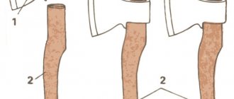
Shank design
There are several varieties of the tail section of this instrument. Let's list them. So, the shank is:
- Made in the form of a cylinder;
- made in the shape of a cone;
- faceted, having three, four or six sides;
- SDS type.
Drill making method
The drill can be made of a single piece of metal (with a diameter of no more than 8 millimeters) or an alloy (with a diameter of up to 6 millimeters). In this case, a special steel called “high-speed” is used. Her brands: P9K15, P18 or P9.
If the diameter of the drill is more than 8 millimeters, then it is made by welding. In this case, the part that cuts is made of high-speed steel, and the shank is made of carbon steel.
When it is necessary to drill weak and brittle materials, use a drill equipped with carbide plates. It has grooves that can be straight, beveled or helical.
What shape of hole needs to be machined?
Depending on the task being performed, the purpose of the drills differs. So, according to the shape of the hole, they are divided into the following types:
- Conical;
- square;
- stepped;
- cylindrical.
Features of drill manufacturing, additional methods for improving tool performance
We will talk about the features of performing the most important operations included in drill manufacturing technology, and describe the methods that are used to improve the basic characteristics of tools.
Heat treatment
It is very important. The wear resistance of the tool and the quality of the steel directly depend on the correctness of the heat treatment.
Hardening is carried out in baths with molten salts or in furnaces (electric and gas). In some cases, equipment with a vacuum or a reducing atmosphere is used to make drills.
For tempering, oils, alkalis, salts and water are used. Often the workpieces are cooled in air.
Note! Heat treatment modes are of particular importance. Therefore, all processes are controlled automatically.
Resistance butt welding
Performed on special electric welding machines. There are three technologies.
Continuous flash welding without heating. The technology is highly productive. The disadvantage is the high consumption of metal for melting and upsetting.
Heated intermittent flash welding. Takes a little longer. Metal consumption is significantly reduced.
Heated resistance welding. Almost no metal is consumed, but the operation requires highly qualified workers.
The second method is most often used.
Photo No. 3: contact butt welding
Additional methods for improving the basic characteristics of drills
Let us list the technologies that are used in the manufacture of drills to further improve their properties.
Cyanidation. The surfaces of the working parts are saturated with nitrogen and carbon. Cyanidation increases the strength of tools by 2–3 times.
Sulfidation. The surface layers of drills are saturated with sulfur. Sulfur compounds reduce friction and increase the wear resistance of tools by 1.5–2 times.
Steam treatment. After this, the instruments are placed in oil. Black oxide films form on surfaces. The strength of drills that have undergone this treatment is doubled.
Drill factories
The production of high-quality metal drills is established at a huge number of factories in Russia and abroad. Products under the following brands are popular.
Ruko. The company specializes in the production of cross-sharpened drills. Types of spraying vary. The products combine high quality and reasonable cost.
Haisser. The carbide drills from this brand are some of the best in the world. The products are expensive.
Bosh. Specializes in the production of drills with SDS shanks.
"Bison". One of the best Russian manufacturers.
SEKIRA. This is our own brand. We produce drills of various types and sizes. The characteristics of all products meet the requirements of GOSTs. You can purchase our products at the lowest price.
Study the catalog, select the drills you need and place your order. We will deliver metal-cutting tools on time.
The best manufacturers
To purchase drills and be sure that the declared characteristics are completely true, you need to choose the right manufacturer.
Companies that value their reputation do not sell products of inadequate quality. Therefore, when choosing metal drills, you should give preference to manufacturers who have been on the market for a long time.
Among the newcomers, there may also be worthy producers. But in order to find out that a good quality product is on sale, you need to make a purchase, which often represents a “lottery”.
1. Bosch - products of the German company have long proven themselves only on the positive side. Despite the rather high price of the products, when purchasing Bosch drills, you can rest assured of excellent quality. It is convenient and profitable to purchase tools from this company as a set.
Whatever set of drills you take, each one will contain only the highest quality products that will last for many years, provided they are properly stored and used.
2. “Zubr” is a domestic manufacturer whose products are maximally optimized in terms of price-quality ratio. You can purchase the products of this company either in a single copy or in the form of a set. The latter option will significantly save money, despite the significant cost of the kit.
3. Soviet-made drills - this category of cutting tools can be classified as an “endangered species.” With due diligence, you can purchase a rarity that has unsurpassed technical characteristics.
Conclusion
Which metal drills are best to buy depends on many circumstances:
- If you need to drill several holes in very thin and soft metal, then just buy a cheap drill that will do the job.
- For professional use, it is not at all profitable to purchase cheap drills. Low-quality products can lead to defects and significant time costs for frequent replacement of low-quality cutting tools.
Full catalog
Drill production technology
Drills are made using foundry
Foundry production is a set of production processes for producing critical products of complex shape and configuration at relatively low cost.
Foundry products are produced by filling special molds with molten metal, in which the metal solidifies and turns into a casting. The casting mold has a cavity inside, the outline of which corresponds to the product. In metallurgy and mechanical engineering, the share of cast parts is more than 60% of the mass of mechanisms and machines, while the share of the total costs of their production does not exceed 20 - 25% of the cost of the machines. The mass of castings varies widely: from several grams to hundreds of tons.
Currently, the foundry has mechanized semi-automatic and automatic installations and production lines that provide the ability to produce castings with increased accuracy and surface cleanliness and a small amount of machining.
About 70% of castings are made in sand-clay molds for one-time use, but in recent years semi-permanent casting molds, such as graphite-based and permanent metal molds, as well as advanced special casting methods, have become increasingly common. To obtain high-quality castings, source metals and alloys must have a number of special casting forms, the main of which are: fluidity, shrinkage, segregation, absorption and release of gases.
Fluidity is the ability of a metal in a molten state to fill molds and reproduce the contours of a casting. Liquation is the heterogeneity of the chemical composition of the material in different parts of the casting, which occurs during its solidification and leads to heterogeneity of mechanical properties in different parts of the casting. The quality of the resulting castings also largely depends on the ability of metals and alloys to absorb gases in the molten state and release gases when cooled.
The use of molding and core mixtures with increased gas permeability reduces the formation of gas holes in castings.
The process of obtaining products in a foundry consists of the following main technological stages: making models and core boxes, preparing molding and core mixtures, making cores and casting molds, preparing molten metal, pouring metal into the mold, removing the casting from the mold, trimming, cleaning and quality control castings
In the manufacture of one-time molds, sand-clay molding mixtures are used, consisting of quartz sand, refractory clay and a number of binders and auxiliary molding materials. Sand is the main molding material with high fire resistance, hardness, strength and thermochemical resistance. Clays are crushed rocks and are used as a binding material, giving mixtures plasticity and strength. The fire resistance of clay is determined by its alumina content. Binding materials are divided into organic and inorganic. Cheap petroleum products, wood, synthetic resins (bitumen, rosin, petrolatum, linseed oil, drying oil, etc.) are used as organic binding materials; as inorganic materials - an aqueous solution of liquid glass. Auxiliary molding materials improve the non-stick properties, gas permeability, fire resistance and hygroscopicity of molding and core mixtures. The most widely used are pulverized quartz, graphite, coal dust, sawdust, peat, fuel oil, etc. Core mixtures contain 95-96% quartz sand and binder. Liquid glass, linseed and cottonseed oil, molasses and other materials are used as fasteners.
Precision casting as a metal saving factor
The accuracy of processing of products obtained in one-time forms does not always meet the requirements of modern technology, as it is characterized by significant allowances for machining and large losses of metal to waste in the form of chips. Therefore, the most important direction for the further development of special casting methods. This makes it possible to increase labor productivity, geometric dimensional accuracy and surface cleanliness of castings, reduce machining allowances to a minimum, and sometimes eliminate subsequent processing of products.
The main special casting methods are: lost wax casting; casting using burnt models; casting shell molds, based on the use of special one-time molds; casting into metal molds (chills); injection molding and centrifugal casting, which use permanent molds.
Lost wax casting can be used to make drills. The dimensional accuracy of the castings corresponds to 12-14 grades, and the surface roughness is 10 grade. Therefore, products obtained by this casting method are subjected to mechanical processing only by grinding or polishing. Metal-cutting tools are mainly cast using lost wax models.
For the manufacture of lost wax models, materials are used that have a low melting point, high ductility and adhesiveness: wax, paraffin, steorin, rosin, etc.
Melting of the model composition is carried out in special baths, and pressing is done in metal molds. After hardening and cooling, the resulting models are removed from the molds, equipped with a gating system, and fire-resistant coatings are applied to the surface of the model until a hard shell is formed. Then, by heating to 120-160 0 C, the model material is melted out of the shell. The resulting hollow shell is molded in a sand-clay mixture in a flask.
Development of route technology for manufacturing drills from R6M5F3 steel
1. Receipt of workpieces - forgings (forging shop).
. Preliminary softening heat treatment - isothermal annealing (thermal section of the forge shop).
. Hardness control (thermal section of the forge shop).
. Pre-machining (machining shop)
. Final hardening heat treatment - hardening with stepwise heating, high-temperature triple tempering; improvement of the shank (thermal section of the machine shop).
. Hardness control (thermal section of the machine shop).
. Final machining (machine shop).
. Quality control of the finished part (mechanical shop).
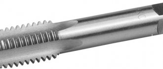
Development of route technology for manufacturing a cutting tool tap made of R6M5 steel:
1. Receipt of workpieces - forgings (forging shop).
. Preliminary softening heat treatment - isothermal annealing (thermal section of the forge shop).
. Hardness control (thermal section of the forge shop).
. Pre-machining (machining shop)
. Final hardening heat treatment - hardening with stepwise heating, high-temperature triple tempering; improvement of the shank (thermal section of the machine shop).
. Hardness control (thermal section of the machine shop).
. Final machining (machine shop).
. Quality control of the finished part (mechanical shop).
Development of a technological process for heat treatment of cutting tools:
Technological process of preliminary heat treatment
Preliminary heat treatment of cutting tools (disc cutter, drill, broach) is carried out in a chamber electric furnace type SNO8.16.5/10. The oven has ribbon heating elements arranged in zigzags in two rows along the side walls, on the oven floor and on the roof. Bottom heating elements are placed on special alundum combs and protected by massive metal heat-resistant tiles with side ribs or carborundum film. The ends of the heaters are brought out to the rear wall and protected by a casing. The furnace damper has a tube with a number of holes for supplying protective gas.
) reduce carbide heterogeneity of cast and rolled steel;
) reduce hardness and thus ensure the possibility of cutting;
) prepare the structure for hardening and prevent naphthalene fracture.
For isothermal annealing, the steel is heated to a temperature 20-30 ° C above A3 and, after holding, quickly cooled to a temperature slightly below the critical point A1 - 700 ° C. At this temperature, the steel is maintained until the austenite completely disintegrates and is then cooled in air.
The advantage of isothermal annealing compared to conventional annealing is a significant reduction in annealing time and obtaining a more uniform structure. The isothermal holding temperature affects the resulting structure and properties. With a decrease in the isothermal holding temperature, i.e. With an increase in the degree of overcooling of austenite, the cementite grains are crushed and fine-grained pearlite is obtained.
Annealing is carried out in an electric furnace type SNO 8.16.5/10, which, in terms of its productivity, ensures the implementation of the production program and the required temperature range of the heat treatment mode.
) Preliminary heat treatment and assignment of technological parameters for a disk cutter.
first heating of the tool in an electric gas furnace type SNO8.16.5/10 to a temperature of 650°C. Heating duration is 20-25 minutes. Holding at heating temperature for 20-30 minutes.
second heating of the tool to a temperature of 920°C. Heating duration is 20-25 minutes. Holding at heating temperature for 1 hour.
cooling in oven to 500°C
air cooling to site temperature
hardness control of 10% of workpieces from a batch using the Brinell method
control of heat treatment mode.
A characteristic feature of annealing tungsten-free high-speed steel is the formation of a ferrite-cementite mixture from austenite at a constant temperature. When 11M5F steel is heated above the critical point, a transition of pearlite to austenite occurs. The mechanism of the process of transformation of pearlite into austenite consists in the nucleation of austenite grains and their growth. When heated slightly above the critical point A1, the initial austenite nuclei are formed by shear (α → γ) while maintaining coherence. As the nucleus grows, the coherence of the α and γ lattices is disrupted, the shear mechanism is replaced by a normal growth mechanism, and the austenite grains acquire an equiaxial shape. Isothermal exposure is necessary for complete decomposition of austenite and the formation of pearlite.
) Preliminary heat treatment and assignment of technological parameters for the drill.
heating is carried out in an electric chamber furnace type SNO8.16.5/10 to a temperature of 840-860°C. Heating duration »5 min. Holding at heating temperature for 10 minutes.
cooling in the oven to 720-730°C and holding for 2 hours
cooling in the oven to 600°C
air cooling to site temperature
hardness testing using the Brinell method
control of heat treatment mode.
heating in an electric chamber furnace type SNO8.16.5/10 to a temperature of 840°C±10°C. Holding at heating temperature for 20 minutes.
air cooling to site temperature
hardness testing using the Brinell method
control of heat treatment mode.
) Preliminary heat treatment and assignment of technological parameters for the tap
heating is carried out in an electric chamber furnace type SNO8.16.5/10 to a temperature of 840-860°C. Heating duration »5 min. Holding at heating temperature for 10 minutes.
cooling in the oven to 720-730°C and holding for 2 hours
cooling in the oven to 600°C
air cooling to site temperature
hardness testing using the Brinell method
control of heat treatment mode.
heating in an electric chamber furnace type SNO8.16.5/10 to a temperature of 840°C±10°C. Holding at heating temperature for 20 minutes.
air cooling to site temperature
hardness testing using the Brinell method
control of heat treatment mode.
General conditions for choosing a drainage system: The drainage system is selected depending on the nature of the protected area.
Organization of surface water flow: The largest amount of moisture on the globe evaporates from the surface of the seas and oceans (88‰).
Mechanical retention of earth masses: Mechanical retention of earth masses on a slope is provided by buttress structures of various designs.
Countersinking holes
Countersinking is the process of processing holes produced by casting, stamping or machining in order to increase accuracy and reduce roughness.
Countersinking occurs when using a working tool - a countersink.
This tool has three to six blades. Like a drill, the working part of a countersink includes cutting and calibrating parts. The cutting depth is calculated in the same way as when drilling (half the difference in the diameters of the countersink and the hole being machined).
The countersink has the same angles as the drill, with the exception of the angle of inclination of the transverse edge: the countersink does not have it, the angle of inclination of the grooves is ≈10 o -20 o.
A countersink is stronger than a drill. When processing holes of 13-11 quality, countersinking can be the final operation.
Countersinking is used to process cylindrical or conical recesses (for screw heads, sockets, valves, etc.), mating cylindrical and conical, end and other surfaces, through and blind holes.
This method is considered productive - it increases the accuracy of pre-machined holes and partially corrects the curvature of the axis after drilling. To increase the processing accuracy, devices with jig bushings are used.
In practice, in addition to countersinking, counterboring is used. The working tool is a counterbore. Countering is used when it is necessary to obtain grooves, for example for seals, end planes, which are supporting surfaces for bolts, screws or nuts.