A huge number of different jobs that are constantly performed using lathes has led to the creation of a number of cutters that allow productive technological operations to be performed. They all have a different design and purpose for which they were created.
Each turning cutter , depending on what geometric shape it has, received its own separate name. It depends not only on the form, but also on its properties and purpose. All of them will be listed below.
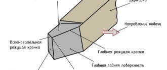
1 – straight cutter through passage; 2 – bent through; 3 – pass-through persistent; 4 – scoring cutter; 5 – wide passage; 6 – boring cutter; 7 – boring thrust; 8 – cutting cutter; 9 – thread cutter; 10 – shaped cutter.
Pass-through straight cutters are used if you need to grind the outer surface of a cylindrical shape.
Thrust cutters are used for turning cylindrical surfaces and shafts with small shoulders. If you pay attention to the shape of the cutter, then the main angle of such a tool is exactly ninety degrees. This will reduce the vibration that appears during work.
A straight-through bent cutter is considered a more universal tool. Without changing its position in the tool holder, you can grind both cylindrical surfaces and trim the ends of the workpiece. This cutter is often used to process stepped shafts or any other parts that, as a result of the technological process, require trimming a small shoulder.
A scoring cutter is used to machine external end surfaces. During operation, the feed of the tool must be such that its movement is perpendicular to the axis of rotation of the part that will be processed.
Boring cutters are used to bore various through holes that have been previously machined with a drill.
Boring thrust cutters are also used for boring parts after drilling. Typically this tool is used for machining blind holes.
Parting cutters are used to cut material. Usually, in order to get the desired result when performing work with such cutters, you need to choose a tool whose head length will be greater than the radius of the workpiece itself. In this case, the rule is observed when the thickness of the head towards the body of the cutter gradually decreases. This is done to minimize the friction that is generated during cutting of the part between the end planes and the auxiliary cutting edges.
Thread cutters are used to cut internal or external threads. In this case, the profile of the thread that is being cut must correspond to the shape of the cutting part of the tool.
Grooving cutters are used for processing technological grooves of various profiles and purposes.
Shaped cutters are used to process special shaped surfaces. In this case, it is important to maintain the profile that will be at the cutting edge of the tool. It must be such that it corresponds to the profile of the workpiece and its surface that will be processed. Such cutters are sharpened exclusively on the front surface. For this reason, the edge profile does not change.
Modern, efficient production is characterized by the use of special cutters, which are equipped with non-sharpening and often multifaceted carbide inserts. When the blade wears out, the plate is removed and rearranged in such a way as to secure the next unused edge of the blade.
Shaped cutters
- Home /
- Mechanical restoration /
- Shaped cutters
Shaped cutters are non-standard cutters.
Shaped cutters are used for processing parts with a complex generatrix shape. Compared to conventional cutters, they provide identical shape, dimensional accuracy of the part, which depends mainly on the manufacturing accuracy of the cutter, high productivity due to the simultaneous processing of all sections of the shaped profile of the part, and greater savings in machine time. Cutters are designed to process a specific part, and their use is economically justified in large-scale and mass production.
Rice. 1. Shapes of shaped cutters.
| A) | b) |
| V) |
Shaped cutters are classified according to the following criteria:
1. In shape - rod (Fig. 1, a), prismatic (Fig. 1, b) and round (Fig. 1, c).
- Rod cutters are used for processing short shaped surfaces. Their disadvantage is the small number of regrinds due to the low height of the working part.
- Prismatic shaped cutters have a greater number of grinds and can process longer shaped surfaces. Fastening and basing of the cutter in a special tool holder is carried out using a dovetail fastening. The disadvantage of prismatic cutters is the inability to process internal shaped surfaces.
- Round shaped cutters are used for processing both external and internal shaped surfaces. They are more technologically advanced than prismatic ones and allow a greater number of regrindings. The cutters are installed in a special tool holder and aligned along the hole and end.
2. In the direction of supply: radial (Fig. 2, a) and tangential (Fig. 2, b).
Rice. 2. Radial and tangential shaped cutters. Sr - radial feed of the cutter, St - tangential feed.
3. According to the location of the axis of the hole or the mounting base of the cutter in relation to the axis of rotation of the workpiece: with a parallel or inclined arrangement.
4. By design: solid and composite, for example, with soldered carbide plates.
Table 1
Geometric elements of the blade of the working part of shaped cutters
| Workpiece material | Front angle g, deg. | |
| BRS | TS | |
| Aluminum, copper | 20 — 25 | 10 — 15 |
| Bronze, lead brass | 0 — 10 | 0 — 5 |
| Steel with sv, MPa: | — | — |
| up to 500 | 25 | 20 |
| 500 — 800 | 20 — 25 | 15 — 20 |
| 800 — 1000 | 10 — 15 | 5 — 10 |
| Cast iron with NV: | — | — |
| up to 200 | 12 — 15 | 8 — 10 |
| over 200 | 8 | 8 |
| Rear angle, a | 8 — 15 | 8 — 12 |
| Note: BRS - high-speed steel, TS - carbide | ||
table 2
Dimensions of shaped disk cutters with holes for pins, mm.
| Workpiece profile depth, tmax, mm, no more | D | D (H8) | d1 | bmax | K | r | D1 | d2 |
| 6 | 50 | 13 | 20 | 9 | 3 | 1 | 28 | 5 |
| 8 | 60 | 16 | 25 | 11 | 3 | 2 | 34 | 5 |
| 11 | 75 | 22 | 34 | 15 | 4 | 2 | 42 | 5 |
| 14 | 90 | 22 | 34 | 18 | 4 | 2 | 45 | 6 |
| 18 | 100 | 27 | 40 | 23 | 5 | 2 | 52 | 8 |
| 25 | 125 | 27 | 40 | 30 | 5 | 3 | 55 | 8 |
Table 3
Dimensions of shaped disk cutters with end grooves, mm.
| Workpiece profile depth, tmax, mm, no more | D | D (H8) | d1 | bmax | K | r | D1 | d2 |
| 4 | 30 | 10 | 16 | 7 | 3 | 1 | — | — |
| 6 | 40 | 13 | 20 | 10 | 3 | 1 | 20 | 3 |
| 8 | 50 | 16 | 25 | 12 | 4 | 2 | 26 | 3 |
| 10 | 60 | 16 | 25 | 14 | 4 | 2 | 32 | 3 |
| 12 | 70 | 22 | 34 | 17 | 5 | 2 | 35 | 4 |
| 15 | 80 | 22 | 34 | 20 | 5 | 2 | 40 | 4 |
| 18 | 90 | 22 | 34 | 23 | 5 | 2 | 45 | 5 |
| 21 | 100 | 27 | 40 | 25 | 5 | 2 | 50 | 5 |
Notes:
- For a given profile depth tmax, it is allowed to use cutters with large overall dimensions, for example, for a workpiece with a profile depth of 7 mm, cutters with overall dimensions for tmax< 14 mm can be used.
- The rake angle g is selected according to the table. 1
- The size of Lp depends on the length of the surface being processed.
- Dimensions
| Rice. 3. Tool holder for round shaped cutter | Rice. 4. Tool holder for prismatic shaped cutter |
- Turning cutters
- Axial tool
Digital library
General technical disciplines / Cutting tools / 2.7.1. Types of shaped cutters
Shaped cutters are designed for processing external, internal and end surfaces of complex profiles. They are widely used both in large-scale and mass production, and in small-scale and individual tool production (as a second-order tool). The achievable dimensional accuracy of parts corresponds to 7-8th quality with high productivity. The shaped turning process is performed with low cutting speeds and low (up to 0.05 mm/rev) feeds due to the relatively long length of the cutter blade (up to 80 mm).
Shaped cutters as a type of turning cutters can be classified according to various criteria:
— in shape – flat, prismatic and round;
- by type of feed - axial, radial and tangential;
- according to the location of the axis (or mounting base) in relation to the axis of the part - with a parallel and inclined arrangement of the axis;
- according to the shape of the front surface - with a positive front angle; with a positive rake angle and cutting edge angle;
- according to the shape of the forming shaped surfaces - with ring generatrices and with helical generatrices;
- by design - solid and composite.
In terms of feed type, there is no fundamental difference between shaped and conventional turning and automatic turret cutters. However, the shape of shaped incisors has specific features.
Flat shaped cutters
(Fig. 2.24) are no different in design from conventional turning rod cutters and are used in individual and small-scale production. Typically, to maintain the profile of the workpiece, flat shaped
the cutters have and are ground along planes parallel to the supporting surface of the cutter (planes 1-1, 2-2, 3-3 in Fig. 2.24).
The main disadvantage of flat shaped cutters is that due to the presence of a lateral clearance angle (Fig. 2.41a) on blades located perpendicular or oblique to the axis of the part and limited on both sides by ledges, the profile of the tool is not preserved during regrinding , and therefore the details (see Fig. 2.24a).
Sometimes, to maintain the profile of the part, a chamfer of mm is made on the rear end surfaces of the cutter. For part profile depths of more than 3 mm, an auxiliary plan angle is made at the end sections of the profile of flat shaped cutters (Fig. 2.24b). Rear angles for flat incisors are selected within .
Rice. 2.24. Flat shaped cutter
Prismatic profile cutter
It is a prism, one of the side faces of which has a shaped surface and serves as the back surface of the cutter, and the side opposite to it has a dovetail for mounting in the holder.
The front surface of the prismatic cutter is one of the end planes.
The clearance angle of a prismatic shaped cutter is formed when it is installed in a holder, and the front surface is sharpened at an angle.
Rice. 2.25. Prismatic shaped cutters: a – radial; b – tangential
Depending on the installation relative to the part and the feed direction, prismatic cutters can be radial or tangential (Fig. 2.25). Prismatic shaped cutters have found limited use due to the complexity of their manufacture.
Round shaped cutter
There is a body of rotation with a corner groove cut into it to create a rake face and space to accommodate chips. To obtain rear angles, the center of the cutter is raised by an amount relative to the center of the part (Fig. 2.26). If =0, i.e. the centers of the cutter and the part would lie on the same axis, then since the tangents to the rear surface and the cutting plane coincide (see Fig. 2.26, b) Obviously (see Fig. 2.26, a). From this relationship it follows that the clearance angle along the length of the blade of a shaped cutter is not the same and increases towards the center of the cutter.
Rice. 2.26. Diagram of a round shaped cutter
Typically, the clearance angle along the length of the blade of round incisors varies within . The rake angle for both round and prismatic shaped cutters is selected depending on the material of the part: for steel; cast iron; bronze, brass.
The overall dimensions of a round shaped cutter can be approximately found according to the dependence (see Fig. 2.26a):
, (2.11)
where is the depth of the part profile; mm – depth of sharpening of the front surface required to accommodate chips; mm – cutter wall thickness; =10...25mm – radius of the mounting hole.
Round shaped cutters are widely used on lathes and turret machines due to the comparative simplicity of their manufacture, as well as the large, almost unlimited number of regrinds. These cutters are universal in application
tion, since they can process all types of shaped surfaces - external, internal and end.
The process of sharpening cutters for metal
To sharpen cutters, sharpening and grinding machines with a constant cooling function are used. The main surface of the product is first sharpened, then the back and additional surfaces. At the final stage, the original configuration of the front face is returned.
Photo No. 11: the process of sharpening the cutter
For the operation, two grinding wheels are used: silicon carbide and electrocorundum. Silicon carbide is suitable for machining high-speed steel products. Electrocorundum is made from carbide materials. To check the degree of sharpening, special templates are used.
Types of cutters for lathe
Image No. 2: types of metal turning tools (diagram)
Types of cutters for a lathe are prescribed in GOST. According to the document, products belong to one of the following categories:
- solidly brazed from alloy/tool steel;
- with soldered plate;
- with removable plate.
According to the direction of the working movement, turning tools are classified as left-handed or right-handed.
Carbide inserts for cutting edges are made from steel grades VK8, T5K10, T15K6, T30K4, etc.
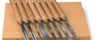
Types of shaped cutters
Shaped turning cutters are used for turning parts of complex shapes, as well as cutting chamfers. Often such products are made to order (for specific parts), which is justified only for mass production. There are several typical types of instruments.
Photo No. 1: the process of processing a shaped workpiece with a cutter
- Rod - suitable for processing short surfaces. They have a small working part height.
- Prismatic - designed for working with complex surfaces. Mounted on dovetail type holders.
- Round - adapted for processing external and internal parts of parts. Special holders are provided for mounting.
Types of through cutters
Pass-through type cutters are used for processing the ends of workpieces and chamfering. Products come in two main varieties: straight and curved. Bent-type through-thrust products are also distinguished. They are used for working with cylindrical workpieces. In one cycle, the tool removes a significant amount of excess metal from the material.
Photo No. 2: the process of processing a shaped workpiece with a cutter
Photo No. 3: bent cutter
Photo No. 4: bent thrust cutter
Types of cutting tools
Cut-off cutters are the most widely used. The products are used for cutting workpieces at an angle of 90 degrees and making grooves of different depths. This type of tool can be visually distinguished by its thin base with a carbide plate soldered onto it. The main types of cutting cutters: right- and left-handed.
Photo No. 5: cutting tools
Types of thread cutting tools
The products are designed for cutting external and internal threads. The first ones have a spear-shaped cutting plate. The latter are similar in appearance to a boring tool and are equipped with square-section holders. The products are suitable for carving only large holes.
Photo No. 6: internal thread cutters
Photo No. 7: external thread cutters
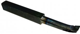
Types of boring cutters
To process blind and through holes, you need to buy cutters for metal, choosing boring-type models.
Products for making blind holes are equipped with a triangular cutting plate. The working part has a bend.
Photo No. 8: Boring cutters for blind holes
The through hole tool is suitable for boring previously drilled recesses. In this case, the depth of the hole is determined by the length of the holder. The layer of metal being removed is approximately equal to the bend of the working part of the cutter.
Photo No. 9: Boring cutters for through holes
Prefabricated metal cutters
The classification of types of turning tools will be incomplete without mentioning the prefabricated tool. Such products are considered universal, since they can be equipped with cutting inserts for various purposes. Typically, such products are installed on computer-controlled machines and are intended for contour turning, making blind and through holes and other specialized metal work.
Photo No. 10: prefabricated metal cutters
Tool Requirements
A lathe can use a variety of cutting tools, each of which will operate under more severe conditions than any machine part. For this reason, increased demands are placed on the material from which they are made.
The hardness of the tool should always be higher than that of the workpiece being processed. If this is not observed, then instead of cutting there will be a crushing of the cutting edge.
High wear resistance is the most important requirement for metal-cutting tools, on which the processing time before subsequent regrinding depends.
High heat resistance implies the quality of a tool in which it is capable of processing without loss of cutting properties despite the high temperature.
High mechanical strength affects the tool’s resistance to cutting forces, which reach high values during processing. The material from which the cutting tool is made must work well in both bending and compression.
Read also: Rules for working with a hand jigsaw
Shaped cutters are used to process parts with a shaped profile. Compared to conventional cutters, they provide:
- identity of shape, dimensional accuracy of parts, since they do not depend on the qualifications of the worker, but mainly on the accuracy of the manufacture of the cutter;
- high productivity due to large savings in machine time associated with a reduction in the cutting path, and auxiliary time required for installation and adjustment of the cutter when changing it;
- high durability due to the large number of permissible regrinds;
- fewer defects;
- ease of sharpening.
In Fig. 76 shows a processing diagram using ten simple and two shaped cutters. In the first case, the processing time
Figure 76 – Scheme of operation of shaped cutters
equals 41/2 min. (incisors B, C, F, G, K, J were taken into account), while in the second it is about 11/2 minutes, i.e. the savings are 3 times. Installing two shaped cutters is much easier and faster than installing ten cutters. Sharpening two cutters requires many times less time than sharpening ten cutters.
Due to their high cost, shaped cutters are used in large-scale and mass production.
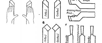
Types of shaped cutters
In practice, there are a variety of shaped cutters, which are divided into the following types (Fig. 77):
- according to the shape of the cutter: round (Fig. 77, a) and prismatic (Fig. 77, b);
- by installation relative to the part: radial (Fig. 77, a, b) and tangential (Fig. 77, c);
- according to the location of the axis of the hole or the mounting base of the cutter in relation to the axis of the part: with a parallel arrangement of the axis of the hole (Fig. 77, d) or the mounting base and with an inclined arrangement of the axis of the hole (Fig. 77, e) or the mounting base;
- according to the location of the front surface: with a positive (or equal to zero) rake angle (Fig. 77, a, b) or with a positive rake angle and the angle of inclination of the cutting edge (Fig. 77, e)
- according to the shape of the forming shaped surfaces: with ring generatrices (Fig. 77, a, f) or with screw generatrices (Fig. 77, g).
Figure 77 – Types of shaped cutters
A round cutter is mounted on a mandrel and is protected from turning by means of teeth or corrugations made on one of its ends (Fig. 78). The prismatic cutter is secured in the holder using a dovetail and screws.
Figure 78 – Fastening shaped cutters
Radial forming cutter
Radial cutters have a round or prismatic shape, tangential cutters most often have a prismatic shape. Round cutters are used for external and internal processing, while prismatic ones are used only for external processing.
The radial cutter is installed in relation to the workpiece in such a way as to ensure transverse feed along the radius. During the cutting process, the axis of the part is intersected by one or more points on the cutting edge of the cutter. Due to the wide range of work, the radial cutter operates in difficult conditions, as a result of which it is necessary to use reduced cutting conditions. When processing a long workpiece with a small cross-section, there is a danger of it bending from the cutting force.
Tangential profile cutter
The tangential cutter is installed tangent to the inner circumference of the product profile. The cutting edge is equipped with a bevel at an angle φ (see Fig. 77, c). This allows him to work not with the entire profile at once, but with sequential input into work of all points of the cutting edge. Profile processing ends when the last point of the edge passes through the axis of the workpiece.
Tangential cutters are recommended for processing workpieces that are not very resistant to deflection and shallow profiles.
In practice, cutters with a parallel arrangement of the hole axis (for round ones) or the mounting base (for prismatic ones) relative to the axis of the workpiece have become widespread. An inclined arrangement of the hole axis or fastening base is used in exceptional cases when the configuration of the part in individual sections of the profile does not provide optimal rear angles with a parallel arrangement.
Read also: Classification and design features of milling machines
To improve the cutting process, shaped cutters must be equipped with a positive rake angle (see Fig. 77, a, b). Cutters with a positive angle y and an inclination angle of the cutting edge λ (see Fig. 77, e) are used with increased requirements regarding compliance with the shape of the part and the accuracy of its specified dimensions (for example, in a critical section 1-2 of length l).
Round shaped cutters
Round cutters are usually made with ring-shaped shaped surfaces.
Compared to round cutters, prismatic cutters have reliable fastening, a wide choice of clearance angles, greater cutting edge strength, better heat dissipation, and also provide greater precision in machining the part.
However, in practice, round cutters have become more widespread, which is mainly explained by the ease of their manufacture as bodies of rotation.
Cutting tool is a tool designed to change the shape and size of a workpiece by removing part of the material in the form of chips or sludge in order to obtain a finished part or semi-finished product. Subdivided:
- · by type of application - manual and machine (machine), construction, installation, etc.
- · by type of material being processed - metal-cutting, wood-cutting, etc.,
- · according to the type of material used - high-speed cutting, for high-speed processing, etc.,
- · by type of workpiece - gear-cutting, thread-forming, etc.,
- · by the nature of the processing - abrasive, grinding, etc.,
according to the cleanliness of the processed surface - roughing, semi-roughing, finishing, semi-finishing, super-finishing.
Types of planing cutters
Planing products differ from turning products by having a backward curved head and a top that does not coincide with the reference plane of the tool. This design is explained by the technological features of metal processing. If the cutter were not curved, it would break under the pressure of the removed layer of metal.
Image No. 3: types of planing cutters (diagram)
According to the type of work performed, tools are divided:
- on passages for horizontal planes;
- cutting for ledges;
- for cutting workpieces;
- shaped for working with complex surfaces.
Types of cutter wear
The cutting tool wears out during use.
- Wear on the rake edge occurs due to friction of the chips on the tool surface. As a result, a depression is formed on the edge, located behind the build-up of the stagnation zone (1–2 mm from the edge).
- Flank wear occurs due to its friction against the machined surface. As a result, a wear area appears on the edge.
Typically, the front edge wears during roughing, and the back edge wears during finishing.
There are several stages of tool wear:
- running-in;
- steady wear;
- critical wear.
We recommend not bringing the cutter to the last stage, as this leads to its destruction and shortening its service life. Sharpening will allow the tool to return to its original geometry.