- Straight through turning tools and their purpose
Design features of turning tools
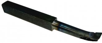
Each turning tool consists of two parts.
- Holder. Can be square or rectangular. With its help, the cutter is secured in the mounting sockets of the machines. GOST establishes the following standard dimensions of holders.
Square - 4*4, 6*6, 8*8, 10*10, 12*12, 16*16, 20*20, 25*25, 32*32, 40*40 mm.
- Rectangular - 16*10, 20*12, 25*16, 25*20, 50*25, 40*32, 50*32, 50*40, 63*50 mm.
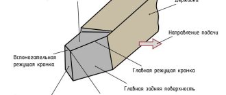
Image #1: Lathe cutter design
Fangs
The fangs have a cone-shaped elongated shape and are used for tearing, holding food, for defense (in animals), and also for releasing poison (in snakes). In humans, fangs are less affected by caries, because they do not have irregularities on their surface in which pathogenic bacteria would accumulate. Also, the dentin in canines is thicker than in other teeth.
Some animals have overdeveloped fangs - tusks. For example, elephants and walruses. They help the latter to climb out of the water onto the ice or to search for food at the bottom. They help elephants in defense or competition with other males for a female.
Geometry of turning tools
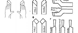
Image No. 2: turning tool geometry
Let's talk about the angles of the incisors and their purposes.
- Back auxiliary angle (α1). As it decreases, the friction force between the rear plane of the tool and the workpiece decreases.
- Apex angle (ε). Formed between the cutting edge and the rear auxiliary plane. The larger this angle, the better the heat removal conditions and the higher the strength of the cutter.
- Auxiliary plan angle (ϕ1). Its size varies from 10 to 30°. As the angle decreases, the cleanliness of the treatment improves, but the friction force increases.
- Leading angle (ϕ). Its size varies from 20 to 90°. The length and width of the cut depend on the size of the angle. The smaller ϕ, the lower the temperature and cutting force. The cleanliness of the processing is also improved. But as the angle decreases, vibration and radial cutting force increase.
- Cutting angle (δ). Formed between the rake surface and the cutting plane.
- Basic rake angle (γ). Its size varies from -5 to +15°. As the angle increases, it is easier for the tool to cut into the metal, chip removal is improved, and the cutting force, deformation of the machined surface, and power consumption are reduced. However, this reduces heat dissipation and reduces the service life of the cutting edge.
- Taper angle (β). Formed between the front and main back surfaces. Affects the sharpness and strength of the tool.
- Main relief angle (α). Its size varies from 6 to 12°. As the angle decreases, the friction force between the part and the back surface of the cutter decreases. This improves heat dissipation and extends the service life of the tool, but the cleanliness of the machined surface deteriorates.
- Angle of inclination of the main cutting edge (λ). Affects the direction of chip removal. At positive λ and λ = 0°, the chips move towards the machined surface. Cutters with positive λ (12–15°) are used when processing workpieces made of heat-resistant and hardened steels. For universal turning tools, λ = 0°. Cutters with negative λ are used for finishing.
Metal turning cutters
METAL TURNING CUTS
The need to perform various types of metal processing work on lathes led the engineering industry to the creation of several types of metal turning tools.
WATCH THE VIDEO ON TURNING CUTS:
And the main types of turning tools are:
Passing (roughing) Finishing Trimming Cutting Boring
There are also others, but these are special purpose cutters:
Threaded Shaped Slotted, etc.
. Purpose of cutters for lathes:
Passing cutters are designed for roughing parts, that is, for removing the greatest thickness of the surface layer of a product, for which special precision is not required. And to perform these functions, the cutter has a special shape of the cutting part, which allows for minimal load on the cutter, which in turn allows the machines to have high productivity.
Finishing cutters are designed to perform particularly precise work, where a prerequisite is to achieve specified dimensions with tolerances measured in microns and, accordingly, the cutting part of the turning cutter has a unique shape that allows achieving the required results.
Scoring cutters are used for processing end surfaces; their shape allows this function to be performed most productively.
To obtain specified lengths, so-called cutting tools are used. Their cutting part has a very thin shape, which leads to frequent breakage. Performing this operation requires a lot of skill and experience from the turner.
To carry out internal processing of parts: boring diameters, recesses, boring cutters . And depending on the depth of the operation being performed, the size and length of the boring cutter are selected.
.
The cutters are also divided according to the direction of movement of the cutting process: right and left.
How to determine the direction: place the hand on top of the cutter, on which the bent thumb will indicate the direction of the cutting movement of the cutter. To which hand this movement coincides is called a cutter.
. Cutting materials.
Depending on the purpose of the work being performed, cutters have a cutting part made of different materials. For example, to perform rough metal processing, the cutting part must be resistant to impacts and be harder than the surface being processed.
And for finishing, the cutting part must be resistant to high temperatures, that is, the hardness of the cutting edge should not decrease due to friction and increased temperature in the cutting zone.
The so-called metal-ceramic hard alloys (tungsten, titanium and tantalum cemented with cobalt) have such properties.
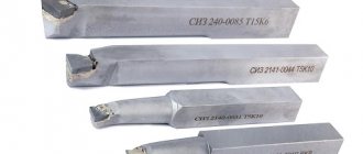
For example, cermet alloys are used for roughing: VK2, VK4, VK6, VK8 are alloys with a high tungsten content.
And for finishing operations they use such alloys as: T5K10, T5 K12., T14 K8, T15K6, T30K4 - where the letter T and the adjacent number indicate the percentage of titanium carbide contained in the alloy, and the letter K - cobalt.
Also, for the production of cutters, high-speed steel grades P18 and P9 are used.
. Incisor sizes.
Tool holders of this type can be made in various sizes (in mm):
8x8; 10x10; 12x12; 16x10 (for training machines); 20x12 (this size is considered non-standard); 25x16 (the most common size); 32x20; 40x25 (products with a holder of this size are made mainly to order; they are almost impossible to find on the open market).
All requirements for metal cutters for this purpose are specified in GOST 18877-73.
.
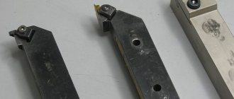
Cutters with mechanical fastening of replaceable inserts.
Despite the high quality of modern methods for soldering carbide plates, the production of such cutters is sometimes accompanied by the formation of cracks and subsequent destruction of the plate. Therefore, recently they have been trying to replace soldering or welding of plates (especially mineral-ceramic ones) with mechanical fastening.
In this case, the plate is fixed in the cutter shaft by means of a clamp and a bolt. One end of the clamp rests on the plate, and the other on the corrugated surface (the pitch of the corrugations is 1.5 mm). When the plate is worn by 1.5 mm, the clamp can be moved forward (for this purpose, the hole for the bolt securing the clamp is made oblong). In the working position, the right edge of the plate rests against the shoulder pad located on the lower side of the clamp.
. Holder for mechanical fastening of carbide inserts.
When replacing a dull blade with a new one, there is no need to remove the cutter from the machine. The disadvantage of this method of securing the plates is that they are only about half used. In addition, the bolt, clamps and other parts that secure the plate wear out quickly.
In recent years, in relation to mechanical fastening, multifaceted, non-sharpening plates have begun to be produced. In cases where the length of the cutting edge of a cutter, for example a boring cutter, may be short, it is made short and of small cross-section. To secure such cutters, holders of various designs are used. Holders are also used to secure shaped and threaded cutters.
.
Cutters through passage (roughing)
It should be remembered that when rough turning parts, chips of large sections are removed, as a result of which significant cutting forces arise, under the influence of which the part can be torn out of the chuck. Therefore, the fastening of the part in the case under consideration must be especially strong.
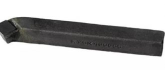
Rough turning cutters usually work with large chip cross-sections and often at high cutting speeds. Therefore, such a cutter must be durable, well absorb the heat generated during the cutting process, and not lose hardness from heating during operation. The shape of the cutter should be such that chip separation occurs as easily as possible.
Carbide cutters for rough turning are called through cutters. The advantage of straight through cutters, which differ from each other only in the shape of the carbide plate, is that the processing of their rods is carried out by milling or planing, without forging. Bent cutters are made by forging. Nevertheless, they are widely used, since they can produce not only longitudinal, but also transverse turning.
. Finishing cutters are persistent.
Such cutters should provide surfaces with the least roughness. Their shape is chosen in accordance with this requirement.
The figure shows a finishing cutter used for finishing turning with low feed; such cutters work in both directions, i.e., both right and left, they are called blade or wide.
While working with the finishing cutters mentioned above, sometimes hard inclusions that are in the material of the workpiece are pulled out. As a result, depressions appear on the surface of the part, spoiling the surface. Therefore, if it is necessary to obtain a very clean surface of a part, it is processed with a spring cutter.
The cutting edge of the spring cutter does not tear out inclusions in the material of the part, but as it moves away from the surface being processed, it smoothes them out. However, when the cutter is springing, the shape and dimensions of the part are often inaccurate even on a good, working machine. When working with a spring cutter, you can get good results if you remove several chips one after another.
If the requirements for surface cleanliness are low (within class 5-6), finishing of external cylindrical surfaces is often carried out using conventional cutters, guided by recommendations for the selection of angles and other elements, as well as standard rules for installing cutters.
Pass-through cutters are straight and bent; in addition, they are sometimes more convenient when processing surfaces that are difficult to reach with a straight cutter. Passing thrust cutters are especially suitable for processing parts with small ledges formed by the same cutter. The main angle of these cutters is 90°, which helps reduce vibrations during operation. Therefore, thrust cutters are successfully used when processing non-rigid parts.
. Parting cutters
Cut-off cutter equipped with a carbide plate. The cutting edge of such a cutter is usually made perpendicular to the axis of the cutter head. In this case, however, the part being cut breaks off before the cutter reaches the center and it remains with a “tail”, which after cutting has to be filed off with a file or cut off with a chisel.
In order for this tail to be obtained from that part of the material that is clamped in the chuck, the cutting edge of the cutter is beveled by 5°. With this shape of the cutter, the tail remains with the part of the material fixed in the chuck and can be removed by further feeding the cutter forward.
To improve the cleanliness of the surface obtained after cutting, chamfers 1-2 mm wide are made on the rear auxiliary surfaces of the cutter.
The material of cutting tools is high-speed steel and hard alloys.
Cutting cutters should be installed exactly on the center line. It is known that when installing a cutter below the center line, its rake angle decreases, the chip pressure on the cutter increases and the fragile cutting cutter breaks.
By installing the cutter above the center line, we reduce its clearance angle, as a result of which the friction of the rear surface against the machined surface of the part increases. This, in turn, often causes breakage of a fragile cutting tool.
The larger the diameter of the part being cut, the longer the length of the cutting tool head should be. The required strength of a cutter with a long head is only possible with a sufficient width of the cutter.
. Scoring cutters.
A scoring cutter is only suitable for processing open surfaces, such as the end of a part secured in a chuck without support from the rear center. It is not suitable for machining the ends of shafts and other parts supported by the rear center.
Before the top of such a cutter approaches the center of the surface being processed, the right end of its main cutting edge will rest against the center. The use of a half-center does not help in this case.
The advantage of the cutter in question is the massiveness of its head, which absorbs cutting heat well.
When processing parts fixed without support by the rear center, their end surfaces facing the tailstock can be turned with passing and finishing cutters, installing them in the tool holder parallel to the line of the centers of the machine.
Scoring cutters are available right and left. Right-handed cutters are used for processing end surfaces. The ledges facing the tailstock are processed with right-handed cutting tools, and those facing the headstock with left-handed scoring incisors.
. Boring cutters.
Boring cutters are designed for processing through and blind holes.
The shape of the front surface and all the angles of these cutters, with the exception of the back one, are taken to be the same as those of the through cutters used for external turning.
The dimensions of the boring cutter also depend on the corresponding dimensions of the hole.
Allowances for rough boring are determined by the nature of the workpiece and in many cases are removed by several passes of the cutter. Feeds during rough boring are selected depending not only on the depth of cut, but also on the overhang of the cutter and the diameter of its rod.
When rough boring a hole, the cutter must be installed slightly below the center line of the machine.
However, it is impossible to install the cutter significantly below the center line, since this would require an increase in the rear angle of the cutter. This causes a decrease in the sharpening angle of the cutter and, consequently, a decrease in its strength, as well as the ability to remove heat.
If the boring cutter is installed above the center line during fine boring, then its top will move down under the pressure of the chips being removed. The diameter of the bored hole will be smaller than expected, which can be corrected by the next cutter pass.
When fine boring holes, the cutter must be installed slightly above the machine center line.
. Former.
Cutters whose cutting edge coincides with the profile of the surface being processed are called shaped.
Shaped cutters: ordinary (a), prismatic (b) and disk (c)
The advantage of the incisors under consideration is their simplicity, and therefore the relatively low cost of their production.
A significant drawback of such cutters is that after several (and sometimes after one) regrinding, their profile changes and the cutter becomes unsuitable for further work.
Therefore, rod shaped cutters are used primarily in cases where the work is not of a massive nature and sharpening of the cutters is rarely done.
A prismatic shaped cutter is shown in Fig. b. The front surface is the end of the block from which the cutter is made, and the rear angle is formed due to the inclined position of the cutter in the holder.
When sharpening a cutter along the front surface, its profile does not change. The disadvantage of the cutter is the difficulty of manufacturing.
A disk shaped cutter mounted on a holder is shown in Fig. V. The front surface of the disk cutter is located below its axis by an amount h, which creates the required clearance angle. Under this condition, the manufacture of the cutter is simplified; In addition, the cutter is not pulled into the part and the processed surface of the latter is of high quality.
The width of shaped cutters usually does not exceed 40 mm, but sometimes shaped cutters up to 100 mm wide are used.
The correctness of the shaped surface is checked with a template. There should be no gap between the treated surface and the template.
If the workpiece surface has large differences in the diameters of different sections, then when working with a shaped cutter you have to remove a lot of metal.
. Threaded cutters.
Cutters for cutting external and internal triangular threads must have a cutter profile angle of 60° for metric threads and 55° for inch threads.
The top of the cutter is made with a flat cut or rounded in accordance with the shape of the cavity of the thread being cut. Since the cut size or radius of curvature of the cavity is selected depending on the thread pitch, each such cutter is suitable for cutting threads of only a certain pitch.
The profile angle of the thread cutter is very important, since if it is reduced or increased, the thread being cut will end up with an incorrect profile. The profile of the cutter when sharpening it is checked with a thread template.
Thread cutters are made with plates made of high-speed steel or hard alloys. When cutting threads on steel parts, carbide cutters with plates made from alloys of grades T15K6 and T14K8 are used for preliminary cutting and T30K4 (or T15K6) for final cutting, and on cast iron - grades VK6M, VKZM, VK2 or VK4.
The surface roughness of a thread cut by a cutter largely depends on how carefully and sharply the cutter is sharpened. The cutting edges of the cutter must be without jaggedness, which is achieved by finishing the cutter.
Marking of turning tools, meaning of numbers and symbols
According to the standard, the marking of turning tools may include 9 or 10 characters.
- The first is the method of attaching the cutting insert.
- The second is its shape.
- The third is the type of cutter.
- The fourth is the rear corner of the cutting insert.
- Fifth - cutting direction.
Image No. 6: possible values of parameters 1–5
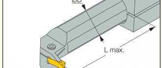
- The sixth is the height of the holder.
- The seventh is the width of its tail section.
- The eighth is the total length of the incisor.
- The ninth is the size of the cutting plate.
Image No. 7: possible values of parameters 6–9
- The tenth is indicated if necessary. Indicates the accuracy of some cutter parameters.
Image No. 8: possible values for parameter 10
Chewing teeth
Chewing teeth are divided into molars and premolars. The latter are located after the fangs in front of the actual molars (molars). Small molars contribute to tearing and grinding food, and molars perform a direct chewing function. They have several roots and canals, which allows them to be attached to the jaw more strongly than other teeth, but due to the many grooves, tubercles and depressions on the surface, the risk of developing caries in them is higher.
Operating rules
Turning cutters are capable of performing their main function for a long time until the working surface is ground down. But improper use will shorten the life of the tool. To prevent preliminary wear, you need to follow simple operating rules:
- Install centrally.
- The larger the dimensions of the workpiece, the larger the cutter should be.
- Turn on cooling when operating in heavy conditions.
- Sharpen in a timely manner.
- Periodically polish the working surfaces with a fine-grained stone without removing the tool from the tool holder.
- Apply the tool to the workpiece manually, and after touching, turn on the automatic feed.
- When stopping the machine, first manually retract the tool, then turn off the unit.
- Select the correct cutting modes.
- Do not store the tool in a pile - this will lead to chips and cracks on the cutting edge.
- When working with a cutting tool, bring it as close to the chuck as possible.
Many types of work are performed on a lathe. A separate cutter is provided for each process. It is selected based on the material being processed, cutting conditions, cleanliness and roughness parameters. The tool must be sharpened in a timely manner, and the rules of operation and storage must be followed.
Names of teeth and their main functions
Every person knows why teeth are needed. These bodies are entrusted with a number of functions:
- Food. With their help, a person grabs and chews food.
- Speech. In combination with the tongue, these organs make speech intelligible.
- Aesthetic. A beautiful snow-white smile is a surefire way to endear yourself to any person.
If all teeth have the last two functions simultaneously, a real division of labor operates when organizing the digestion process in the jaw. The canines, incisors and molars work like a real team, which is why it is so important that they are all healthy. Let's take a closer look at their functions: