Types and purpose
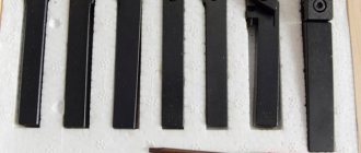
Using pass-through cutters, they roughly peel off workpieces made of steel, alloys and non-ferrous metals, and also perform fine turning. Their types are described below.
Straight
Used for cutting conical and cylindrical parts. The heads are straight. If turning goes from left to right, use a passing left cutter. When the caliper moves from right to left, the right incisor is placed. Well suited for rough peeling because they have great rigidity.
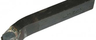
Bent back
The working part is curved to the left or right. For processing conical, cylindrical, end surfaces and chamfering. You can work close to the chuck jaws. Universal than other types and more often used.
Persistent
Thrust tools allow cutting workpieces in steps. Can shoot up to 5 mm. metal thickness per pass.
Often performed with bends in the working part to the right or left.
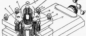
Prefabricated
The working part of the cutter 1, into which the pin 3 is seated, a carbide plate 2 is put on it. It is secured with a wedge 5 and a screw 4. This way it is securely clamped in the cutter body.
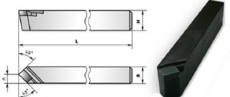
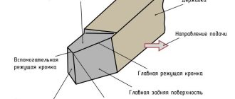
Geometry of a bent cutter
Consumer properties are determined by the following geometric parameters:
- size and direction of the front surface (ensures continuous removal of generated chips during operation);
- rear main surface parameters;
- rear auxiliary surface.
The cutting edge is formed by the line of intersection of two surfaces. On one side, the front surface approaches it; on the opposite side, the main rear surface approaches it. In the design of a bent cutter, one more cutting edge is distinguished. It is formed by the junction of the front surface and the auxiliary surface. That is why it is called the auxiliary cutting edge. The point where both edges meet is called the tip of the cutter. This part of the cutter takes on the heaviest loads during the processing of the workpiece. To prevent premature failure, it is given a rounded shape. Therefore, an individual rounding radius is specified for a specific type. An additional way to increase the strength of the tip and make it more reliable is to form a transition cutting edge. It is given a rectangular shape.
For turning bent cutters, their geometric parameters are of great importance. The most important of these are the angles at which the tool surfaces are positioned.
For a more complete understanding of the available parameters, each bent turning cutter has a drawing. It displays the main parameters:
- general view of the product;
- angle values;
- marking;
- appointment;
- permissible processing conditions (type of machine, processing speed, characteristics of the material being processed).
The drawing shows the following angles:
- at the apex of the bent cutter (it is formed by projections onto the main plane by the main and cutting edges);
- inclination of the line of the main cutting edge;
- additional angles that define the geometry of all surfaces.
The angle values and edge parameters determine the basic properties of the cutting tool. For each model (depending on the tasks being solved), its own geometric shape is created. For example, to process parts that have a stepped design, the cutting edge is sharpened at a right angle.
Main dimensions and features of cutter geometry
| Height, mm | Width, mm | Length, mm |
| 16 | 10 | 110 |
| 20 | 12 | 120 |
| 25 | 16 | 140 |
| 25 | 20 | 170 |
| 32 | 25 | 170 |
| 40 | 25 | 200 |
| 40 | 32 | 240 |
| 40 | 40 | 240 |
| 50 | 40 | 240 |
| 50 | 50 | 240 |
The front surface is beveled to remove cutting products. The main cutting edge cuts metal. The apex is the intersection of the cutting edges. The angles of a turning cutter, or rather the sharpening of its tip, are determined by the type of work.
Groove cutter
Types of groove cutters
Turning cutters for grooves come in two types, for external and internal surfaces. Accordingly, each type of work requires a tool change. Therefore, when working with several parts, first they process one surface on all of them, and then work on the other. The groove cutter for internal grooves, as well as the internal groove cutter, have a design in which the inserts can be changed.
In external machining, the use of carbide tools on inserts turns out to be practically useless, since they do not give the necessary results, and their cost is too high. When it comes to internal processing, then the issue of rigidity and the minimum diameter of the workpiece comes to the fore, since otherwise the groove cutter may simply not fit into the hole. Therefore, the internal grooving cutter must be stiffer and thinner to be versatile in use.
photo: types of groove cutters
Main dimensions and materials
Turning cutters for internal grooves are available with carbide inserts:
| Height, mm | Width, mm | Working length, mm | Working part width range, mm |
| 10 | 10 | 100 | 2,5-3,5 |
| 16 | 16 | 170 | 3,5-4,5 |
| 20 | 20 | 200 | 3-6 |
| 25 | 20 | 140 | 3,5-6,5 |
| 25 | 25 | 240 | 5-6,5 |
| 32 | 32 | 200 | 5-10 |
photo: dimensions of groove cutter for external grooves
The groove cutter for external grooves is produced with brazed carbide inserts:
| Height, mm | Width, mm | Working length, mm | Working part width range, mm |
| 16 | 10 | 100 | 2-10 |
| 20 | 12 | 120 | |
| 25 | 16 | 140 | |
| 25 | 20 | 140 | |
| 32 | 20 | 270 | |
| 50 | 32 | 200 |
Groove cutter geometry
When selecting a cutter for a groove, a very important parameter is the rake angle, which has a strong influence on the vibration resistance of the tool. The smaller the angle, the less stability. The best option here is a value in the range from 15 to 25 degrees. The clearance angle should be between 8 and 12 degrees.
The cutting edge must be uniform, otherwise uneven grooves will be obtained. Taking into account the fact that a groove cutter is most often made of carbide materials, it is quite difficult to sharpen and here the chips are not divided into two parts, but go only in one direction. The product, unlike some other types, has only one sharpening angle.
photo: geometry of a groove cutter
Selection of Grooving Cutter
In order for a groove cutter to serve for a long time and be effective in use, its choice should be taken quite responsibly. First of all, you should pay attention to the microgeometry of the plate. Tight tolerances when machining parts can be around 0.025mm. There are several variations in the shape of the cutting insert, as a result of which the shape of the future groove depends, since it may not always be flat. Some universal type inserts have a curved cutting edge, so that the bottom is convex.
The geometry of the edge must be selected very accurately, since if the load is unevenly distributed, then wear will occur differently in all parts of the product and, as a result, it will no longer be usable. The same situation occurs when the blade begins to chip, after which it must be replaced immediately.
Cutting mode
The cutting width per pass must correspond to the required depth. The groove cutter is fed manually. This should be done within minimal limits, approximately 0.1 mm per revolution. The cutting speed is set noticeably lower, about 20% less than when working with other cutters.
There are several types of grooves, which are made using different techniques:
- Small cylindrical ones are made in one pass of the machine. The cutter is placed at a given distance, then brought into contact with the surface. Then, in one motion, a pass is made, as a result of which the product is processed.
- Grooves on the ledges and ends are made using a similar technique. Only here the depth is maintained according to the longitudinal movement dial, and the diameter is maintained according to the transverse feed dial.
- Large grooves are difficult to machine in one pass, so they are done in two steps. The first step is to draw a rectangular shape to the entire required depth. After this, the cutter is changed and the metal remaining from the sides is removed with a profile cutter.
- Rectangular wide grooves are also made in several passes. Here, both on the first pass and on all subsequent ones, you need to slowly cut through the metal not to its full depth. When the desired depth is reached, the bottom must be cleaned.
Marking of incisors
Using the T5K10 cutter as an example, we can consider the principle of marking these products. The letter “T” means that it belongs to the hard alloys of the titanium-tungsten group and there is 5% titanium carbide (the number “5” in the marking), and 10% cobalt (“K”) (the last number).
Manufacturers
- Zenitech (Switzerland);
- Proma (Czech Republic);
- Itertool (China)
Labeling and manufacturers
The marking is applied on the side. It indicates the brand of carbide or quick cutter. Inscription: T15K6. Letter T - titanium carbide. The number 15 is the percentage of titanium carbide, K6 is six percent cobalt.
For quick cutters, after P is the percentage of tungsten. F - vanadium, M - molybdenum.
Manufacturers:
- Sverdlovsk Tool Plant (SIZ).
- Izhevsk Instrument Plant (IZ).
- Khrapunovsky Tool Plant (KHIZ).
- LLC "Melitopol Instrument"
- ZIGUN - Hard Alloy LLC.
- ARNO FREDERICHS AFC - Germany.
Parting and Grooving Tool Models in SolidWorks
As mentioned in earlier articles, 3D models of a cutting tool can, of course, be built from scratch in SolidWorks. But I think there is no point in this since the tool manufacturers have already done this for us.
We go to the website, and for example, download two models of cutters under the designations: “RAG123H10-32B” , “RF123H13-2525BM” .
Sandvik coromant website
And in the search line, enter these designations one by one and download the cutters by clicking on “Download” in the “download detailed 3D model” line.
Downloading a 3D model of the tool from the Sandvik coromant website
Next, open the downloaded files and get 3D models of these cutters in SolidWorks.
Internal grooving cutter RAG123H10-32B
Parting and grooving cutter RF123H13-2525BM
As you can see, this is much easier and faster than creating a cutter in SolidWorks from scratch.
If anyone needs this model, you can download it at the end of the article!
Criterias of choice
The type of cutter and brand indicate the processing of the part in the technical process.
State standards for tools
- Thrust-through high-speed cutters - GOST 18870-73.
- — — — — — — — — — — — carbide — GOST 18879-73.
- Bent-through high-speed cutters - GOST 18868-73.
- - - - - - - - - - - - - carbide - GOST 18877-73.
- Straight through high-speed cutting GOST - 18869-73.
- — — — — — — — — — — — carbide — GOST 18878-73.
- Prefabricated cutters GOST - 26611-85.
Selecting a beveled cutter
The choice of the necessary tool depends on the following requirements that are presented in the manufacture of a particular part. These requirements include:
- type of processing (finishing, semi-roughing, roughing, high-precision processing);
- tool feed directions (right or left);
- the nature of cutting or removing a layer (passing, thrust, scoring, threading);
- holder length;
- type of tip (solid, welded, removable);
- shape of the cutting element (triangular, rectangular, special design).
Depending on the complexity of the problem being solved, a bent cutter is selected that is capable of high-quality processing on a specific type of machine. The most universal is considered to be a bent through cutter with replaceable plates. The exact purpose of a particular instrument is determined by the accepted standard and indicated on the marking. The bent cutter T15k6 is used for surface treatment of parts made from various grades of steel, including alloyed ones. Alloy VK8 is used for roughing work, drilling, processing of internal surfaces, and milling. The variety of types of structures requires their evaluation according to the criterion of efficiency - cost. It is this that affects the final price of the manufactured part.