A cutting cutter is a type of turning tool designed for through cutting of a workpiece with a narrow and deep groove. Such cutters are most often used to separate the machined part from the bar fed through a hole in the spindle. In their design, they differ from through, boring, threaded and other metal turning tools, which is due to the specific operation of their cutting edge. The cutting operation takes up a small part of the total processing time of the part, but, as a rule, it is the last in the work cycle, and therefore the quality of the end of the part depends on it. Incorrect choice of sharpening angles for the cutting plate increases the risk of unevenness and chipping on the cut surface, which can lead to defective parts or the impossibility of further processing. One of the main features of a cutting turning tool is that its head part during processing is immersed in a narrow groove, the transverse dimension of which is slightly larger than the width of the cutting edge blade. This creates certain difficulties for chip removal and tool cooling and therefore requires special design solutions.
Cut-off lathe device
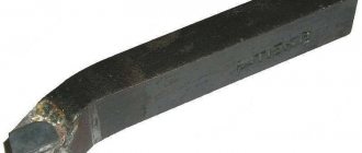
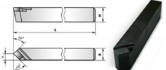
Structurally, an all-metal cutting turning tool consists of a massive holder and a flat head ending with a cutting plate (see the left drawing in the figure below). Unlike other types of cutting tools, here, in addition to the main cutting edge, there are also two auxiliary ones, which are located on both sides of it and are intended for trimming the side surfaces of the groove being cut. In a cutting cutter, the blade tapers towards the holder at angles from 1º to 3º on each side. This is done in order to reduce friction between the cutter and the groove walls, as well as improve chip control and coolant circulation.
The width of the head blade can be from 3 to 10 mm, and its length must be selected several millimeters greater than the radius of the workpiece. To increase strength and reduce vibration, special models of cutting tools with an enlarged front part are used.
Balance is given to such a tool by heads that have a rounded protrusion at the top (“cockerel”), which allows the cutting edge to be positioned in line with the axis of the holder (see the lower right drawing in the figure above).
Methods for joining carbide inserts to steel
More than 60% of all plates are installed into the tool by soldering. This is due, first of all, to the simplicity of the fastening technology.
The quality of soldering is influenced by many factors, among which are the type of flux and solder, as well as the material of the holder. In addition, the adhesion force of the plate to the tool body depends on the surface frequency, heating temperature and type of cooling. Due to the different values of the thermal coefficient of linear expansion of the plate and holder, due to differences in materials, residual stresses are formed during soldering. During further operation of the cutter, they can cause cracks to appear on the surface of the plates. Carbide plates are soldered using copper-based solders. Silver solders are used only in the production of particularly complex tools.
When soldering, fluxes are used to wet the surfaces of the materials being sintered. This is done to prevent oxidation processes from occurring, which contributes to a more rigid adhesion of the plate to the holder.
Various types of structural and alloy steels are used as material for the tool body. The most common steel grades are 30KhGSA, 45.
In cases where there is a strong cyclic load, fastening by soldering is replaced by fastening by diffusion welding in a vacuum. Welding occurs as a result of the penetration of atoms of contacting surfaces into each other. This process takes place under conditions of elevated temperature and pressure. This technology allows you to increase the adhesion force of the plate to the holder by 2-3 times.
The development of new types of adhesives has also made it possible to use the gluing method when fastening carbide plates. The main advantage of this method is the absence of the formation of internal stresses, which has a positive effect on the durability of the cutter. The strength characteristics of the adhesive are increased by doping its composition with various fillers, in particular asbestos.
The glue connection performed well when working with low heat generation and cutting force. This is finishing and semi-finishing of cast iron and non-ferrous alloys.
More and more production is beginning to produce removable carbide inserts, which are attached to the tool using threads and have the ability to rotate around an axis. Previously, they are given a special shape in the form of polyhedra (triangle, rhombus, rectangle), each side of which is a cutting edge. All this allows you to reduce the time or completely avoid re-sharpening.
This method is becoming more and more popular from year to year, because... as it has a number of significant advantages:
- No thermal stress.
- Easy to replace dull blades.
- High level of productivity.
Types and purpose of cutting tools
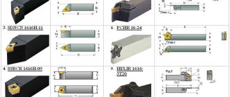
According to their design, cutting tools are divided into all-metal and prefabricated. The first ones are made of tool steel, and their standard sizes and designation rules are regulated by GOST 18874-73. The maximum GOST dimensions of such a cutter are: total length - 80 mm, head length - 15 mm, blade width - 12 mm. With this tool, as the cutting edge is sharpened, the length of the head decreases and, consequently, the maximum cutting diameter decreases.
Prefabricated cutting tools can be divided into two main types. The first includes a cutting tool in which the holder and head are made of one piece of metal, and the cutting plate is a separate assembly element mounted at the end of the head. There are two main types of fastening, according to which cutters with mechanical and soldered fastening of plates are distinguished. The second type is a prefabricated cutting tool that has recently become widespread, in which a flat and long head with a cutting part is mechanically attached to a special mandrel that acts as a holder (see figure below). These cutters come with replaceable inserts of varying widths and thicknesses. In addition, some of them have adjustable head extension length.
In addition to normal and reinforced cutting tools of traditional design, there are a number of varieties for working in special conditions, including those that compensate for the shortcomings of low-power and non-rigid turning equipment. These include spring and inverted cutters, which are mainly used in home workshops and small industries. Spring cutters have an arched head and are designed for processing materials with an uneven and hard surface on small machines with a flexible structure. This head compensates for dynamic shocks and smoothes out vibration, which allows you to achieve the desired surface quality and protect the cutting insert from damage.
Inverted cutters became popular five or six years ago when a very easy to use and efficient cutting insert was developed.
Features and advantages of inverted cutting tools
This type of cutting tool got its name due to the fact that it operates on a reverse (counterclockwise) spindle rotation. The design itself resembles a stationery knife: a holder and a long blade in the form of a plate with a bevel at the end. The blade is made of high-speed steel alloyed with cobalt and in cross-section looks like an inverted letter “T” with short crossbars (see picture below). The sharpening angle of the end of the cutting edge is 7º, the size range of thicknesses produced by the manufacturer is from 1 to 3.2 mm.
The main advantage of this cutter is the facilitated removal of chips, since when the spindle rotates in reverse, it immediately goes down under its own weight. With this mode, the likelihood of clogging the groove with chips is sharply reduced, which is often the cause of jamming and tool breakage. Other advantages of this model include:
- ease of sharpening the blade;
- work at long reach;
- improved cooling mode (chips from below, coolant from above);
- long service life even with repeated sharpening of the plate.
In addition, its arbor has a precise height adjustment system, which eliminates the need to adjust the position of the tool using shims.
Types of carbide inserts - explanation of markings, designations, classification
Content:
- Grades of carbide inserts for turning
- An example of deciphering the markings of a turning plate
- Marking of threaded plates
- An example of deciphering the markings of a threaded plate
- Marking of carbide cutting and groove inserts
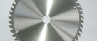
- Marking of milling inserts
- An example of decoding the markings of a milling plate
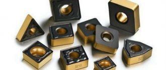
There is a huge variety of carbide inserts for turning and milling machines on the market today. Understanding the markings of plates, their types, shapes and sizes, even for a non-novice in turning, is not an easy task. In this article we will try to sort out all the carbide inserts, especially those presented in our online store.
Carbide inserts for specific tools
This characteristic is one of the simplest - the plates are placed on turning tools, drills or milling cutters, which means that this is the purpose we choose.
Turning plates are also easy to understand.
By purpose they are:
- Turning inserts
- Parting and grooving
- Threading Inserts
Turning inserts are selected for specific holders (cutters). You need to know such characteristics as the size and shape of the carbide insert, the grade of the insert, its radius, mode and type of turning (from roughing to finishing). Also, before purchasing replacement inserts, you need to decide what materials this alloy is suitable for processing. There are more universal alloys, and there are narrowly targeted plates.
How to understand the markings of carbide inserts
Grades of carbide inserts for turning
There are many standards and manufacturers, on average the plate markings are more or less the same (for example, according to ISO), there are slight variations among some brands. You need to “read” the insert from left to right; the name of the interchangeable tool says a lot - shape, angles, tolerances, length of the cutting edge, shape of the chipbreaker, etc.
The tables below provide explanations for the designation of turning plates .
As for chipbreakers, the Chinese company GESAC is constantly improving them. In 2022, new products appeared - LM and LR chipbreakers. You can read more about the new products in our Blog here.
Designations of the main GESAC chip breakers:
The letters and numbers after the chipbreaker designation indicate the type of alloy from which the tool is made. Here, each manufacturer has its own traditional designations.
An example of deciphering the markings of a turning plate
For clarity, let's decipher the turning insert CNMG090304-QF GP1115 from GESAC.
Let's look at the first four letters - CNMG . C – rhombus, N – clearance angle 0°, M – height tolerance limit +/- 0.08-+/- 0.18 mm; thickness +/- 0.13; the size of the inscribed circle is d +/- 0.05-+/- 0.13 and G indicates that the plate has a hole.
Let's go further - the numbers 090304 in the name of the plate “say” that the length of the cutting edge is 9.52 mm (09), the thickness of the plate is 3.18 mm (03) and the corner radius is 0.4 mm (04). The chipbreaker is at the insert in the example QF, which means that it is intended for finishing of steel and steel-based alloys. The most recent designation in the marking is alloy GP1115.
You can always seek advice from CNCMagazine managers to select the right tools for turning and milling machines. Write to us by E-mail: [email protected] cncmagazine. ru . Phone 8 (800) 555 4116.
Marking of threaded plates
The designation of replacement inserts for thread cutting is easy to understand. The major manufacturers of carbide inserts have more or less the same markings.
Below is a table to decipher the name of the threaded plate :
Threaded inserts are available for cutting internal and external threads, usually in right-handed or left-handed versions. An important characteristic of the tool is the thread profile. The CNCMagazine online store offers a tool with the following profile :
- ISO metric thread full profile
- Thread partial profile 60° and 55°
- Whitworth Pipe Thread
- British BSPT pipe thread for steam, gas and water pipes
- American Tapered Pipe Thread (NPT)
- American ABUT profile
- Trapezoidal thread 30°
- API thread (round)
- American UN thread, full profile
Each profile has its own standards, recommendations, and technical characteristics.
Let us take an example of the markings of a carbide insert for thread cutting.
An example of deciphering the markings of a threaded plate
Let's take a 16ER0.75ISO DM215 plate. 16 is the plate size (9.525 mm). ER in the marking indicates that the insert is intended for cutting external threads, right-handed. The following number - 0.75 means that the thread pitch is 0.75 mm. ISO - indicates that the thread standard is metric according to ISO. The last thing in the name is the alloy from which the tool is made.
Carbide insert codes often overlap between different manufacturers. Most often, only the names of the alloys used differ.
Marking of carbide cutting and groove inserts
brands of tools for cutting and grooving , as well as manufacturers. Different brands have their own markings. To quickly and easily decipher the purpose of the tool and find out its characteristics, look at the tables below.
Let's try to decipher the plate ZTFD0303-MG YBG202 . ZT means the tool is designed for grooving and turning, F means the insert is 3.0 wide, and D means it's a double-sided insert. 03 – cutting edge width is 3 mm, and apex radius is 0.3. M is the accuracy grade and G means the insert has a conventional chipbreaker. YBG202 is an alloy.
A breakdown of triangular-shaped cutting plates for processing straight and radius grooves from one Chinese brand is presented below.
Marking of milling inserts
Replaceable inserts for cutters come in trigonal (W), square (S), round (R), octagonal (O), rhombic 86° (M), rectangular 85° (A), pentagonal (P) and other shapes (Z). The shape of the cutter plate can be recognized by the first letter in the name. The second letter is the clearance angle of the insert, followed by the accuracy class, then the insert type. The first number after the letters in the name of the insert is the length of the cutting edge in mm.
Then comes the thickness of the plate, also in mm. You can tell the nose radius by the name of the milling insert.
As an example, let's look at the markings of milling inserts from the manufacturer SANDVIK.
An example of decoding the markings of a milling plate
APKT11T308-APM YB9320 cutters using this diagram
Insert shape – rectangular, relief angle 11°, accuracy class K, insert size 11, radius 0.8, alloy YB9320.
On our website, each product is described in detail, its characteristics, recommended types of processing, materials, etc. are indicated.
If you find it difficult to choose the right tool for metal turning and milling, we are always happy to help you.
We are waiting for your questions and requests for metalworking tools: by E-mail, by phone 8 or fill out the application below.
Online store
SEND YOUR APPLICATION
Markings used
There are three GOSTs that establish rules for marking cutting tools. The standard sizes and coding of tools made of high-speed steel are regulated by GOST 18874-73, with carbide plates - GOST 18884-73, curved (“cockerel”) with carbide plates - GOST 18894-73. It is impossible to determine the type and geometry from markings without using GOST tables. In all three standards, each type has its own code and group of parameters, listed in tables. The only informative element of the marking is the designation of the carbide of the cutting insert. For example, a right-hand quick cutter with a cross-section of 16×16 mm, a length of 80 mm, a head of 15 m and a blade width of 12 mm is designated as 2120-0519 GOST 18874-73. The remaining two GOSTs adhere to the same marking system. A cutting cutter with a similar geometry with a carbide plate is designated 2130-0255 T5K10 GOST 18884-73, where T5K10 is a hard alloy with titanium carbide and cobalt (the numbers are percentages). Some manufacturers, in accordance with international standards, mark the type of insert material with color (applied to the end of the holder). For example, T5K10 is indicated in yellow.
In addition to GOST, there is a universal international system for designating cutting tools ISO. This is a lengthy document with many tables containing the characteristics of indexable inserts, so it is only appropriate to give here an example of the marking of a parting cutter with indexable inserts, which belongs to the group “External parting and grooving”: QFGD2525R2252H. Decoding of code positions:
- Q – cutting holder.
- F – end processing.
- G – plate size.
- D – for double-sided plates.
- 25 – holder height.
- 25 – holder width.
- R – right, neutral, left.
- 22 – maximum processing depth.
- 52 – minimum cutting diameter.
- H – position of the insert when machining face grooves.
The ISO standard partially or completely repeats the marking systems of leading manufacturers of cutting tools, as well as the new Russian GOST ISO 5609-2015.
How are the plates marked and who produces them?
By marking carbide structures for turning tools, you can determine the composition of the production material. In particular, the T15K6 marking means that the product is made on the basis of an alloy of the titanium-tungsten-cobalt group. Tungsten is mandatory in these alloys. In addition to tungsten, the alloy must additionally contain:
- tantalum;
- cobalt;
- titanium and others.
The composition of such an alloy, in accordance with the marking, contains titanium carbide in the amount of 15 percent and cobalt in the amount of 6 percent, respectively.
The most well-known manufacturers of these products used for mechanical fastening on cutters are:
- Ceratizit (Luxembourg);
- BDS-Machinen and Proxxon (Germany);
- Instrument-Service and Novomoskovsk Pipe Plant (Ukraine).
Advantages of carbide inserts for cutters
The main advantages of carbide inserts for cutting tools over high-speed cutting tools are the ability to work with high cutting speeds (up to 500 m/s for steel) and maintaining hardness at high (up to 900 °C) temperatures in the processing zone. There are two main methods for securing carbide inserts to the head of a holder: soldering (as well as similar methods) and mechanical fastening. Permanent connections are structurally simpler and more resistant to vibration when operating under heavy loads. But, despite the more complex manufacturing technology, a cutting tool with plate fastening mechanically has a number of undeniable advantages:
- no thermal effect on the holder head during fastening of the cutting part;
- the ability to quickly replace the plate or rotate with another cutting edge;
- use of different types of plates on one type of holder;
- preservation of the geometric characteristics of the cutter after replacing the insert.
In addition to cutting elements made of hard alloys, ceramic plates are used when processing particularly hard materials. They are more fragile, but are characterized by increased wear resistance of the cutting edge and can operate at very high temperatures in the cutting zone (up to 1200 °C).
Advantages of using turning inserts
Inserts for cutting or boring cutters are produced on the basis of different grades of carbide alloys. This is very convenient, since it will allow you to equip yourself with a large set of cutting elements that will process workpieces made from different elements.
And the use of replaceable turning devices for a cutting tool can confidently be called a profitable solution from an economic point of view, since if a breakdown or wear occurs, there will be no need to change the entire cutter, only its cutting part. It is best to use a tool equipped with replaceable carbide inserts when it is necessary to automate technological processes. This is especially important for small and medium-scale production of various products.
Carbide products that are placed on turning tools have a number of advantages:
- they are cheaper compared to solid incisors;
- you can replace the carbide cutting element with a new one very quickly;
- plates based on hard alloys are highly reliable even under intensive use;
- if necessary, such replaceable cutting parts can be readjusted;
- All existing models of these cutting elements for cutters are unified, so you can easily select the appropriate option for a particular type of processing, as well as the grade of material of the workpiece being processed.
And the use of replaceable carbide inserts equipped with mechanical fastening can significantly increase the service life of the turning tool holder, and there is also no need to sharpen and solder the cutting part. In addition, under the conditions of use of this tool, the temperature and cutting force can be reduced by up to 40 percent. Carbide alloys have such properties that they can be used for the production of plates, and they can be used to process metals, subject to changing cutting conditions.
Currently, different types of carbide products are produced. The requirements for each type are specified in state standards. They are presented below:
- GOST 19086–80 - implies the characteristics of support and cutting plates, as well as chipbreakers;
- GOST 19042–80 - prescribes the requirements for the shape, classification, as well as the designation system for replaceable inserts based on carbide materials;
- GOST 25395–90 regulates the production of several types of carbide inserts; they are fixed to the cutter holder by soldering. This applies to elements connected by soldering to turret, pass-through or boring cutters.
Recommendations for choosing cutting tools for metal
A cutting lathe is a highly specialized tool and is used to perform only two types of operations: cutting and turning narrow grooves. Therefore, for home and small repair shops, one of the main criteria when choosing it will most likely be price. In the case of a one-time use of this tool, a Russian cut-off cutter with brazing is quite suitable, the price of which is one and a half to two times less than that of one carbide insert with mechanical fastening. In mass production, especially on CNC machines and automatic lathes, either the cutting operation is the final one, or it is followed by the transfer of the part to the sub-spindle for further processing. Under these conditions, special requirements are placed on the geometry and quality of work of the cutting tool, so in such industries there is simply no alternative to high-tech cutters with replaceable inserts.
Product classification parameters
Replaceable carbide inserts mounted on a turning tool are classified according to certain parameters:
- type of tool - turning cutters are grooving, shaped, cutting, scoring, boring and others. Each of the listed types will require a different profile shape, which is formed at the production stage of the cutter plate;
- production material - the properties of carbide materials change depending on the amount of titanium, tungsten and other materials present in them. Replaceable inserts can also be made on the basis of ceramics; in this case, they are used mainly for the purpose of processing heat-resistant alloys, and they are also relevant in cases where continuous finishing or semi-finishing of metal workpieces is required;
- size - depending on the size of the workpiece being processed using a lathe, you need to select a carbide plate with the required geometric parameters. For a turning cutter, regardless of its type, products with appropriate parameters are selected;
- the size of the relief angle - this parameter is determined by the brand of the product; it determines how cleanly the metal workpiece will be processed. And the larger the clearance angle, the cleaner the surface treatment will be. Inserts with large clearance angles are mainly used for turning soft metals;
- accuracy class - currently manufacturers produce plates of 5 such classes. With their help, you can process products with different tolerances depending on the geometric parameters of the workpiece.
How to install a parting cutter
In order to perform cutting correctly without increased wear of the cutting plate, as well as to ensure the required quality of the end after cutting, it is necessary to align the cutter strictly perpendicular to the part. In addition, it must be installed opposite the axis of rotation with a vertical deviation of no more than ± 0.1 mm. Placing the edge of the blade even a few tenths of a millimeter higher can cause the cutting blade to break, and placing it too low can leave an uncut step on the workpiece. Cutting must be done as close to the chuck jaws as possible, using a cutter with a minimum overhang.
To facilitate the processing of complex materials on desktop machines, spring and inverted cutters are used. But, probably, craftsmen use other designs for these purposes, as well as various improvements to “standard” cutters. If you know anything about this, please share information in the comments to this article.