Manual and mechanized riveting techniques
TO
category:
Riveting
Manual and mechanized riveting techniques
Next: Riveting defects, measures to eliminate them and safety rules
Depending on the conditions for the formation of the closing head, two riveting methods are distinguished: direct and reverse. With a free approach to the rivet from both sides, a direct (or open) riveting method is used, in which blows are applied from the side of the rod; The mounting head rests against the support (Fig. 1,a). If there are conditions that make it difficult to insert rivets from the support side, the reverse (or closed) riveting method is used. The rivets are inserted from the worker's side, and the blows are applied to the setting head, while the rod rests against the support; the closing head in this case is formed with the help of support (Fig. 145.6). An example would be riveting in pipes, riveting flanges in hard-to-reach places, etc.
Rice. 1. Sequence of riveting: a - direct method; b—reverse method
Manual riveting is usually done at a mechanic's workplace and is done in a vice or on a workbench. In some cases, connections with countersunk rivets are made on the slab.
To obtain high-quality rivet joints, the mutual fit of the parts is of great importance. The parts to be connected must be tightly fitted to one another and fit into place without tension. Poor fit of parts leads to stress after riveting, to the formation of cracks, bulges, etc. Drilling holes for rivets is carried out according to punched markings. To ensure that the holes of the riveted parts coincide, they are drilled in assembled form using compressed hand vices, clamps or bolts (Fig. 1, a). Burrs formed after drilling are removed with a countersink or a drill of a larger diameter. Then the parts are transferred to the workbench and a rivet is inserted into the prepared hole, placing its embedded head on a support clamped in a vice. After this, the parts to be connected are compacted by upsetting them by hitting the tension with a hammer (Fig. 1, c). Then, having made several direct blows directed along the axis of the rivet in order to thicken the rod to densely fill the hole, the upsetting is continued with oblique blows of the hammer along the circumference of the head, alternating them with direct blows (Fig. 1, d). The result will be a head in the form of a rough hemisphere. The final formation of the closing head is carried out by hammer blows on a crimp mounted on the resulting rivet head.
Riveting of the countersunk head is carried out by hammer blows directed exactly along the axis of the rivet. If the rivet bends to the side during an inaccurate blow, it is straightened with hammer blows from the opposite side. When riveting a thin sheet to a thick one, the rivet is inserted from the side of the thin sheet, since otherwise it is not possible to obtain a tight seam, especially if the hole is slightly larger than the diameter of the rivet, which often happens when punching holes with a beard. When riveting, relatively long sheets are first connected with bolts, and rivets are placed through two or three holes. After this, the bolts are removed and rivets are placed in the remaining holes. If you need to install only 3-4 rivets, first place them in the outer holes and then in the middle holes.
Rice. 1. Sequence of riveting techniques: a - drilling a hole; b - inserting a rivet into the hole; c - stretch; d — riveting of the closing head; d - final crimping of the closing head of the rivet
Riveting in weight is done by two people: one rivets the rivet, and the second supports it on the opposite side with a support with a hole corresponding to the shape of the closing head.
The process of single-sided riveting with rivets with a hollow core (pistons) is carried out in the following order: 1) the embedded head of the core is inserted into the slot of a special gripping tip of hand pliers or a hand press and inserted into the holes of the parts (position 1). 2) using pliers or a hand press, pull the core through the piston (position 2). In this case, the thickened part of the core spreads out the walls of the piston and presses it into the walls of the hole, and with further pulling, the closing head of the core enters the piston and flares it (position 5); 3) the protruding part of the core is cut off with pliers (position 4).
Rice. 2. Schemes for performing single-sided riveting: a—rivets with a hollow rod; b—rivets with a high-strength core; c—explosive rivets
Connections with rivets to a high-strength core are made in the following sequence: 1) the piston with the core is inserted into the prepared holes of the parts to be riveted (position 1); 2) the core is driven into the piston with hammer blows, the cut ends of which are bent to form the closing head of the rivet (positions 2 and 3).
Riveting with explosive rivets is carried out in cases where, due to lack of access, it is impossible to make a closing head. The riveting process with blast rivets is different from conventional riveting. Here, an electric heater is used as a riveting tool, applied to the rivet head (position 2). Heat from the mounting head is transferred through the rod to the explosive, causing an explosion. The protruding part of the rod, expanding during the explosion, forms the closing part of the rivet (position 3).
Mechanized riveting with pneumatic multi-impact hammers is more productive than manual riveting.
Riveting with a pneumatic hammer, carried out by two workers, should be performed in the following sequence.
With the direct riveting method, a helper inserts a rivet into a pre-prepared hole and holds it with support, against which the rivet head hits. A riveter or mechanic, holding a hammer with both hands, directs its blows strictly along the axis of the rivet rod.
When joining using the reverse riveting method, the riveter holds a hammer with his right hand and inserts the rivet into a pre-drilled hole with his left hand. The assistant holds the support with both hands, against which the rivet rod hits. The helper should ensure that the rivet shank is seated correctly to a size equal to half the diameter of the rivet. To smooth the embedded heads of countersunk rivets riveted on curved surfaces using crimpers with smooth or spherical working surfaces, it is necessary to slightly rock the riveting hammer from side to side when riveting.
To eliminate undercuts of a part or rivets when the hammer is skewed during riveting on flat surfaces, it is recommended to use special crimps with a hinge connection. The striker of such a crimp is always, even when installing the hammer at a certain angle to the part, located perpendicular to its surface and ensures the required riveting quality.
For the purpose of convenience and ease of work, heavy hammers and supports are suspended on special spring suspensions. When performing riveting, the worker supports the suspended press with both hands (Fig. 148.6); At the same time, with one hand he installs the crimp of the press on the insertion head, and with the other he turns the press on and off. When riveting, it is necessary that the axis of the rivet coincides with the axis of the riveting tool.
Working with portable presses, you can deliver 2500-4000 rivets per shift. Portable presses can be installed on a pedestal and riveting can be done on them as on stationary presses. The parts to be riveted on stationary presses are usually positioned so that the rivet can be inserted from above. Stationary presses and riveting machines provide high riveting strength due to uniform pressure on the riveted sheets and the rivet.
Rice. 3. Techniques for mechanized riveting
Rivets
The riveting process is carried out using rivets made of mild steel and representing rods in the form of cylinders with two heads. One of these heads is a mounting head, and the other is a closing head, providing fastening of parts.
Riveted connections are classified into the following categories:
- durable (designed for rigid connection under power loads);
- tight (designed for tanks with low pressure, where complete tightness is necessary);
- durable and dense.
Currently, the quality of metal products, as well as their chemical composition, can be thoroughly examined through modern and multidisciplinary (see variety of options) Metal and alloy analyzers
For the sake of a hermetic joint, the joining surface area is treated with a reliable sealant. There are three types of riveting :
- cold,
- hot,
- mixed.
Mortgage heads have different shapes. There are two methods for forming a closing head: direct and reverse.
The direct method involves striking from the side of the closing head and pressing firmly, which is necessary for a tighter joint of the parts.
The reverse method involves striking from the side of the closing head; reliable connection of several surfaces occurs simultaneously with the formation of a closing head.
What material should the rivet be made of?
Rivets are usually taken from the same material as the parts being connected - this avoids electrochemical corrosion. Pay attention to strength characteristics. But, as a rule, when connecting aluminum parts, the strength of aluminum hardware is sufficient.
In general, rivets are made from the following metals:
- steel:
- regular - brands St2, St3, St10;
- corrosion-resistant X18N9T;
- galvanized;
When connecting copper parts, it is permissible to install brass and copper. Aluminum is joined with aluminum alloys. Steel sheets - corresponding grades of steel rivets. There are also mixed hardware - from two different metals (chemically non-conflicting). The most common are aluminum-steel.
To install facade elements, slopes, ebbs, metal tiles and corrugated sheets, rivets made of galvanized painted steel are usually used. Painting - matching with details.
Rivets are a fastening system that is used to connect two or more parts. They are inserted into pre-made holes in the workpieces, arranged in one line. The fastener is a round rod, which, as a result of deformation, tightly covers the walls of the holes and is held in them due to friction.
Basic properties of rivets
A rivet provides a more secure connection than a screw or screw. At the same time, it takes up a minimum of space, without protruding from the workpiece with a large head, which is the case with bolts. The main advantage of such fasteners is its low cost and high installation speed. Rivets are used in cases where the workpieces are not planned to be separated. Once the rivet is seated, it is no longer possible to disassemble the connection without drilling.
Read also: Zero sandpaper, what grit size?
An important advantage of using rivets is their resistance to vibration. If, for example, a threaded connection can loosen due to constant shaking because the screws, nuts or bolts are unscrewed, then the rivet does not have such a drawback. It gets stuck in tightly and doesn't come out. If the connection is subjected to a large mechanical load of tearing or shearing, then the metal of the riveting can only tear or damage the parts themselves, but it will not come out just like that.
Rivets are a popular fastening element, so it's no surprise that they come in a fairly wide range. All existing structures can be divided into two groups - cold and hot riveting. Cold ones are made from softer and more ductile metals, which are relatively easily deformed to take the required shape. hot- rivet is made of hard steel, so as a result of the pressure created, it practically does not change its shape without preheating. It provides a more reliable connection, but may not always be used. This type is used in cases where heating will not damage the parts. In particular, such fasteners are used in shipbuilding and machine tool building.
Types of rivets
There are quite a few types of rivets. Each of them has its own advantages and is intended for use in certain cases. Fasteners differ from each other not only in the installation method, but also in the load they can withstand.
In addition to classifying rivets according to their installation temperature, they are also divided into three groups according to design features:
- Ordinary.
- Exhaust with a tail.
- Threaded.
Each variety is intended for a specific purpose, so it is impossible to say that any group is better.
Regular
The regular ones appeared first. They are easy to recognize because they are shaped like a mushroom. Their metal rod is decorated with a wide cap. Such rivets are considered one of the most durable, but difficult to install. This type of fastener can only be used if it is necessary to connect two elements with the ability to install riveting through them. That is, a fungus should remain at one end of the connection, and the main fastener rod should extend out of the road by at least a few millimeters.
In order to connect two workpieces, it is necessary to rest a solid metal object against the head of the riveting and, with soft blows on its rod, flatten the material, forming a semblance of the existing head. Thus, a strong connection is ensured not only by internal friction in the holes, but also by external pressure that is created between the factory and the created cap.
Exhaust
Blind rivets are used in cases where it is necessary to connect two metal sheets. They allow for reliable fixation of workpieces, even when only one side of them is accessible. To work with them, a special pneumatic or mechanical gun is used. screwdriver attachments that also allow you to work with such fasteners. The rivet itself is a long metal rod, at the end of which there is a tubular-type aluminum sleeve. Other soft metal may also be used.
When the steel rod is pulled out, the sleeve is deformed because there is a small cap at the end that prevents it from coming out. As a result of the pressure created, the sleeve fits tightly to the entire surface of the hole. In order to make a quality connection, it is necessary to rest the end of the rivet gun against the parts being connected. This is the key to success. The steel tail itself, which is retracted by the gun, can break off, since it has special notches to weaken the strength, or it completely comes out of the sleeve.
The blind type of rivets is used most often because it provides easy installation, and the gun for the job is relatively cheap. An important advantage in favor of such fasteners is the fact that it can connect a thin and thick part, even if the height of the sleeve is less than the total thickness of the workpieces. By simply inserting the rivet and starting to tighten the tail, you can create just enough deformation to achieve the high friction needed to hold the parts in place. Of course, the reliability of such a connection will not be as high as when using a full-fledged through installation.
Threaded
The threaded rivet is the most expensive. The fastener itself is a hollow sleeve, inside of which a thread is cut. The sleeve is directly inserted into the prepared hole of the parts to be connected, after which the rod is screwed inward. After this, it breaks out towards the supporting surface from which it was twisted. In this case, the sleeve begins to crumple, as in the case of an exhaust sleeve. Once the required connection quality is achieved, the rod is simply turned out.
Such sleeves are usually made of aluminum, but they are also available in copper and brass. The main disadvantage of such fasteners is its high cost. Also, in order to achieve a high-quality connection, it is important to observe the direction of pulling the rod at 90 degrees. In this regard, the work is best done with a special gun, but it is quite possible to get by with a bolt and nut.
The main advantage of such rivets is minimal trauma. With conventional rivets there is always a risk of injury from the hammer . When working with the suction type, the gun may slip and cause injury. Screw rivets provide secure fixation. Such fasteners are usually used in mechanical engineering, as well as in the manufacture of housings for household electrical appliances. It allows you to fasten a thick rivet, the diameter of which is significantly higher than in a conventional rivet.
How to choose the diameter and length of the rivet
In order for the connection to be reliable and visually attractive, it is important to select the correct fastener parameters:
First of all, you should pay attention to the material. Aluminum rivets are used to connect parts that are not susceptible to rust. They are not only resistant to corrosion, but also have a very good strength indicator. Brass fasteners are used for fixing grounding on panels, as well as in other areas where it is necessary to ensure the installation of conductive elements.
Stainless steel rivets are commonly used in equipment used in the food or chemical industries that are subject to severe pressure. This connection is not afraid of corrosion, and at the same time provides the maximum degree of fixation. Copper rivets are commonly used for copper roofing. Using fasteners made of other materials for such purposes can lead to oxidation, which shortens the service life of the roof.
The next important indicator is the length of the fastener. If you choose a rivet that is too short, the resulting connection will be unreliable. If you take an excessively long rod, the resulting deformation will result in a sloppy fungus that will ruin the appearance of the products. If an exhaust sleeve is used, this can lead to early tearing out of the tail, which will create an unreliable connection. Ideally, use a rivet whose length is 20% higher than the thickness of the elements being connected tightly to each other. This allows you to get a perfect head on the reverse side, which will securely hold the parts together with the factory head.
Read also: DIY tire foot
Also important is the ratio of the thickness of the rivet to the diameter of the prepared hole. It should be only slightly smaller to ensure easy insertion of the rod. If the difference is too large, the resulting gap will not be filled tightly enough, which will create minimal friction. As a result, such a connection will be unreliable and will break out even under light load.
Recommendations for work
If it is necessary to achieve a reliable connection, you need to use rivets of the largest possible diameter, as far as the material that is being connected allows. If you don’t have such fasteners at hand, you can get by with thinner ones, but use several rivets located close to each other.
In the event that you need to connect materials using rivets that are not able to withstand the load that is created during deformation, you can use a trick. To do this, you need to put a wide washer on the back side of the sleeve, which will be deformed. As a result, the crushed tip will not be able to pass through it, so it will begin to press it like a vice, pulling it towards its fungus. This will create a completely reliable fixation without breaking through the soft material. This method is used to fix polycarbonate and plywood.
Rivet connection
— permanent connection of parts using rivets. Provides high resistance to shock and vibration loads. Known since ancient times. In Rus', riveted items are found during archaeological excavations of ancient settlements and date back to the 9th-10th centuries. At the present stage of technology development, it is giving way to welding and gluing, which provide greater productivity and higher joint strength. However, it still finds application for design or technological reasons: in connections where it is necessary to prevent changes in the structure of the metal, warping of the structure and overheating of adjacent parts; connection of dissimilar, difficult to weld and non-weldable materials; in connections with difficult access and quality control; in cases where it is necessary to prevent the propagation of a fatigue crack from part to part.
They are mainly used in aircraft and shipbuilding, metal structures and other products with external loads acting parallel to the joint plane.
Types of rivets
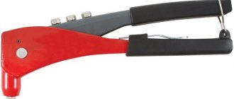
Hand rivets
One of the simplest and most actively used types of rivets, most often used for those connections that will not be disassembled in the future.
Riveting process:
- A hole is created where the rivet is placed.
- The recess houses the head of the rivet.
- Using a hammer, the surfaces are pressed tightly.
- The second head is flared with circular blows of the tool, giving the desired shape.
Types of rivets (by head shape):
- with a convex head. Diameter 1-36 mm; length 2-180 mm.
- with a hidden head. Diameter 1-36 mm; length 2-180 mm.
Types of work : fastening visible plates, thin sheets of metal, etc.
Disadvantage: accessibility to both sides of the parts being connected is required; complexity of riveting.
Tubular, semi-tubular and piston rivets
Due to their fragility, this type of rivet is used for joining parts subject to slight physical stress.
These parts are hollow: tubular without a cap and with a through hole; half-tubular, half-hollow; piston with thin-walled tubes.
Riveting process:
- A hole is created where the rivet is placed.
- It is riveted with punches.
- The connection is ready.
Disadvantage: can only be used with little physical activity, accessibility to both sides is required.
Mortgage rivets
These rivets compare favorably with the previous ones in their strength. This is due to the fact that a punch remains in their base after installation.
Riveting process:
- A hole is drilled where the rivet is placed.
- A punch is placed inside the rivet so that it comes out on the opposite side.
- The rivet material is riveted.
- A cap is formed.
Types of work : thick-walled structures with increased rigidity.
Threaded rivet
A threaded rivet is necessary for making a threaded connection in materials with a light texture, where creating threads in the parts themselves is impossible due to their small thickness, for example, in sheet metal. A threaded rivet contains threads inside that are used during connection to the surface of the rivet. Although its main use is to create a bolted connection.
Riveting process:
- A hole is made.
- The part is carefully screwed onto a tool prepared for this work, then placed in the created hole.
- With the help of a riveter, the rivet is compressed along its entire length, pressing the parts tightly on both sides.
- The tool is turned inside out.
The material of the rivet must be identical to the material of the parts being connected.
Types of work : decorative activities; surfaces where wear resistance to corrosion processes is considered extremely necessary.
Blind rivets
The proposed type of rivets is widely used for joining various materials, especially fragile ones.
Riveting process:
- A hole is created.
- The rivet is carefully inserted onto a specialized tool, then placed in the recess.
- The tool pulls the rod and compresses it along its length.
- The tool is removed simultaneously with the rod.
Material : aluminum, steel, combined version.
Types of rivets , depending on the shape of the side:
- With standard;
- With wide;
- With a secret one.
Types of work : universal.
Safety rules for riveting
- The special hammer must fit tightly onto the handle.
- The crimps and strikers must be free of cracks and gouges.
- It is better to do the work in pairs, as this facilitates an already labor-intensive process.
- Cutouts for supports must be present, and the support itself must be 4-5 times heavier than the hammer.
If a defect occurs during work, the damaged part is cut off with a jamb chisel. If necessary, use not only a hammer, but also a sledgehammer. After this, the rivet rod is knocked out with a beard.
These stages of working on a defective product are not suitable for parts made from thin sheets, since cutting off the rivet head can lead to deformation of the part. In this case, it would be more appropriate to use the drilling method.
It should be noted that the scope of riveting is narrowing every year, as welding methods are improved. But even today the scope of application is quite wide: aircraft and shipbuilding, building structures, mechanical engineering, etc.
| Attention Bearing Buyers Dear customers, send your questions and requests for the purchase of bearings and components by email or call now: Delivery of bearings throughout the Russian Federation and abroad. Bearing catalog on the website |
Attention Bearing Buyers
Dear customers, send your questions and requests for the purchase of bearings and components by email or call now: +7 [email protected] Delivery of bearings in the Russian Federation and abroad. Bearing catalog on the website
themechanic.ru
About metalworking
Processing of threaded surfaces is an operation that is carried out by removing a layer of material (chips) from the machined surface or without removing chips, i.e., plastic deformation. In the first case, we are talking about cutting a thread, and in the second, about rolling it. When assembling and repairing equipment and carrying out installation work, cutting or rolling threads is used manually or using hand-held mechanized tools.
A threaded rod that has a screw surface along its entire length or some part of it is called a screw , and a hole that has a screw surface is called a nut .
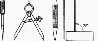
Thread elements (Fig. 1) are certain numerical parameters that characterize the thread.
Thread pitch P is the distance in millimeters between the tops of two adjacent threads, measured parallel to its axis.
Profile height H is the distance from the top of the thread to the base of the profile, measured in the direction perpendicular to the thread axis.
Rice. 1. Elements of triangular thread: α - profile angle; P - thread pitch; d is the outer diameter of the thread; d1 - internal thread diameter; d2 - average thread diameter; H - thread profile height
Rice. 3.24. Elements of triangular thread: a - profile angle; P - thread pitch; d is the outer diameter of the thread; d1 - internal thread diameter; d2 - average thread diameter; H - thread profile height
Profile angle α is the angle between the straight sections of the sides of the thread profile.
The outer diameter of the thread d is the largest diameter of the thread, which is measured along its tops in a direction perpendicular to the axis.
The internal diameter of a thread is the smallest distance between opposing thread roots, measured perpendicular to the axis.
The average thread diameter d2 is the diameter of a conditional circle drawn in the middle of the thread profile between the bottom of the recess and the top of the protrusion, measured in the direction perpendicular to the axis.
Tools and devices for cutting external and internal threads by hand. To cut external and internal threads manually, special thread-cutting tools (taps and dies) and devices are used to create the torque on the tool necessary to provide cutting forces during the processing process.
The tap (Fig. 2) consists of two parts: the working part, which ensures the cutting process, and the tail, at the end of which there is a square protrusion for installing the driver. The working part of the tap includes a cutting (taking) part, which ensures the removal of the main allowance for processing, and a calibrating part, which carries out the final processing of the thread. Taps for manual threading are made in the form of sets of two or three pieces (rough, medium and finishing), which are marked with circular marks on the tail part (one, two and three marks, respectively).
Rice. 2. Tap: 1 - thread (turn); 2 - square; 3— shank; 4 - groove
To create torque on the cutting tool (tap), special devices are used - wrenches of various designs.
The universal driver (Fig. 3) is a frame with two crackers - movable and fixed, forming a square hole and securing the tail part of the tap.
Rice. 3. Sliding knob: 1 - frame; 2 - coupling; 3 - handle; 4, 5 - movable and fixed cracker, respectively; a is the side of the square
A driver with switching cams (safety) (Fig. 4, a) allows you to protect the tap from breakage by disengaging the cams of the body and bushing when the force transmitted by the driver exceeds the permissible value.
The end driver (Fig. 4, b) is used when cutting threads in hard-to-reach places, as it allows you to work with one hand.
A ratchet driver (Fig. 4, c) is used for cutting threads in hard-to-reach places, when the driver can be turned at a small angle at a time.
Rice. 4. Gates: a - safety: 1 - body; 2 - bushing; 3 - spring; b - end; c - with ratchet
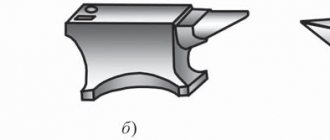
A die is a tool for cutting external threads, consisting of two parts: a tapping and a calibrating one. Their purpose is the same as that of the corresponding parts of the working part of the tap. When manually cutting threads, dies of various designs are used.
Round dies (Fig. 5, a) are a threaded ring with several grooves for forming cutting edges and removing chips. They are made whole and cut. Due to their springy properties, the dies allow you to adjust the average diameter of the thread being cut.
Square dies (Fig. 5, b) consist of two halves, which are secured in a special frame with handles - a clamp.
The clamp provides the ability to regulate the average diameter of the thread being cut.
Rice. 5. Threading dies: a - round: 1 - intake part; 2 - calibrating part; 3 - chip groove; b - square (sliding): 1 - die; 2 - die
To create a torque and ensure the cutting process when cutting external threads with dies, special devices are used - cranks (for round dies) and clamps (for split dies).
The driver for round dies (Fig. 6) is a round frame with a recess in which a round die is placed, held from turning by three locking screws. The fourth screw allows you to adjust the average diameter of the thread when using a split round die to cut it.
Rice. 6. Driver for round dies.
The die (see Fig. 5, b) is a square frame with protrusions into which the grooves of the die fit. One of the halves of the die can be moved using a screw, adjusting the average diameter of the thread being cut.
Hand-held power tools for cutting internal threads can be equipped with either a pneumatic or an electric drive.
A pneumatically driven thread cutter (Fig. 7) is designed for cutting small diameter threads. The pneumatic motor 1 rotates the spindle 4. When you press the handle 3 of the housing, threading occurs. When the pressure on handle 3 is released, the spindle 4 moves under the influence of the spring and its movement is reversed. In this case, the tap 5 is rapidly unscrewed from the hole in the workpiece 6. The tool is turned on by pressing the trigger 2.
Rice. 7. Thread cutter with pneumatic drive: 1 - pneumatic motor; 2 - trigger; 3 - handle; 4 - spindle; 5 - tap; 6 - blank
Electrically driven thread cutter (Fig. equipped with a built-in electric motor, reversing mechanism and gearbox.
Rice. 8. Electrically driven thread cutter
Preparing rods and holes for threading. During the thread cutting process, not only the removal of a layer of material from the surface of the workpiece occurs, but also plastic deformation of the machined surface, which is accompanied by the extrusion of part of the workpiece metal from the recesses of the thread turns to the tops. This phenomenon must be taken into account when determining the diameters of rods and holes for threading. Therefore, it is advisable to determine the dimensions of the workpieces using reference tables, in which they are given taking into account all the factors affecting the cutting process.
In practice, the diameter of the hole for the thread is chosen equal to its nominal size, reduced by the pitch. For example, when cutting an M10 thread, the hole diameter should be 10 - 1.5 = 8.5 mm.
When cutting external threads, the diameter of the rod should be 0.1 ... 0.2 mm less than the nominal diameter of the thread, depending on its size.
When processing external and internal threads, it is necessary to adhere to a number of rules.
- Manual threading must be done with the tap or die generously lubricated with machine oil.
- When cutting threads by hand, you should periodically cut off the resulting chips by moving the tap or die back 1/2 turn.
- After cutting the thread, it is necessary to control its quality: by external inspection (avoiding scuffing and torn threads) and with a thread gauge, the bore of which should be screwed on easily, by hand.
The rules for cutting external threads manually are as follows.
- Before cutting the thread, check the diameter of the rod, which should be 0.1 ... 0.2 mm less than the nominal thread size.
- Make a chamfer at the top of the rod so that it is concentric with the axis of the rod. In this case, its diameter should not be less than the internal diameter of the thread, and the angle of inclination relative to the axis of the rod should be 60°.
- The rod should be firmly secured in the vice, checking its perpendicularity to the clamping jaws using a square.
The rules for processing internal threads manually are as follows.
- Check that the diameter of the hole matches the size of the thread being cut.
- Check that the hole depth meets the drawing requirements when cutting blind threads.
- Using a square, check that the tap axis is perpendicular to the plane of the workpiece in the hole of which the thread is being cut.
- Use all taps in the set when cutting threads.
- Periodically clean blind holes from chips when cutting threads into them.
Threading on pipes is carried out using special tools - clamps and thread-cutting dies.
A die with sliding dies (Fig. 9) is a device most often used for cutting external threads on pipes. The die is equipped with a set of sliding dies for cutting threads with a diameter of 1/2…3/4; 1…11/4; and 11/2…2″. The clamp is mounted in such a way that four dies 5 moving in its body 1 can simultaneously approach the center or diverge from it. The movement of the dies is ensured by a special rotary device driven by a handle 4. The precise installation of the dies to the size of the thread being cut is carried out using a dial located on the body, and the installation movements are carried out by a worm gear 3. After installation, the position of the dies is fixed with a special device - a “pawl”. The cutting force is transmitted to the tool using handles 2.
Rice. 9. Jig for cutting pipe threads: 1 - body; 2 — handles; 3 - worm gear; 4 — handle for moving dies; 5 - dies
A round thread-cutting comb (Fig. 10, a) is used for cutting pipe threads on lathes and drilling machines. Combs are produced in sets of four. Thread cutting is carried out using a special self-opening screw-cutting head (Fig. 10, b).
Rice. 10. Round thread-cutting comb (a) and self-opening head for attaching it (b)
To facilitate the operation of the tool and improve the quality of threads obtained when cutting threads, COTS is used. Their choice depends on the material of the workpiece being processed. For example, an emulsion is used to cool steel workpieces (structural, tool and alloy steel). Kerosene should be used to cool cast iron and aluminum. Threading in copper, brass and bronze workpieces can be done without cooling.
Disadvantages of riveted joints [edit | edit code]
- The complexity of the process. It is necessary to drill many holes, install rivets, and rivet them. These operations are performed manually by two assembly fitters. Until the last quarter of the 20th century in the USSR, aircraft factories specially hired thin young men who were able to fit into a narrow compartment in order to hold the support anvil there.
- Increased material consumption of the connection. The rivet seam weakens the main part, so it needs to be thicker. The load is carried by the rivets, so their cross-section must correspond to the load.
- The need for special measures for sealing. This is very important for aircraft construction and rocketry, when assembling caisson tanks and passenger compartments. Caisson tanks located in the wings of aircraft usually contain fuel—aviation kerosene. Kerosene-resistant rubber sealant should cover all rivet seams. Its weight can be tens of kilograms.
- The process is accompanied by noise and vibration. This leads to a number of occupational diseases among pickers and causes deafness. Therefore, wherever possible, new riveting tools are being introduced.
Advantages of riveted connections [edit | edit code ]
- Does not allow fatigue cracks to propagate, thus increasing the reliability of the entire product.
- Allows joining materials that cannot be welded.
Recently, these advantages have been offset by the fact that sufficiently strong alloys that can be welded have appeared, and synthetic adhesives have appeared that make it possible to obtain a strength in the adhesive joint no worse than that of the base material. Aluminum alloys have been replaced by composites, into which metal embedded elements are glued at the manufacturing stage.