Pencils and sheets of whatman paper are gradually becoming a thing of the past, giving way to digital technologies and specialized programs. But the principles of drawing remain the same and it is necessary to learn to read drawings. In production and in construction organizations, the use of design documentation is widespread, which is impossible to develop without knowledge of drawing. To create simple and complex pipelines and electrical installations, for assembly units and high-rise metal structures, it is still necessary to create projects.
9.1. The concept of types of products and design documents
A product is any item or set of production items to be manufactured at an enterprise.
GOST 2.101-88* establishes the following types of products:
- Details;
- Assembly units;
- Complexes;
- Kits.
When studying the Engineering Graphics course, two types of products are offered for consideration: parts and assembly units.
A part is a product made from a material that is homogeneous by name and brand, without the use of assembly operations.
For example: a bushing, a cast body, a rubber cuff (unreinforced), a piece of cable or wire of a given length. Parts also include products that have been coated (protective or decorative), or manufactured using local welding, soldering, and gluing. For example: a body covered with enamel; chrome-plated steel screw; a box glued together from one sheet of cardboard, etc.
Assembly unit is a product consisting of two or more component parts connected to each other at the manufacturer by assembly operations (screwing, welding, soldering, riveting, flaring, gluing, etc.). For example: machine tool, gearbox, welded body, etc.
Complexes are two or more specified products not connected at the manufacturing plant by assembly operations, but intended to perform interrelated operational functions, for example, an automatic telephone exchange, an anti-aircraft complex, etc.
Kits are two or more specified products that are not connected at the manufacturing plant by assembly operations and represent a set of products that have a general operational purpose of an auxiliary nature, for example, a set of spare parts, a set of tools and accessories, a set of measuring equipment, etc.
The production of any product begins with the development of design documentation. Based on the technical specifications, the design organization develops a preliminary design containing the necessary drawings of the future product, an explanatory note, and analyzes the novelty of the product, taking into account the technical capabilities of the enterprise and the economic feasibility of its implementation.
The preliminary design serves as the basis for the development of working design documentation. A complete set of design documentation determines the composition of the product, its structure, the interaction of its components, the design and material of all its parts and other data necessary for the assembly, manufacture and control of the product as a whole.
Assembly drawing is a document containing an image of an assembly unit and the data necessary for its assembly and control.
A general drawing is a document that defines the design of a product, the interaction of its components and the principle of operation of the product.
Specification is a document defining the composition of an assembly unit.
The general drawing has the assembly unit number and SB code.
For example: assembly unit code (Figure 9.1) TM.0004ХХ.100 SB the same number, but without a code, has a specification (Figure 9.2) of this assembly unit. Each product included in the assembly unit has its own position number indicated on the general view drawing. By the position number in the drawing you can find in the specification the name, designation of this part, as well as the quantity. In addition, the note may indicate the material from which the part is made.
Basic rules for reading drawings
Any rack or fastener is first embodied on a sheet of paper or computer screen and only then transferred to the production workshop. To correctly understand the task, so that the responsible employee can understand exactly where the welding seams should be applied or a hole of the required diameter should be made, one must be able to read technological documents.
In mechanical engineering, drawings can be different: there are drawings of parts, assembly drawings, diagrams, specifications, etc. Technical drawings must be made in accordance with the rules of state standards (GOST) or the Unified System of Design Documentation (ESKD).
The number of images should be minimal. In engineering graphics, a drawing is a representation of an object using projections and the exact ratio of its dimensions.
9.2. Sequence of execution of drawings of parts
A part drawing is a document containing an image of the part and other data necessary for its manufacture and control.
Before completing the drawing, it is necessary to find out the purpose of the part, design features, and find mating surfaces. On the training drawing of the part, it is enough to show the image, dimensions and grade of material.
When drawing a part, the following sequence is recommended:
- Select the main image (see section 2).
- Set the number of images - views, sections, sections, extensions that clearly give an idea of the shape and size of the part, and supplement the main image with any information, remembering that the number of images in the drawing should be minimal and sufficient.
- Select the image scale according to GOST 2.302-68. For images on working drawings, the preferred scale is 1:1. The scale in the part drawing does not always have to match the scale of the assembly drawing. Large and simple details can be drawn on a reduction scale (1:2; 1:2.5; 1:4; 1:5, etc.), small elements are best depicted on an enlargement scale (2:1; 2.5 :1; 4:1; 5:1; 10:1; etc.).
- Select drawing format. The format is selected depending on the size of the part, number and scale of images. Images and inscriptions should occupy approximately 2/3 of the working area of the format. The working field of the format is limited by a frame in strict accordance with GOST 2.301-68* for the design of drawings. The main inscription is located in the lower right corner (on A4 format the main inscription is located only along the short side of the sheet);
- Layout the drawing. To rationally fill out the format field, it is recommended to outline the overall rectangles of the selected images with thin lines, then draw the axes of symmetry. The distances between the images and the format frame should be approximately the same. It is selected taking into account the subsequent application of extension, dimension lines and corresponding inscriptions.
- Draw the detail. Apply extension and dimension lines in accordance with GOST 2.307-68. After drawing the part with thin lines, remove the extra lines. Having chosen the thickness of the main line, trace the images, observing the ratios of the lines in accordance with GOST 3.303-68. The outline must be clear. After tracing, complete the necessary inscriptions and put down the numerical values of the dimensions above the dimension lines (preferably font size 5 according to GOST 2.304-68).
- Fill out the title block. In this case, indicate: the name of the part (assembly unit), the material of the part, its code and number, who and when the drawing was made, etc. (Figure 9.1)
Stiffening ribs and spokes are shown unshaded in longitudinal sections.
Figure 9.1 – Working drawing of the “Case” part
Drawings and 3D models of metalworking equipment
Classification of metal-cutting machines, their types and types
Units for processing metal products are divided into nine large groups. In accordance with this division they can be:
- turning (group code – 1);
- boring and drilling (code – 2);
- finishing, grinding, sharpening and polishing (code – 3);
- special (code – 4);
- thread- and gear-processing (code – 5);
- milling (code – 6);
- split (code – 7);
- slotting, planing, lingering (code – 8);
- different (code – 9).
The units of each group, in addition, are usually divided into different types:
- lathes: multi- and single-spindle, as well as specialized (a subgroup of semi-automatic and automatic machines), revolving, multi-cutting copying, rotary, drilling and cutting, special, frontal;
- boring and drilling metal-cutting machines: semi-automatic multi- and single-spindle, vertical, radial and horizontal drilling, coordinate, diamond and horizontal boring, various drilling machines;
- polishing and other installations of the third group: roughing, internal, cylindrical and surface grinding, sharpening, specialized;
- units for processing teeth and threads: gear hobbing, gear cutting (their device allows processing conical wheels), gear cutting (cylindrical wheels), thread cutting, thread and gear grinding, checking and gear finishing, thread milling, for working with the ends of teeth, for worm machines steam;
- metal-cutting milling machines: continuous, cantilever (vertical, wide-universal and horizontal), longitudinal, non-cantilever vertical, engraving and copying;
- planing and similar equipment: longitudinal with two or one stand, broaching (horizontal and vertical), transverse planing, slotting;
- cutting units: with a smooth disk, with an abrasive wheel, with a cutter, saws (hacksaw, disk, band), straightening and cutting;
- various metal-cutting machines: dividing units, for monitoring grinding wheels and drills, balancing, filing, centerless and straightening, tangential sawing.
In addition, the equipment we are interested in is divided into the following types:
- by geometric dimensions and weight: large, unique and heavy;
- by level of specialization: special (metal-cutting machines for working with products of the same standard sizes), specialized (the sizes of the processed parts are different, but they belong to the same type), universal (allow you to work with any products);
- in terms of accuracy: P (increased accuracy), N (normal), A (especially high), B (high), and also C (precision), the latter units are also often called particularly accurate.
Marking of units for metal processing
As you yourself understand, the classification to which metal-cutting machines are subject was invented for a reason, but so that a specialist can instantly determine the type, basic structure and operating features of the machine, the symbol of which he sees in front of him.
The marking of different machine models is a few numbers and letters, which encrypt basic information about the unit. The first number indicates the group of the machine, the second – its type, the third (sometimes also the fourth) – the standard size.
If any letter appears at the end of the code (after all the numbers), it tells us about certain special characteristics of the machine, its level of accuracy, or that the equipment has been modified. But the letter after the very first digit in the marking of a metal processing unit indicates that it has undergone modernization (or it is a different version of it, different from the basic version).
To make the coding principles clear to you, let’s decipher the markings of the 6M13P machine. By the first digit we can easily determine that it is milling, classified as the first type of milling equipment (number 1), has a 3rd standard size, belongs to high-precision units (the last letter in the code), and has been modernized (the first letter after the first letter).
Level of automation and other equipment features
Metal-cutting machines used for mass and large-scale production are called aggregate machines. Their structure is approximately the same; they are produced using standardized work tables, work heads, beds, spindles and other components. If machines are manufactured for single and small-scale production, their design may be unique.
According to the level of automation, the units we are considering are:
- Semi-automatic. They install the workpiece to be processed, start up the equipment, and dismantle the product after processing by a person. The remaining procedures, classified as auxiliary, are performed automatically.
- Automatic. Such machines need to be set up (set the necessary conditions for processing a particular batch of products) and launched. They will perform all work operations themselves.
CNC machines (computer numerical control) deserve special mention. Their work is “guided” by a special program containing a coded complex of numerical values. Such a program sets all the working operations of the machine, starting from the rotation speed of its working tool and ending with the speed of execution of a specific process.
Modern CNC systems contain the following mandatory elements:
- Operator console (console). It makes it possible to enter a program, transfer metal-cutting machines to manual operation mode, set equipment operating modes, and so on.
- Controller. A special device on CNC units that sets and monitors the accuracy of technological control commands, the trajectory of movement of the working device, is responsible for changes and general control of the machine, and also performs additional calculations. These days, a controller can be a powerful industrial computer, a logical programmable device, or a conventional microprocessor.
- Operator panel (screen, display). This CNC element is designed so that the specialist working at the machine can visually observe the process of processing products, and, if necessary, make any changes to the control program.
The essence of operating CNC equipment is relatively simple. First, a control program is compiled for metal-cutting equipment, which is entered into the controller by the operator (a programmer is used for these purposes). When the unit is turned on, the CNC issues sequential commands to the machine components. After completing all commands for processing the part, the equipment turns off.
The high accuracy and speed of performing work operations, which characterize metal-cutting machines equipped with CNC, have led to their active use as part of automatic workshop lines and very large production automated systems.
Brief information about the design of metal-cutting units
The machines of different groups and types that we describe have many common features in their design. Their design is based on the fact that all technical devices and mechanisms installed on the units must guarantee the ability to perform two movements:
- feeding the cutting device or workpiece;
- direct cutting movements.
To ensure the indicated movements, as well as the stable operation of all equipment, a metal cutting machine must have the following structural elements:
- controls (responsible for starting the unit and stopping it, necessary for constant monitoring of the operation of the machine);
- transmission device (it is needed to transmit movement from the engine to the actuator and to convert movement);
- drive (electric, mechanical, pneumatic, hydraulic);
- actuators (devices for cutting metal are placed on them; it is these mechanisms that carry out metal processing).
9.3. Applying dimensions
Dimensioning is the most critical part of working on a drawing, since incorrectly placed and extra dimensions lead to defects, and lack of dimensions causes production delays. Below are some recommendations for applying dimensions when drawing parts.
The dimensions of the part are measured using a meter on the drawing of the general view of the assembly unit, taking into account the scale of the drawing (with an accuracy of 0.5 mm). When measuring the largest thread diameter, it is necessary to round it to the nearest standard, taken from the reference book. For example, if the diameter of a metric thread is measured to be d = 5.5 mm, then it is necessary to accept an M6 thread (GOST 8878-75).
9.3.1. Size classification
All sizes are divided into two groups: basic (conjugate) and free.
The main dimensions are included in the dimensional chains and determine the relative position of the part in the assembly; they must ensure:
- location of the part in the assembly;
- precision of interaction of assembled parts;
- assembly and disassembly of the product;
- interchangeability of parts.
An example is the dimensions of the female and male elements of mating parts (Figure 9.2). The common contacting surfaces of the two parts have the same nominal size.
Free dimensions are not included in the dimensional chains of the part. These dimensions determine those surfaces of the part that do not connect with the surfaces of other parts, and therefore they are made with less accuracy (Figure 9.2).
A – covering surface; B – covered surface; B - free surface; d – nominal size Figure 9.2
9.3.2. Dimensioning methods
The following sizing methods are used:
- chain;
- coordinate;
- combined.
With the chain method (Figure 9.3), the dimensions are placed sequentially one after another. With this sizing, each roller step is processed independently, and the technological base has its own position. At the same time, the accuracy of the size of each element of the part is not affected by errors in the execution of previous dimensions. However, the total size error consists of the sum of the errors of all sizes. Drawing dimensions in the form of a closed chain is not permitted, except in cases where one of the dimensions of the chain is indicated as a reference. Reference dimensions in the drawing are marked * and written in the field: “* Dimensions for reference ” (Figure 9.4).
Figure 9.3
Figure 9.4
With the coordinate method, dimensions are set from selected bases (Figure 9.5). With this method, there is no summation of sizes and errors in the location of any element relative to one base, which is its advantage.
Figure 9.5
The combined sizing method is a combination of chain and coordinate methods (Figure 9.6). It is used when high precision is required in the manufacture of individual elements of a part.
Figure 9.6
According to their purpose, dimensions are divided into overall, connecting, installation and structural.
Overall dimensions determine the maximum external (or internal) outlines of the product. They are not always applied, but are often listed for reference, especially for large cast parts. The overall dimensions are not applied to bolts and studs.
Connecting and installation dimensions determine the dimensions of the elements by which this product is installed at the installation site or connected to another. These dimensions include: the height of the center of the bearing from the plane of the base; distance between hole centers; diameter of the circle of centers (Figure 9.7).
A group of dimensions that determine the geometry of individual elements of a part intended to perform a particular function, and a group of dimensions for elements of a part, such as chamfers, grooves (the presence of which is caused by processing or assembly technology), are performed with varying accuracy, therefore their dimensions are not included in one dimensional chain (Figure 9.8, a, b).
Figure 9.7
| Wrong | Right |
Figure 9.8, a
| Wrong | Right |
Figure 9.8, b
9.5. Making a drawing of a part that has the shape of a body of revolution
Parts that have the shape of a body of rotation are found in the vast majority (50-55% of the original parts) in mechanical engineering, because rotational movement is the most common type of movement of elements of existing mechanisms. In addition, such parts are technologically advanced. These include shafts, bushings, disks, etc. processing of such parts is carried out on lathes, where the axis of rotation is located horizontally.
Therefore, parts having the shape of a body of rotation are placed on the drawings so that the axis of rotation is parallel to the main inscription of the drawing (stamp). It is advisable to place the end of the part, taken as the technological base for processing, on the right, i.e. the way it will be positioned during processing on the machine. The working drawing of the bushing (Figure 9.9) shows the execution of a part that is a surface of rotation. The outer and inner surfaces of the part are limited by surfaces of rotation and planes. Another example could be the “Shaft” part (Figure 9.10), limited by coaxial surfaces of rotation. The center line is parallel to the title block. Dimensions are given in a combined way.
Figure 9.9 - Working drawing of a part of the surface of rotation
Figure 9.10 — Working drawing of the “Shaft” part
Symbols on the drawings of technological documentation
The drawings use symbols established by state standards. These are the basics; they describe the rules for designing signs, letters, numbers, lines, and so on.
Usually they are not explained in the drawing, with the exception of symbols in which it is necessary to indicate the standard number. Still, it is necessary to familiarize yourself with GOSTs to execute and recognize drawings or diagrams.
This is exactly the case when simply reading a drawing textbook is not enough. It is best to take specialized courses or study engineering or other professions related to manufacturing or construction.
The ability to read technological documentation is necessary for both an engineer and an ordinary turner.
In general, mechanical engineering and other industries use a number of basic designations:
- Letter
, reflecting conventional quantities, for example, radius, thread pitch and much more.
- Digital
, expressing size values, angle values, etc.
- Alphanumeric
, found mainly in electrical circuits.
- Graphic
– these are the basic elements of technical drawing. They display both the structure of the part, the material of the product, and its design (door or window opening, etc.).
All this is necessary for the correct presentation of the minimum information on the sheet and its subsequent correct reading.
9.6. Making a drawing of a part made from sheet metal
This type of parts includes gaskets, covers, strips, wedges, plates, etc. Parts of this shape are processed in various ways (stamping, milling, planing, cutting with scissors). Flat parts made of sheet material are usually depicted in one projection, defining the contour of the part (Figure 9.11). The thickness of the material is indicated in the title block, but it is recommended to indicate it again on the image of the part, on the drawing - s3 . If the part is bent, then a development is often shown in the drawing.
Figure 9.11 - Drawing of a flat part
9.7. Execution of a drawing of a part manufactured by casting, followed by machining
Molding by casting allows you to obtain a fairly complex shape of a part, with virtually no loss of material. But after casting, the surface turns out to be quite rough, therefore, the working surfaces require additional mechanical processing.
Thus, we get two groups of surfaces - casting (black) and processed after casting (clean). The casting process: molten material is poured into the casting mold, after cooling the workpiece is removed from the mold, for which most of the surfaces of the workpiece have casting slopes, and the mating surfaces have casting rounding radii.
Casting slopes need not be depicted, but casting radii must be depicted. The dimensions of the casting radii of roundings are indicated in the technical requirements of the drawing by writing, for example: Unspecified casting radii 1.5 mm.
The main feature of applying dimensions: since there are two groups of surfaces, that is, two groups of sizes, one connects all black surfaces, the other connects all clean surfaces, and for each coordinate direction it is allowed to put down only one size, connecting these two groups of sizes.
In Figure 9.12, these dimensions are: in the main image - size of the cover height - 70, in the top view - size 10 (from the lower end of the part) (highlighted in blue).
When casting, a casting material is used (letter L in the designation), which has increased fluidity, for example:
- steel according to GOST 977-88 (Steel 15L GOST 977-88)
- gray cast iron according to GOST 1412-85 (SCh 15 GOST 1412-85)
- casting brass according to GOST 17711-93 (LTs40Mts1.5 GOST 17711-93)
- aluminum alloys according to GOST 2685-75 (AL2 GOST 2685-75)
Figure 9.12 - Drawing of a casting part
9.8. Drawing a spring
Springs are used to create certain forces in a given direction. According to the type of loading, springs are divided into compression, tension, torsion and bending springs; in shape - for screw cylindrical and conical, spiral, sheet, disc, etc. rules for the execution of drawings of various springs are established by GOST 2.401-68. In the drawings, springs are drawn conventionally. The coils of a helical cylindrical or conical spring are depicted by straight lines tangent to sections of the contour.
It is allowed to depict only sections of turns in a section. Springs are shown with right-hand winding, with the true direction of the coils indicated in the technical requirements. An example of a training drawing of a spring is shown in Figure 9.13.
To obtain flat bearing surfaces on the spring, the outer turns of the spring are pressed by 3/4 of a turn or by a whole turn and ground. The pressed turns are not considered working, therefore the total number of turns n is equal to the number of working turns plus 1.5÷2: n1=n+(1.5÷2) (Figure 9.14).
The construction begins by drawing axial lines passing through the centers of the sections of the spring coils (Figure 9.15, a). Then a circle is drawn on the left side of the center line, the diameter of which is equal to the diameter of the wire from which the spring is made. The circle touches the horizontal line on which the spring rests. Then you need to draw a semicircle from the center located at the intersection of the right axis with the same horizontal line. To construct each subsequent coil of the spring, sections of the coils are constructed on the left at a step distance. On the right, each section of the coil will be located opposite the middle of the distance between the coils built on the left. By drawing tangents to the circles, a cross-sectional image of the spring is obtained, i.e. image of the coils lying behind the plane passing through the axis of the spring. To depict the front halves of the turns, tangents to the circles are also drawn, but with a rise to the right (Figure 9.15, b). The front quarter of the support turn is constructed so that the tangent to the semicircle simultaneously touches the left circle in the lower part. If the wire diameter is 2 mm or less, then the spring is depicted with lines 0.5÷1.4 mm thick. When drawing helical springs with a number of turns of more than four, show one or two turns at each end, in addition to the support ones, drawing axial lines through the centers of the sections of the turns along the entire length. In working drawings, helical springs are depicted so that the axis has a horizontal position.
As a rule, a test diagram showing the dependence of deformations (tension, compression) on load (P1; P2; P3) is placed in the working drawing, where H1 is the height of the spring at preliminary deformation P1; H2 – the same, at working deformation P2; H3 – height of the spring at maximum deformation P3; H0 is the height of the spring in working condition. In addition, under the image of the spring indicate:
- Spring standard number;
- Winding direction;
- n – number of working turns;
- Total number of turns n;
- Length of the unrolled spring L=3.2×D0×n1;
- Dimensions for reference;
- Other technical requirements.
On training drawings, it is recommended to indicate paragraphs from the listed points. 2,3,4,6. The execution of the test diagram is also not provided for when completing the training drawing.
Figure 9.13 – Working drawing of the spring
| A | b |
Figure 9.14. Images of preloaded spring coils
Figure 9.15. Sequence of constructing an image of a spring
DRAWINGS OF PARTS MADE ON LATING AND MILLING MACHINES
METHODOLOGICAL
DEVELOPMENT
LESSON
In the subject "Technology" for boys
7th grade
Topic: “DRAWINGS OF PARTS MADE ON LATING AND MILLING MACHINES”
Technology teacher Alekseenko Fedor Leonidovich.
LESSON PLAN
Purpose: To familiarize students with the rules for making drawings of parts made on lathes and milling machines.
During the classes
- Organizing time.
- Repetition of covered material.
1.Front written survey on previous topics.
1.What is technical drawing? (A visual image of an object, made by hand, observing the proportions between parts of the object)
2.What is a drawing? (Conventional image of an object, made using drawing tools in compliance with the exact scale)
3.What does graphic documentation include? ( Drawings, sketches, technical drawings)
4.What is a sketch? (Conventional image of an object, made by hand without maintaining an exact scale)
5.What is the difference between a sketch and a drawing? (The sketch is done by hand without observing an exact scale, and the drawing is done using drawing tools in compliance with an exact scale. There are several views in the drawing: front, left, top, etc.)
6.What types of drawing tools are there? (Cutting tools, compasses, squares, crossbars, etc.)
2. Statement of the topic and purpose of the lesson.
3. Presentation of new material.
3. Presentation of new material.
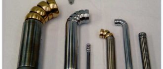
When manufacturing parts on lathes and milling machines, they use the same graphic documentation
as in the manufacture of parts from rolled products: drawings, sketches, technical drawings (Fig. 1).
Rice.
1. Products made on lathes and milling machines: a – knob; 1 – clamp; 2 - handle; b - punch;
c - jig for drilling holes
However, these parts often have internal surfaces (grooves, holes), the shape of which cannot be determined from the view shown in the drawing. To define internal surfaces, cutting planes are used,
with the help of which the part is mentally cut and images called sections and sections are obtained (Fig. 2).
Rice. 2.
Obtaining a section and section: a - part with a cutting plane; b - dissected part; c - drawing of the part; g - section; d - section
On the cross section
show only what is located directly in the cutting plane (Fig. 2, e).
A section is
an image of a dissected part showing what is in the cutting plane and what is located behind it (Fig. 2, d). The section, like the section, is hatched.
Hatching
applied only in those places where the cutting plane cuts the part.
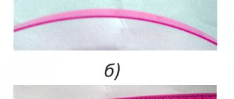
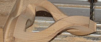
For metal products, shading with thin solid lines is used at a short distance from each other at an angle of 45° (Fig. 3, a). Non-metals (for example, plastics) are hatched crosswise (Fig. 3, b), wood - as shown in Fig. 3, c.
Parts made on lathes and milling machines are often cylindrical, conical or spherical in shape and are called bodies of revolution.
The drawings of these parts are characterized by an axial dash-dotted line passing through the axis of rotation (Fig. 3, c).
The end edges of rotating parts are usually cut to a cone and a chamfer is formed.
The chamfer facilitates the assembly of parts and protects the hand of the turner or assembler from cuts. The chamfer designation is shown in Fig. 4. Number 1 shows the height of the chamfer (in mm), and the number 45° indicates the angle at which it is cut.
The knob on the handle on the right (Fig. 4) shows the outer
thread MB.
The letter M indicates that the thread is metric,
and the number indicates that the outer diameter of the thread is 6 mm.
If we mentally cut a metric thread with a cutting plane passing through the axis of rotation of the part, then in the section we will see the thread profile
in the form of triangular protrusions and depressions with an apex angle of 60°.
In Fig. 4, a shows the internal
thread in the knob parts.
Rice. 3.
Types of shading of parts in sections and sections: a - metals and hard alloys; b - non-metallic materials; c – wood
Rice. 4.
Knob handle (see Fig. 1)
Threaded connections of parts are very common in technology: a vice is attached to a workbench with bolts and nuts, the tension of the hacksaw blade is adjusted using a nut and a movable threaded head, etc.
- Lesson summary.
Evaluation of completed work.
The teacher notes the most successfully completed work and draws attention to characteristic shortcomings.
Questions and tasks
- What is the difference between a section and a section?
- What is the purpose of a cutting plane?
- What is graphical documentation?
- How is a section hatched on a drawing of a plastic part?
- What is a body of revolution?
- How is a chamfer indicated on a drawing? What is a thread profile?
Homework: Compose a crossword puzzle on the topic covered.
9.9. Making a gear drawing
A gear is an important component of many designs of devices and mechanisms designed to transmit or transform motion.
The main elements of a gear wheel: hub, disk, ring gear (Figure 9.16).
Figure 9.16 — Gear elements
The tooth profiles are normalized by the relevant standards.
The main parameters of the gear are (Figure 9.17): m=P t
/ π [
mm
] – module;
d a
=
m st
(
Z
+2) – diameter of the circle of the tops of the teeth;
d
=
m st Z
– pitch diameter;
d f
=
m st
(
Z
– 2.5) – diameter of the circle of the depressions;
S t
= 0.5 m
st
π – tooth width; ha – height of the tooth head; hf – height of the tooth stem; h = ha+hf – tooth height; Pt – dividing circumferential step.
Figure 9.17 — Gear parameters
The main characteristic of the ring gear is the modulus - a coefficient that relates the circumferential pitch to the number π.
The module is standardized (GOST 9563-80). m = Pt / π [mm] Table 9.1 - Basic norms of interchangeability. Gear wheels. Modules, mm
| 0,25 | (0,7) | (1,75) | 3 | (5,5) | 10 | (18) | 32 |
| 0,3 | 0,8; (0,9) | 2 | (3,5) | 6 | (11) | 20 | (36) |
| 0,4 | 1; (1,125) | (2,25) | 4 | (7) | 12 | (22) | 40 |
| 0,5 | 1,25 | 2,5 | (4,5) | 8 | (14) | 25 | (45) |
| 0,6 | 1,5 | (2,75) | 5 | (9) | 16 | (28) | 50 |
On educational drawings of gears: Height of the tooth head – ha = m; Height of the tooth stem – hf = 1.25m; Roughness of tooth working surfaces – Ra 0.8 [µm];
At the top right of the sheet, a table of parameters is drawn up, the dimensions of which are shown in Figure 9.18; often only the modulus value, the number of teeth and the pitch diameter are filled in.
Figure 9.18 — Parameter table
Wheel teeth are depicted conventionally, according to GOST 2.402-68 (Figure 9.19). The dashed line is the dividing circle of the wheel.
In the section the tooth is shown uncut.
| A | b | V |
Figure 9.19 - Image of a gear wheel a - in section, b - in front view and c - in left view
The roughness on the lateral working surface of the tooth in the drawing is indicated on the pitch circle. An example of a gear drawing is shown in Figure 9.20.
Figure 9.20 — An example of a training drawing of a gear
9.10. Sequence of reading a general view drawing
- Using the data contained in the title block and the description of the product’s operation, find out the name, purpose and operating principle of the assembly unit.
- Based on the specification, determine which assembly units, original and standard products the proposed product consists of. Find in the drawing the number of parts indicated in the specification.
- Based on the drawing, represent the geometric shape, the relative position of the parts, how they are connected and the possibility of relative movement, that is, how the product works. To do this, it is necessary to consider in the drawing of the general view of the assembly unit all the images of this part: additional views, sections, sections, and extensions.
- Determine the sequence of assembly and disassembly of the product.
When reading a general view drawing, it is necessary to take into account some simplifications and conventional images in the drawings, allowed by GOST 2.109-73 and GOST 2.305-68*: In the general view drawing it is allowed not to show:
- chamfers, roundings, grooves, recesses, protrusions and other small elements (Figure 9.21);
- gaps between the rod and the hole (Figure 9.21);
- covers, shields, casings, partitions, etc. in this case, an appropriate inscription is made above the image, for example: “The cover pos. 3 is not shown”;
- inscriptions on plates, scales, etc. depict only the contours of these parts;
- in a cross-section of an assembly unit, different metal parts have opposite hatching directions, or different hatching densities (Figure 9.21). It must be remembered that for the same part, the density and direction of all hatchings are the same in all projections;
- the sections show, not dissected: the component parts of the product for which independent assembly drawings are drawn up;
- such parts as axles, shafts, fingers, bolts, screws, studs, rivets, handles, as well as balls, keys, washers, nuts (Figure 9.21);
Assembly drawings contain reference, installation, and as-built dimensions. Executive dimensions are dimensions for those elements that appear during the assembly process (for example, pin holes).
Figure 9.21 – Assembly drawing
Figure 9.22 – Specification
Designations on drawings in mechanical engineering
Tolerances and landings
Why is all this needed? This question arises not only among production workers. This is intended so that the factory does not waste time constantly measuring the actual dimensions of the received part, and produces compatible products without defects.
The numerical values of the upper and lower limit deviations are indicated next to the sizes in a smaller font than for the dimensional numbers. Tolerance is the range of deviation from the nominal size. The tolerance field is indicated by either one or two letters of the main deviation and a quality number.
The fit consists of a tolerance on the outer, male surface, a tolerance on the inner surface, and is determined by the amount of clearance or interference. Fit is indicated using a fraction on the right side of the size, the numerator indicates the maximum deviation, and the denominator has a similar designation for the compatible part.
Size designations
The size of the part is indicated by the corresponding numbers and lines with arrows at the ends. Dimension lines are continuous and parallel outside the outline of the part.
Units of measurement are not indicated on the drawings; by default, everything is indicated in millimeters.
Detail elements
There are times when it is more convenient to move and enlarge part of a part outside the main outline. In fact, these are the most difficult areas of the product in question. This is usually done with intricately shaped parts to save space on the drawing.
The complex part is outlined either in a circle or an oval and signed with a Roman numeral. The extension element of this fragment is assigned the same Roman number in the denominator, and its scale is indicated in the numerator.
Designation of materials in sections
A section is an image of a figure obtained after its conditional dissection. It shows only the shapes of the part, without revealing the other segments that are located behind it.
Sections can be extended or superimposed. The former are displayed outside the shape of the object, the latter directly on it.
The section contour is filled with oblique solid lines with an inclination angle of 45 degrees. The lines should be located in the same direction on all sections for one part, taking into account the material of the product.
They can be located anywhere in the drawing, at an arbitrary angle, but in this case with the addition of the word “rotated” above the section in the inscriptions.