Information about the manufacturer of the universal sharpening machine 3B642
The manufacturer of the universal sharpening machine 3B642 is Vitebsk sharpening machine plant Visas , founded in 1897.
Since 1940, the company has specialized in the production of sharpening equipment and today is the only manufacturer in the CIS of machines for the manufacture and sharpening of any cutting tool. The plant's products are used in more than sixty countries around the world.
Machines produced by the Vitebsk sharpening machine plant, Visas
- 3A64
- universal sharpening machine Ø 250 x 650 - 3A64M
- universal sharpening machine Ø 250 x 650 - 3A64D
- universal sharpening machine Ø 250 x 600 - 3A662
- semi-automatic grinding machine for hob cutters Ø 200 x 280 - 3B642
- universal sharpening machine with hydraulic drive Ø 250 x 630 - 3B642
- universal sharpening machine Ø 250 x 630 - 3D641E
universal sharpening machine with hydraulic drive Ø 200 x 400 - 3D642E
- universal sharpening machine with hydraulic drive Ø 250 x 630 - 3D692
- universal sharpening machine for circular saws, semi-automatic Ø 275..1430 - 3E642
- universal sharpening machine Ø 250 x 630 - 3E642E
- universal sharpening machine with hydraulic drive Ø 250 x 500 - 3E692
- universal sharpening machine for semi-automatic circular saws Ø 250..1430 - 3M642
- universal sharpening machine Ø 250 x 500 - 3662
— grinding machine for hob cutters, semi-automatic Ø 125 x 200 - VZ-318, VZ-318E
- universal sharpening machine Ø 200 x 500 - VZ-818, VZ-818E
- universal sharpening machine Ø 200 x 500 - VZ-319
– universal tabletop sharpening machine Ø 100 x 200 - BDS-4
- combined wood cutting machine - BDS-5
- combined wood cutting machine
Machine 3E642. Universal sharpening. Manual. Hydraulic equipment
This instruction manual for the “Universal sharpening machine 3E642” contains information necessary both for the maintenance personnel of this machine and for the employee directly involved in working on this machine. This manual is an electronic version in PDF format of the original paper version. This documentation contains the Manual (instructions) for operating the hydraulic equipment of the 3E642 universal sharpening machine.
CONTENT
Hydraulic circuit diagram Purpose of hydraulic equipment Design
Description of the hydraulic system Instructions for installation and operation
- Safety instructions
- Preparing the hydraulic system for start-up
Possible malfunctions and methods for eliminating them
download the operating manual for the hydraulic equipment of the universal sharpening machine 3E642 in good quality from the link below.
Operating manual for hydraulic equipment of universal sharpening machine 3E642. Download for free.
3B642 universal sharpening machine. Purpose and scope
Universal sharpening machines 3B642 are designed for sharpening the main types of cutting tools: cutters, milling cutters, countersinks, etc. made of tool steel, hard alloy, cermets with abrasive, diamond and CBN wheels.
Universal sharpening machines 3B642 have a cast iron frame, this increases the accuracy of processing and reduces vibrations caused during processing of the part. Additionally, the machines can be equipped with a sine plate for securing workpieces, a device for radius sharpening of cutters and multi-edge end tools, a device for external cylindrical grinding, for internal grinding, for sharpening right- and left-handed countersinks, etc.
The design of the 3B642 universal sharpening machine 3B642
and differs from the latter in the absence of a hydraulic drive. A two-speed AC motor is used to drive the grinding wheel spindle. The spindle speed is changed by rearranging the belt and switching the speed of the electric motor.
Universal sharpening machines models 3B642 and 3B642 have 94% standardized parts and are distinguished by the fact that on the machine mod. 3B642 sharpening of the tool can be done both manually and automatically, and on the machine mod. 3B642 - only with manual.
Sharpening and grinding are carried out only by manually moving the part with the table.
Technical characteristics of the machine:
- largest diameter of the installed part 250 mm
- maximum length of the part installed in the centers, 630 mm
- Dimensions of the working surface of the table (length and width) 900 x 140 mm
- maximum vertical movement of the grinding head 250 mm
The machines have the following main components: frame, column, support, grinding head, grinding head lifting mechanism, planetary gearbox, cooling system.
The machine model 3B642 is also equipped with a hydraulic unit a hydraulic cylinder and hydraulic panel are built into its support .
Universal sharpening machines models 3B642 and 3B642 can be used for sharpening tools with diamond and conventional grinding wheels with cooling and dry. To sharpen carbide tools, use silicon carbide or diamond grinding wheels of the same size and shape.
To protect against splashing of coolant and drain it into the tank, use a special fence.
The scope of use of universal sharpening machines is expanded by the accessories included with them:
- for cylindrical external, internal and surface grinding
- for sharpening cutting and slotting cutters
- milling heads
- hob cutters
- taps
- twist drills
- countersinks and other tools
Included with the machine:
- universal head
- front and rear center stock
- dividing and other mechanisms
The devices installed on the top plane of the turntable are secured with T-head bolts.
As can be seen from the list of accessories, the machines can perform, in addition to sharpening operations, external, internal and flat grinding.
The climatic design and placement category of machines, separately located equipment and accessories comply with GOST 15150-69 for delivery to the areas:
with a temperate climate - UHL4;
Machine accuracy class – P.
Universal sharpening machines. General information
Sharpening machines are used for sharpening tools and are used in tool shops of factories and in sharpening departments of machine shops. According to the method of sharpening, they are divided into two groups:
- machines for abrasive sharpening and finishing of tools, working with a grinding wheel;
- machines for non-abrasive sharpening and finishing.
The first group is more widespread. The main fleet of sharpening machines consists of machines that operate with abrasive tools. In industry, diamond wheels are becoming increasingly widespread for fine sharpening and finishing of cutting tools equipped with carbide inserts. The use of diamond wheels instead of conventional grinding wheels significantly increases productivity. Sharpening a tool with diamond wheels on a metal bond allows in some cases to eliminate the operation of finishing the tool.
The second group includes machines for anodic-mechanical sharpening and for electric spark sharpening and finishing of tools.
According to their purpose, sharpening machines are divided into
- universal (for sharpening various types of tools)
- special (for sharpening a certain type of tool)
Universal sharpening machines are used for sharpening multi-edge tools made of tool steel and hard alloys. Grinding machines allow you to work with cylindrical and conical tools, countersinks and reamers. Grinding machines are also used for processing cutters, cutters and taps, cutters, hobs, gear-cutting heads and broaches, with screw and straight teeth, etc. on the front and rear surfaces located on the periphery and end with CBN, diamond and abrasive grinding wheels.
Grinding machines of this type can also perform cylindrical (external and internal) and flat grinding.
Machine passport 3E642. Universal sharpening.
This instruction manual for the “Universal sharpening machine 3E642” contains information necessary both for the maintenance personnel of this machine and for the employee directly involved in working on this machine. This manual is an electronic version in PDF format of the original paper version. This documentation contains the Passport and Manual (instructions) for the operation of the 3E642 universal sharpening machine.
CONTENT
General information about the machine Basic technical data and characteristics
- Technical characteristics of the machine
- Basic data
Scope of delivery Safety precautions
- Safety requirements for transporting and installing the machine
- Safety requirements when working on the machine
Composition of the machine Design, operation of the machine and its components
- Operating principle of the machine
- General layout of the machine
- Principal kinematic diagram
- Description of the design of the individual components of the machine
Lubrication system Installation procedure
- Unpacking and transporting the machine
- Reactivation of the machine
- Installation
- Preparing for initial launch
- Initial launch
Operating procedure
- Setting the grinding wheel speed
- Installing the grinding wheel
- Installing the grinding wheel guard
- Adjusting the axial clearance in the bearing units of the grinding head
- Rotate the grinding head in the horizontal plane
- Rotating the grinding head in a vertical plane
- Rotating the bracket with the electric motor and reinstalling the grinding head
- Vertical movement of the grinding head
- Transverse movement of the grinding head
- Longitudinal movement of the table
- Multi-pass sharpening
- Sharpening a multi-edge tool on the back surface
- Sharpening cylindrical cutters
- Sharpening shank or sheath end mills
- Sharpening reamers
- Sharpening of shaped backed cutters with helical flutes
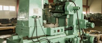
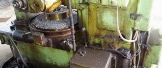
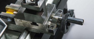
3B642 General view of the sharpening machine
Photo of universal sharpening machine 3B642
Photo of universal sharpening machine 3B642
Photo of universal sharpening machine 3B642
Photo of universal sharpening machine 3B642
Machine 3E642. Universal sharpening. Manual. Electrical equipment
This instruction manual for the “Universal sharpening machine 3E642” contains information necessary both for the maintenance personnel of this machine and for the employee directly involved in working on this machine. This manual is an electronic version in PDF format of the original paper version. This documentation contains the Manual (instructions) for operating the electrical equipment of the 3E642 universal sharpening machine.
CONTENT
Characteristics of electrical equipment Power system Initial start-up Description of operation
- Operation of the electrical automation circuit of the machine
- Operation of the skid reverse board
Interlocks Alarm system Protection Instructions for safety measures Possible malfunctions and methods for eliminating them
download the operating manual for the electrical equipment of the universal sharpening machine 3E642 in good quality from the link below.
Operating manual for electrical equipment of the universal sharpening machine 3E642. Download for free.
Location of components of the sharpening machine 3B642
Location of components of the sharpening machine 3B642
Specification of components of the sharpening machine 3B642
- I. Unit 24. Lifting mechanism
- II. Unit P. Accessories
- III. Unit 60. Cooling
- IV. Unit 40. Grinding head
- V. Unit 30. Caliper
- VI. Unit 91. Mandrels
- VII. Unit 31. Planetary gearbox
- VIII. Unit 10. Bed
- IX. Unit 92. Housings
- X. Node 20. Column
- XI. Unit 80. Electrical equipment
- XII. Unit 21. Gearbox
Unit 90. Accessories (not shown in the figure)
Unit 93. Fence (not shown in the figure). Universal devices, which serve to expand the range of work performed on the machine, are supplied with the machine and are included in the kit and price of the machine, and special devices are supplied upon request of consumers for a special fee.
The universal sharpening machine is designed for sharpening the main types of cutting tools: cutters, milling cutters, countersinks, etc. The machine is equipped with various devices that allow you to install and secure the tool being sharpened. In addition to tool sharpening, the machine can perform external, internal and surface grinding.
The main components of the 3B642 machine: a bed, a table with a support group and a grinding head with a spindle on which grinding wheels are mounted. There are devices on the table. The transverse and longitudinal movement of the table is carried out respectively by flywheels, and the raising and lowering of the grinding head is carried out by a flywheel.
Album of drawings of spare and wearing parts of the 3E642 machine. Universal sharpening.
This manual “Universal sharpening machine 3E642. Album of drawings of spare and wearing parts. » contains information necessary for the operating personnel of this machine. This manual is an electronic version in PDF format of the original paper version.
download the album of spare parts for the universal sharpening machine 3E642 in good quality using the link below.
Album of spare parts for the 3E642 universal sharpening machine. Download for free.
3В642 Location of sharpening machine controls
Location of controls for sharpening machine 3B642
3В642 List of sharpening machine controls
- Vertical feed handwheel
- Slow vertical feed button
- Window cover for access to the spindle motor
- Spindle motor stop button
- Slow vertical feed switch handle
- Spindle motor start button
- Fine cross feed handwheel
- Screw for securing the table against rotation
- Table rotation screw
- Left table support
- Cooling tap
- Grinding Wheel Guard Clamps
- Right table support
- Button for turning on slow longitudinal feed of the table manually
- Handwheel for slow longitudinal table feed manually
- Plug socket for connecting the electric motor of the vacuum cleaner
- Cooling tank niche cover
- Input switch (automatic)
- Electrical cabinet cover lock
- "General stop" button
- Cross feed handwheels
- Handle for securing the grinding head against vertical movement
- Grinding head rotation handle
- Nut securing the grinding head against rotation
- Spindle rotation lock button
- Light switch
- Manual table longitudinal feed handwheel
- Nuts for securing the table against rotation
- Jog cross feed lever
- Signal lamp
- Spindle reverse
- Cooling and vacuum cleaner switch
- Spindle motor speed switch
- Plug socket for connecting electric motors of devices
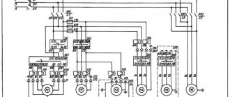
3B642 Kinematic diagram of the sharpening machine
Kinematic diagram of the sharpening machine 3V642
The main movement - rotation of the spindle with grinding wheels 1 and 2 - is carried out from a two-speed electric motor 3 through belt drives 4-5 or 6-7 and then through gear 8-9 to spindle 11.
The periphery of the cylindrical circle 2 is used to grind the surfaces of the rotating bodies, which are installed in the centers of the device on the machine table, and the cup wheel 1 is used to grind the flat surfaces of the tool, for example, the thread of a tap along the front plane.
The electric motor , together with the bracket on which it is mounted and with the pulley 8, can be lowered down using a screw 10, tensioning the grinding head belt.
The grinding head with grinding wheels 1 and 2 (Fig. 78, a) is mounted on the top of the vertical column 11 and can be rotated with it around a vertical axis (Fig. 78, b). In addition to turning, the column can move up or down using flywheels 12 or 13. From flywheel 12, movement can be transmitted directly to shaft I if clutch 45 is turned on with button 14 (fast movement) or through a planetary mechanism with gears 15-18 and then through worm gear 19-20 to a rack and pinion pair with a rack wheel 21 and a rack 22 mounted on a column (slow movement).
If the column moves with the help of flywheel 13, then the movement goes through the conical pair 23-24 and further along the same chain.
The table with support group consists of three parts. On the upper rotating part 25, the tool to be sharpened is installed in the appropriate fixtures. The upper part of the table rotates relative to the middle part 26 to sharpen the conical surfaces of the tool. The middle part of the table 26 has manual longitudinal movement on roller guides of the lower part of the table 27. This movement is carried out by flywheels 28 or 29 with rack and pinion gears 30, or by a handle 31 on the body (lead) of the planetary gear. In the latter case, by pressing the button 32, the rack wheel 33 associated with the planetary mechanism is turned on, and the wheels 30 associated with the flywheels 28 and 29 are disconnected from the rack 34, while the table receives a slow transverse feed from the planetary mechanism with wheels 35-38.
The lower part of the table 27, together with the middle and upper parts, is moved in the transverse direction using a lead screw 39 and a nut fixed to the frame. Fine (slow) transverse feed is carried out by rotating flywheels 40 or 41, which turn the lead screw 39 through gears 42-43.
The ratchet mechanism 44, which is driven by a special handle, through the same gear 42-43 communicates to the lead screw, and therefore to the table, a periodic slow motion. The fine (slow) table feed allows the tool to be sharpened to be carefully brought to the grinding wheel.
Machine accessories significantly expand the range of use of the machine. These include: a headstock with indexing disks, a tailstock, a universal sharpening head, a universal rotary vice, a device for dressing wheels, a device for sharpening cutters with backed teeth, a device for sharpening drills, a stop for sharpening cutters with screw teeth and some others.
Technical data and characteristics of the 3B642 machine
| Parameter name | 3В642 | 3B642 |
| Main settings | ||
| Accuracy class according to GOST 8-82 | P | P |
| The largest dimensions of the processed products in the centers (length x diameter), mm | 630 x 250 | 630 x 250 |
| Distance between the centers of the universal and tailstock, mm | 550 | 550 |
| Distance between the axis of the grinding wheel and the line of centers in the horizontal plane, mm | 70..300 | 70..300 |
| Distance between the axis of the grinding wheel and the line of centers in the vertical plane, mm | 65..185 | 65..185 |
| Machine work table | ||
| Dimensions of the working surface of the table according to GOST 6569-75 (length x width), mm | 900 x 140 | 900 x 140 |
| Maximum longitudinal/transverse manual movement of the table, mm | 450/ 230 | 450/ 230 |
| Longitudinal/transverse movement of the table by one division of the dial, mm | 0,1/ 0,01 | 0,1/ 0,01 |
| Transverse table movement by one fine feed division, mm | 0,0025 | 0,0025 |
| Table rotation angle in the horizontal plane, degrees | 90 | 90 |
| Table movement speed from hydraulic drive, m/min | — | 0,2..8 |
| Grinding head | ||
| Maximum vertical movement of the headstock, mm | 250 | 250 |
| Price for dividing the feed dial for vertical movement of the table, mm | 0,005 | 0,005 |
| Headstock rotation angle in the horizontal plane, degrees | 350 | 350 |
| Grinding head | ||
| Grinding wheel speed with stepwise regulation, rpm | 2240, 3150, 4500, 6300 | 1300..6500 b/s |
| The end of the grinding spindle according to GOST 2324-77 version 2 | Morse 3 | Morse 3 |
| The largest diameter of the installed grinding wheel, mm | 200 | 200 |
| The largest diameter of the installed grinding wheel of other types, mm | 150 | 150 |
| Universal head | ||
| Spindles inner taper size | Morse 5 | Morse 5 |
| Angle of rotation in horizontal and vertical areas, degrees | 360 | 360 |
| Electrical equipment and machine drive | ||
| Number of electric motors on the machine | 4 | 5 |
| Electric motor for spindle drive of grinding wheels, kW | 1,5/ 1,1 | 2,5 |
| Product drive electric motor, kW | 0,25 | 0,25 |
| Hydraulic drive electric motor, kW | — | |
| Cooling pump electric motor, kW | 0,125 | 0,125 |
| Vacuum cleaner electric motor, kW | 0,125 | 0,125 |
| Total installed power of all electric motors, kW | 1,795 | |
| type of supply current | 50Hz, 380/220V | 50Hz, 380/220V |
| Dimensions and weight of the machine | ||
| Machine dimensions, mm | 2050 x 1820 x 1550 | 2050 x 1820 x 1550 |
| Machine weight, kg | 1250 | 1280 |
- Universal sharpening machine 3B642. Operating instructions 3В642.000 РЭ, 1978
- Dibner L.G., Tsofin E.E. Sharpening machines and semi-automatic machines, 1978
- Demyanovsky K.I., Dunaev V.D. Sharpening wood cutting tools, 1965
- Kudryashov A.A. Tool production machines, 1968
- Lisova A.I. Design, adjustment and operation of metal-cutting machines, 1971
- Menitsky I.D. Universal sharpening machines, 1968
- Paley M. M. Technology of production of metal-cutting tools, 1982
- Rozhkov D.S. Design, setup and operation of equipment for sharpening wood-cutting tools, 1978
Bibliography:
Related Links. Additional Information
- Classification and main characteristics of the grinding group
- Repair, restoration and modernization of grinding machines: the American approach
- Cylindrical grinding. Processing on cylindrical grinding machines. Grinding Methods
- Setting up a cylindrical grinding machine when installing parts in centers
- CNC grinding machines
- Marking of grinding wheels
- Testing and checking metal-cutting machines for accuracy
- Grinding machines. Market of grinding machines in Russia
- Directory of grinding machine manufacturers
- Directory of factories producing metal-cutting machines
- Directory of surface grinding machines
Home About the company News Articles Price list Contacts Reference information Interesting video KPO woodworking machines Manufacturers