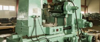
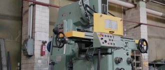
Information about the manufacturer of the semi-automatic vertical gear hobbing machine 5E32
Manufacturer of the vertical gear hobbing semi-automatic machine 5E32 Egoryevsky Machine Tool Plant Komsomolets, SZK , founded in 1930.
During its existence, the plant has produced over 60 models: gear hobbing, gear shaping, gear grinding, gear rounding and other gear processing machines.
Products of the Yegoryevsk Machine Tool Plant Komsomolets, SZK
- 5A12
- semi-automatic vertical gear shaping machine Ø 208 - 5A140P
- semi-automatic vertical gear shaping machine Ø 500 - 5B150
– semi-automatic vertical gear shaping machine Ø 800 - 5B833
- vertical gear grinding machine for cylindrical gears Ø 200 - 5D32
- vertical gear hobbing machine for cylindrical gears Ø 800 - 5E32
- vertical gear hobbing machine for cylindrical gears Ø 800 - 5K32
- vertical gear hobbing machine for cylindrical gears Ø 800 - 5K32A, 5K324A
- vertical gear hobbing machine for cylindrical gears Ø 800 - 5K324
- vertical gear hobbing machine for cylindrical gears Ø 500 - 5K328A
- vertical gear hobbing machine for cylindrical gears Ø 1250 - 53A11
- vertical gear hobbing machine for cylindrical gears Ø 1250 - 53A50
- vertical gear hobbing machine for cylindrical gears Ø 500 - 53A80
- vertical gear hobbing machine for cylindrical gears Ø 800 - 514
— semi-automatic vertical gear shaping machine Ø 500 - 532
— vertical gear hobbing machine for cylindrical gears Ø 750 - 5310
— vertical gear hobbing machine for cylindrical gears Ø 200
5E32 Semi-automatic vertical gear hobbing machine. Purpose and scope
5E32 machine is an improved model of the 5D32
. The 5E32 machine has a different automatic shutdown of the radial feed of the rack. In addition, the machine mechanism quickly brings the cutter to the workpiece being processed, switches to the working stroke, and after cutting the teeth, moves the caliper to its original position. The cutter is moved to the cutting depth, as on a 5D32 machine, by moving the support stand.
5E32 gear hobbing machine was replaced by a more advanced model of the K series 5K32
.
The gear hobbing machine model 5E32 is universal and is designed for milling cylindrical spur and helical gears of medium size with hob cutters, as well as worm wheels using the radial method in conditions of single, small and medium-scale production.
This 5E32 can be used for gear cutting using up and down milling methods. The machine operates in a closed semi-automatic cycle, has a mechanism for moving the cutter, which increases the durability and service life of the cutters; allows you to work at increased cutting speeds and feeds.
Operating principle and design features of the machine
To ensure uniform wear of the cutter teeth along the entire length, it has axial movement. Moving is done by pressing a button; When the button is released, the movement of the cutter stops.
Cutting of gears is carried out by the method of running in the cutter and the workpiece using the methods of “downstream” and “counter” gear hobbing with diagonal and normal feeds.
When gear hobbing with a diagonal feed, the cutter moves along the tooth being cut and at the same time along its own axis, which significantly increases its durability.
5E32 machine provides the possibility of radial cutting of the cutter into the workpiece, which reduces machine processing time.
Worm wheels can be cut with radial and axial feed of the cutter. In the latter case, a broaching support is required, which is supplied with the machine and upon special order.
The machine is designed to work with high-speed steel hobs. Machining of cylindrical wheels can be carried out using the method of “counter” (vertical feed of the cutter from top to bottom) and “climbing” milling (vertical feed of the cutter from bottom to top).
With the “upstream” method, an increase in cutting speed by 20-25% is allowed compared to the “counter” method. This results in better tooth surface cleanliness.
The cutting of gears is carried out using the method of running in a hob cutter and the workpiece being processed. During operation of the machine, a simultaneous rotational movement of the hob cutter (cutting movement) and its vertical movement (feed movement) are carried out. The workpiece, mounted on a mandrel or stand mounted on the machine table, rotates during operation in coordination with the cutter.
Gears can be cut on the machine in one or more passes by changing the cutting depth setting accordingly.
5E32 machine operates in a closed semi-automatic cycle and an adjustment cycle. A special device allows you to produce:
- automatic machine stop at the end of cutting
- quick feed of the caliper slide and stand, necessary during setup
- rapid movement of the cutter to its original position
5E32 machine is manufactured in accordance with accuracy standards according to GOST 659-53.
Gear hobbing machines operating using the rounding (running in) method
Rice.
1. Gear hobbing machines using the rounding method Fig. 2. Schematic diagram of setting up a gear hobbing machine
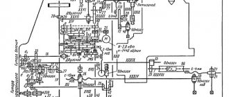
Rice. 3. Block diagram of a gear hobbing machine
Gear hobbing machines operating using the rounding (running in) method are designed for processing cylindrical wheels with straight and oblique teeth, as well as worm wheels (see Fig. 3).
When cutting teeth, the rotation of the cutter and the workpiece must be coordinated with each other. To ensure this condition, the machine has a special circuit, the configuration diagram of which is shown in Fig. 2. If the wheel has z teeth and makes pk revolutions, and the cutter makes nf revolutions during this time, then the gear ratio is ix between the number of revolutions of the wheel and the cutter.
Let's consider the shaping movements of the machine to form the profile of the teeth, for which we turn to the structural diagram of the machine (Fig. 3). When cutting a spur gear, it is necessary to carry out the main rotational movement of cutter B1. rotation of the workpiece B2, controlled by the tuning element iv, coordinated with the rotation of the cutter Bx; movement of the support with the cutter parallel to the axis of the table P, adjusted by the i3 organ. The support can move either from top to bottom or from bottom to top. When the caliper moves from top to bottom, counter milling is carried out. In this case, when the cutter rotates, the teeth move towards the metal layer being cut. When the support moves from bottom to top, down milling occurs. In this case, the cutter teeth move in parallel with the layer of metal being cut. When down milling, it is allowed to increase the cutting speed by 20-25% compared to the down milling method.
When cutting helical gears, to the form-building movements discussed above, a movement is added to form a helical line (differential chain). This movement consists of rotation of the workpiece B3 and translational movement of the cutter P. Consequently, one executive link - the machine table - must have two rotations B2 and B3 with independent speeds, which is possible with a summing mechanism.
Processing methods
The production of worm products is carried out by other methods. For processing, 2 types of plunge are used - radial and tangential.
Radial processing method - carried out using a radial moving screw. During operation, one movement is performed (FU - B1B2), which divides and forms the surface of the teeth.
For radial processing, one plunge movement is used (BP - P7).
The tangential processing method is used much less frequently than the radial method, but no worse.
The main working mechanisms are a tangential screw and a modular hob cutter with a fence-shaped cone.
To form teeth and dividing operations, the same movement is used as in the first method (FU - B1B2). But the side surfaces of the teeth are formed 2 times, the first has already been discussed, and the second occurs simultaneously with the cutting of the cutter into the workpiece.
For tangential cutting of the cutter, namely the conical part, the movement ФS2 – П5B6 is carried out.
Location of the components of the semi-automatic gear hobbing machine 5E32
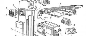
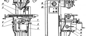
Location of the main components of the 5e32 gear hobbing machine
Location of the main components of the 5e32 gear hobbing machine
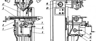
The 5E32 machine (Fig. 51) consists of the following main components:
- bed 4,
- caliper strut 19,
- sled 10,
- caliper 11,
- table 7,
- rear pillar 9
- cross member 14.
The bed 4 is the base of the machine; it has guides for the movement of the rack 19 and ring guides for rotating the table 7. Inside the frame there are electric motors E1 for the main movement (see Fig. 53), E2 - for rapid movements of the support, support stand and spindle with a cutter, EZ - for the pump (not shown in the diagram) supplying coolant. The EZ electric motor turns on only when E1 is turned on, i.e., coolant is supplied when the cutter rotates.
The slide 10 is designed to move the caliper 11 up and down quickly or slowly depending on the idle or working stroke.
When processing worm wheels, the slide, after proper installation, is secured with bolts 21 on the guides of the rack 19.
The support 11 can be rotated and mounted on the slide at the required angle of the cutter to the workpiece. To measure the angle of rotation of the caliper, it has a circular scale in degrees, and on the slide there is a vernier with a division value of 6 minutes.
A flywheel 25 is mounted on the cutter spindle, which serves to increase the smoothness of rotation of the cutter during the cutting process. There is also an E4 electric motor with a cutter movement mechanism and an oil level indicator 24.
Under the covers there is a differential guitar 2, a speed guitar 1, a gear of divisions and hydraulic control, a feed guitar 23. Under covers 6 there are racks for storing replacement gears, under cover 20 there is a cabinet with electrical equipment.
The support stand 19 can move along the frame guides and be secured with nuts 3 and 13 in any position. The movement of the stand is limited by a movable stop 5.
Inside the rack are the main movement and feed mechanisms and the caliper hydraulic counterweight cylinder. On the rear wall of the rack there is an electrical equipment control panel, on the cover 20 of which there are switches for the electrical power supply and the coolant pump motor. On the slide in the grooves there are adjustable cams 16, 17, 18, which, acting on the track switches PV1, PV2 and PVZ, control the movement in the rack.
The contact surfaces of the cams and switches are located so that cam 16 acts only on switch PV3, and cam 18 on switch PV2 and cam 17 on switch PV1, freely passing by the other switches. Cams 16, 17, 18 are installed depending on the size of the idle and working strokes of the caliper.
Behind the slide there are cams that act on a switch that turns off the movement of the caliper in extreme positions. Handle 22 is used to turn on and off the working feed of the caliper.
Table 7 imparts rotation to the workpiece, usually mounted on mandrel 8.
The rear post 9 is motionless relative to the table. The bracket 15 can move along its internal guides. A bushing with an internal cone is fixed in the bracket, precisely centering the mandrel 8. Instead of the bushing, a center can be installed that supports the upper end of the installed workpiece. When the handle 12 moves toward itself, the bracket 15 is fixed in any position, and the movement of the handle toward itself serves to rotate the rack and pinion gear, which rolls along a rack attached to the rack 9 and moves the bracket 15.
The cross member 14 serves to increase the rigidity of the machine, minimizing deformation of the racks and vibration.
Introduction
The gear hobbing machine is designed to create cylindrical products.
If the equipment contains a vertical and radial lead screw, the apparatus becomes suitable for creating worm wheels. For this purpose, modular hob cutters are used. The principle of creating cylindrical and worm products is based on rolling and copying the workpiece. The type of processing depends on the equipment of the mobile propeller.
In addition, machines differ in the location of the workpiece axis - vertical and horizontal. The machines are divided into two types, but are similar in design.
Vertical machines consist of a bed and a tool rack. They have a movable stand or a mobile table that moves in a radial direction. There is also an additional movable table that moves vertically.
Horizontal machines are designed to work with products of increased complexity. The movable stand moves horizontally. Horizontal machines for cutting small products have a special movable table that is used to support the product.
Below you will find detailed information about the operation of the machines.
Location of controls for semi-automatic gear hobbing machine 5E32
Location of controls for gear hobbing machine 5e32
List of machine controls 5E32
- stop for automatically switching off the caliper feed
- automatic cycle warning light
- main motor switch button
- automatic cycle adjustment switch
- button for turning on the axial movement of the cutter
- button that stops the main motor
- button for turning on the fast movement of the caliper up
- button for switching the axial movement of the cutter
- Button for switching off the fast movement of the caliper down
- square for manual movement of the caliper slide
- radial feed mechanism activation handle
- square for manual movement of the caliper stand
- handle for turning on the vertical feed of the caliper
- lever for turning on and off the working feed
Safety precautions
Safety precautions have a number of requirements that must be met. Items are divided into several lists.
Requirements:
- Allow only trained people to work.
- Perform only assigned tasks.
- The worker must wear a special uniform.
- Slippery floors are equipped with a special coating.
Requirements before starting work:
- After accepting a machine from another worker, ensure that the work area is clean.
- Availability of good lighting.
- A check of the machine's functionality is required. Also make sure you have the required amount of lubricant.
Requirements during operation:
- Fasten the part correctly and as securely as possible.
- Use special tools for fixing and processing.
- Use lifting equipment to install and remove large parts.
- Do not put your hands in dangerous places when milling.
Semi-automatic operating cycle of gear hobbing machine 5E32
The 5E32 machine has a semi-automatic operating cycle, carried out through a hydraulic mechanism (see Fig. 13 and 24) in conjunction with electrical devices.
When starting the machine, turn on the high speed motor and move the support to the product. At this time, the main movement motor 1D is turned off and the G12-11-A type vane pump does not work, which means there is no oil in the hydraulic system.
After the support is brought to the product using the stop and limit switch 1VK, the high speed motor ZD is turned off, the main movement motor 1D and the vane pump G12-11-A are simultaneously turned on - the working feed is in progress. The EM electromagnet is turned off at this time.
The spool (part No. E32-21-307) is in the upper position under the action of the spring A25 x 1.6 x 70 DK820, oil from the vane pump enters under pressure into the other cavity of the spool, overcomes the spring holding the piston (part No. E32-21- 303), a hole opens and oil enters the hydraulic system; The oil drain from the upper cavity is closed at this time.
At the end of the working stroke, the stop presses the limit switch 5VK, which turns off the main movement motor 1D, and at the same time the vane pump G12-11-A is turned off.
When the pressure in the system drops, along with the main movement motor 1D turning off, the EM electromagnet turns on, which pushes the spool (part No. E32-21-307) down, closes the oil supply and opens the drain hole from the upper cavity. From the drop in pressure under the action of the spring A38 x 4 x 85 DK820, the piston E32-21-303 moves upward and turns the lever (part No. E32-21-073) mounted on the roller.
When turning the stop, the limit switch ZVK is pressed, turning on the high speed motor ZD, and the caliper is quickly retracted to the initial position. At this time, the drain hole is open and oil from the hydraulic system is drained into the reservoir.
After the end of the high speed, when you press the stop on the limit switch 6VK, the high speed motor 3D is turned off, the axial movement motor of the milling cutter 4D is turned on, the operating time of which is regulated using a time relay RV. After the axial movement of the cutter, the machine’s operating cycle ends.
This order of the work process applies to both “climbing” milling and “counter” milling.
Main settings
Let's take a closer look at the technical characteristics of the equipment.
As already mentioned, the equipment is intended for creating worm and cylindrical products, and is also divided into 2 types - vertical and horizontal.
The equipment has straight and helical gear teeth. The profile of a part can be formed in different ways, depending on the type of processing. The tooth shape differs only in length, determined by touch.
The structure of equipment with the copying method is simple and includes three groups:
- FV(B1).
- FS(P2).
- Division D(B3).
Equipment that is based on the rolling-in method is also divided into groups:
- FV (B1 B2) – dental profile.
- FS(P3) – spur profile.
- FS (P3 B4) – oblique profile.
When copying workpieces, the cutting parts of the tools must match the shape of the gear. After cutting the cavities, the head rotates, 1 cavity - 1 rotation of the teeth. For rotation, a division method is used, which is carried out by a special internal mechanism.
Haas (Formula 1 team)
When the material is rolled in, the gears begin to move continuously. The movement is carried out by the main processing tool. The type of rolling depends on the type of movement - hot or cold.
Operation of the electrical circuit of the 5E32 gear hobbing machine
The machine is equipped with four three-phase squirrel-cage electric motors for voltage 220/380 V:
- main drive electric motor type A-51/4 with a power of 4.5 kW, 1440 rpm (1D)
- electric motor of a cooling pump type PA-45 with a power of 0.15 kW, 2840 rpm (2D)
- high-speed electric motor type AO-32/4 with a power of 1.0 kW, 1410 rpm (ZD)
- electric motor for moving the cutter type AOL-12/4 with a power of 0.18 kW, 1400 rpm (4D)
Before starting work at the headquarters, the LV line switch is turned on, thereby supplying voltage to the starting equipment. The PU switch is set to the “adjustment”, “passing” or “counter” position.
If cooling is necessary, the VDO switch is turned on. The electric motor of the cooling pump is turned on simultaneously with the main drive motor using a 1K motor.
Obtaining relief surfaces
Climbing with a milling cutter tilted approximately 10° in two directions ensures good surface quality and reliable performance. A ball nose or radius cutter will produce a surface with a specific ridge height, h, depending on:
- cutting width, ae
- feed per tooth, fz
Other important factors are the depth of cut, ap, which affects the cutting forces, and the tool runout indicator (TIR) reading. For optimal results:
- Use a high-precision hydroplastic chuck with a Coromant Capto connection
- Reduce tool overhang to a minimum
Roughing and semi-finishing
If the feed per tooth is much less than the width and depth of cut, then the resulting surface will have a much smaller height of ridges (transitions) in the feed direction.
Finishing and processing
The aim should be to achieve a smooth, symmetrical surface texture in all directions, which can then be easily polished regardless of the polishing method chosen.
This is achieved at fz ≈ ae.
For optimal surface texture, always use a two-flute angled cutter when finishing.
Semi-finishing with fz much smaller than ae Finishing with an inclined cutter at fz = ae
Technical characteristics of gear hobbing machine 5E32
| Parameter name | 532 | 5d32 | 5e32 | 5k32 |
| Basic machine parameters | ||||
| Largest modulus of a cut wheel for steel, mm | 6 | 2..6 | 2..6 | 10 |
| The largest diameter of cut cylindrical spur wheels (0°), mm | 750 | 800 | 800 | 800 |
| The largest diameter of cut cylindrical helical wheels (30°), mm | 500 | 500 | 500 | 500 |
| The largest diameter of cut cylindrical helical wheels (45°), mm | 350 | |||
| The largest diameter of cut cylindrical helical wheels (60°), mm | 190 | 190 | 120..250 | |
| The largest diameter of worm cut wheels, mm | 800 | |||
| Maximum length of the crown of cut cylindrical spur wheels (0°), mm | 250 | 350 | ||
| Maximum length of the crown of cut cylindrical helical wheels (30°), mm | 200 | |||
| Maximum length of the crown of cut cylindrical helical wheels (45°), mm | 150 | |||
| Maximum length of the crown of cut cylindrical helical wheels (60°), mm | 130 | |||
| Minimum number of teeth cut | 12 | |||
| Distance between the axes of the table and the cutter, mm | 30..480 | 30..500 | 30..480 | 80..500 |
| Distance from the table plane to the cutter axis, mm | 165..415 | 200..510 | 190..525 | 210..570 |
| Distance from the spindle axis to the support guides, mm | 218 | 220 | 319 | |
| Table | ||||
| Table diameter, mm | 580 | 475 | 475 | 670 |
| Maximum table movement, mm | 425 | — | — | 500 |
| Cone in the table spindle, mm | Morse 5 | |||
| Accelerated table movement, mm/min | — | — | — | 170 |
| Manual table movement per dial division, mm | 0,1 | — | — | 0,5 |
| Manual movement of the table per one revolution of the dial, mm | 5 | — | — | |
| Caliper strut | ||||
| Maximum movement of the support strut, mm | 470 | 450 | — | |
| Rapid movement of the support strut, mm/min | — | 50 | 230 | — |
| Movement of the stand by one division of the dial, mm | — | 0,05 | 0,02 | — |
| Movement of the rack per one revolution of the dial, mm | — | 4,0 | 4,0 | — |
| Overload lock | There is | There is | — | |
| Caliper | ||||
| Maximum movement of the caliper, mm | 250 | 335 | 360 | |
| Accelerated movement of the caliper carriage, mm/min | 220 | 550 | ||
| The largest diameter of the cutting tool - cutters, mm | 120 | 120 | 150 | 200 |
| Minimum length of cutting tool (cutter), mm | 130 | 130 | 200 | |
| Diameters of milling mandrels, mm | 22, 27, 32 | 32; 40 | ||
| Accelerated spindle movement along the axis, mm/min | 130 | |||
| Maximum caliper rotation angle, degrees | 360° | |||
| Maximum angle of inclination of the teeth of the cut wheel, degrees | ±60° | ±60° | ||
| Rotate the caliper by one division of the ruler scale, degrees | 1° | 1° | ||
| Rotate the caliper by one division of the vernier scale, min | 6` | 1` | ||
| Spindle Taper Bore | Morse 4 | Morse 5 | Morse 5 | |
| Maximum axial movement of the cutter, mm | 80 | |||
| Machine mechanics | ||||
| Cutter speed limits, rpm | 47, 58, 72, 87, 100, 122, 150, 188 | 47,5..192 | 53,5..250 | 5..310 |
| Number of cutter speed steps | 8 | 8 | 9 | |
| Limits of vertical (longitudinal) cutter feeds, mm/rev | 0.25..4 (12 steps) | 0,5..3 | 0,8..5,0 | |
| Limits of radial feeds of the movable rack, mm/rev | 0,1..1,0 | 0,3..1,7 | ||
| Limits of radial feeds of the movable table, mm/rev | 0.105..1.68 (12 steps) | — | — | |
| Limits of tangential (axial) cutter feeds, mm/rev | 0,17..3,7 | |||
| Number of feed stages | 7 | |||
| Drive and electrical equipment of the machine | ||||
| Main drive electric motor, kW (rpm) | 3,2 (1440) | 2,8 | 4,5 | 7,5 |
| Electric motor for rapid movement of the caliper, kW (rpm) | 1,0 (1425) | 1,0 | 3,0 | |
| Electric motor driving the axial movement of the cutter, kW (rpm) | — | 0,18 | 0,4 | |
| Hydraulic pump drive electric motor, kW (rpm) | — | — | 1,1 | |
| Cooling pump electric motor, kW (rpm) | 0,25 (2800) | 0,15 | 0,15 | 0,15 |
| Overall dimensions and weight of the machine | ||||
| Overall dimensions of the machine (length x width x height), mm | 1885 x 1158 x 1950 | 2395 x 1210 x 1975 | 2390 x 1340 x 2080 | 2550 x 1510 x 2000 |
| Weight of the machine with electrical equipment and cooling, kg | 2500 | 3660 | 4000 | 7200 |
- Universal gear hobbing machine 5E32. Use and Care Manual, 1960
- Acherkan N.S. Metal-cutting machines, Volume 1, 1965.
- Galperin E.I. Setting up gear cutting machines, 1960, p. 66
- Kozlov D.N. Gear cutting work, 1971.
- Kucher A.M. , Kivatitsky M.M., Pokrovsky A.A., Metal-cutting machines (Album of general types, kinematic diagrams and components), 1972.
- Loskutov V.V. , Nichkov A.G. Gear processing machines, 1978.
- Malakhov Y.A. Gear-processing and thread-milling machines and their adjustment, 1972.
- Milshtein M.Z. Cutting gears, 1972.
- Ovumyan G.G. , Adam A.I. Gearcutter's Handbook, 1983.
- Ptitsin G.A. , Kokichev V.N. Gear cutting machines, 1957.
- Shavlyuga N.I. Calculation and examples of adjustments for gear hobbing and gear shaping machines, 1978.
- Guiding material for designers designing technological equipment. Basic data and seats of metal-cutting machines. NIIMASH, 1968.
List of literature on tooth processing
Related Links. Additional Information
- Classification and main characteristics of gear-processing machines
- How to buy a machine for production
- Gear hobbing machines for cylindrical wheels
- Counter milling. Climb milling when cutting gears on a gear hobbing machine
- Bevel gear. Terms and Definitions
- Testing and checking metal-cutting machines for accuracy
- Manufacturers of milling machines in Russia
- Manufacturers of metal-cutting machines in Russia
- Directory of gear processing machines
Home About the company News Articles Price list Contacts Reference information Interesting video KPO woodworking machines Manufacturers
