Information about the manufacturer of threading machine 5993
The manufacturer of the thread-cutting machine 5993 is the Chita Machine Tool Plant , founded in 1957.
The plant produced the following equipment:
- universal sharpening machines model 3640, 3B641
- honing machine model 3833M
- diamond sharpening machine model 3B632V
- semi-automatic thread-cutting machines 5D07 (1960-1982), 5991, 5992, 5993, 5994 (1977), 5A993, ChS 5A100S
- magnetic plates, magnetic cartridges, sine plates and other magnetic technological equipment on permanent magnets - about 46 types in total.
Machine tools produced by the Chita Machine Tool Plant
- 3B641
- universal sharpening machine Ø 250 x 650 - 5D07
thread-cutting machine for cutting external cylindrical threads Ø 39 x 320 - 5993
thread-cutting machine for cutting external cylindrical threads Ø 42 x 280
Buy thread cutting machines
Purchasing a pipe threading machine is a responsible undertaking that requires taking into account all the features of the equipment and the production process. Before placing an order in our online store, consult with a TBS specialist by calling the hotline (toll-free in Russia). You can also use online chat.
TBS company warehouses with a full range of equipment for pipe processing are located in Moscow, St. Petersburg and Novosibirsk. In these cities you can order courier delivery of goods. Since the price of any thread-cutting machine exceeds 10,000 rubles, according to our rules, we will deliver the equipment free of charge within the city. To representatives of other regions, the machine and components will be sent by a trusted transport company.
Instructions for sharpening and installing threading dies
Sharpening and measuring of dies for self-opening screw-cutting heads of standard sizes 2651-0021 (1KA-25); 2651-0022 (2KA-30); 2651-0024 (ZKA-40); 2651-0026 (4KA-70) and 2651-0028 (5KA-70) in accordance with GOST 21760-76 should be produced in accordance with the operating instructions for these heads attached to the machine.
Sharpening of flat dies for thread-cutting heads 1T, 2T, 3T can be done according to GOST 2287-61 in two forms: form I and form II in a sharpening device, fig. 13 (unit 5993.98.000), available for an additional fee. In this case, sharpening form 1 is recommended.
The sharpening geometry is shown in Fig. 28. Recommended sharpening angles depending on the material being processed are shown in the table in the figure. Setting the extension of the dies, cutting modes and the used cutting fluid are given in the operating instructions for 1T, 2T and 3T threading heads.
Metric and inch threads
There are a huge number of threads in the world, but the most common are metric and imperial.
Inch is much older than metric. It was developed in Great Britain at the end of the 18th century during the Industrial Revolution.
Metric was developed in France, a historical competitor of Great Britain. It was much simpler and more convenient, since integer numbers were taken as a basis, as opposed to inch numbers.
In Russia, metric is used in mechanical engineering, and inch is cut on pipes, adapters and fittings for water and gas supply.
Metric threads benefit from greater variability. In addition to the nominal value (diameter), the pitch is also indicated. Thread pitch is the distance between two profile points of the same name.
A thread profile is a regular (equilateral) triangle; in such a triangle, all angles have a value of 60 degrees. The profile height is 0.86 thread pitch.
Thread cutting machine and everything about it
A thread cutting machine is equipment that cuts conical and cylindrical workpieces. It also cuts threads on pipes (gas, water, etc.) and the machines can also be used as equipment for the production of bolts. Thanks to the versatility of this machine, its range of applications expands from large production facilities to small repair shops.
Design and operating principle of pipe threading machine
The device itself is similar in type to a vertical drilling machine. A special tool is attached to the spindle - a tap; it is this that, in accordance with the set speed and rotation frequency, moves down towards the firmly and tightly fixed pipes. When cutting long pipes, a stand is used that is adjustable in length and height. Depending on the type, a drilling and tapping machine may have a horizontal or vertical placement of the operating tool. More often, vertical equipment is used, with a tap acting as a cutter. But horizontal machines are used for cutting threads of various types of pipes. External threads are made using thread cutters and round dies. But internal work is carried out using special cutters and taps.
Types of threads that can be made using a thread cutting machine:
- Metric and inch threads on pipes;
- Conical, trapezoidal and cylindrical.
When using additional tools, it becomes possible to make tilts and set various shapes.
Thread cutting machine, its types
The presented equipment can be divided into three groups:
- Manual machines;
- Electrical machines;
- Automatic machines.
The type of such equipment is selected based on the planned volume of thread cutting. One of the most important advantages of using a manual machine is its mobility. Such equipment is not large in volume and weight, due to this it can be easily moved from one place to another. To work on it, no special skills or knowledge are required. But the main drawback is that threading pipes with a diameter of more than 50 mm is not possible. Often such machines are used, so to speak, in garage conditions and small workshops.
The electric threading machine has a large weight, volume and complex structure. But unlike manual equipment, they are used in production, they are more reliable and allow you to work with pipes with a diameter of more than 50 mm. Compact electric models weigh around 60 kg, but their functions are limited. More powerful models can weigh up to 200 kg.
Thread cutting on automatic machines occurs without human intervention. This machine is very large and is used in factories for the continuous production of pipes.
Threading machines for pipes are the main equipment that no serious enterprise specializing in threading can do without.
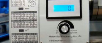
Technical data and characteristics of the 5993 threading machine
| Parameter name | 5993 | 5D07 |
| Main settings | ||
| Accuracy class according to GOST 8-82 | N | N |
| Productivity when cutting short threads, pcs/h | 500 | |
| Diameter of metric thread cutting, mm | 12..42 | 10..39 |
| Steps of cut metric threads, mm | 1,75..4,5 | |
| Thread cutting diameter inch, mm | ¼..1¼ | |
| Steps of cut pipe (inch) threads, threads per inch | 19..11 | |
| Maximum length of cut thread, mm | 280 | 320 |
| The largest and smallest installation diameter of the product, mm | 12..56 | |
| Diameter of the internal hole of the head, mm | 45 | |
| Diameter of through hole in spindle, mm | 49 | |
| Number of spindle speeds | 6 | 6 |
| Spindle speed limits, rpm | 0,75..4,16 | 63, 90, 125, 180, 250, 355 |
| Work clamp drive | Electromech | |
| Carriage movement drive | Hydro | |
| Carriage travel length, mm | 400 | |
| Electrical equipment and machine drive | ||
| Number of electric motors on the machine | 4 | |
| Spindle drive electric motor, kW (rpm) | 3,0 | 3,0 (1420) |
| Hydraulic drive electric motor, kW (rpm) | 2,2 | 1,1 (930) |
| Cooling pump electric motor, kW (rpm) | 0,12 | 0,125 (2800) |
| Clamping device electric motor, kW | 0,8 | |
| Total installed power of all electric motors, kW | ||
| type of supply current | 50Hz, 380/220V | 50Hz, 380/220V |
| Dimensions and weight of the machine | ||
| Machine dimensions, mm | 1980 x 1095 x 1125 | 1500 x 725 x 1140 |
| Machine weight, kg | 1550 | 1150 |
- Semi-automatic thread-cutting machines 5991, 5992, 5993. Operating manual 5993.00.000 RE, 1983
- Kolev N.S. Metal cutting machines.
- Galperin E.I. Setting up gear cutting machines, 1960.
- Kozlov D.N. Gear cutting work, 1971.
- Loskutov V.V. , Nichkov A.G. Gear processing machines, 1978.
- Malakhov Y.A. Gear-processing and thread-milling machines and their adjustment, 1972.
- Milshtein M.Z. Cutting gears, 1972.
- Ovumyan G.G. , Adam A.I. Gearcutter's Handbook, 1983.
- Pismanik K. M., Sheiko L. I., Denisov V. M. Machines for processing bevel gears, 1993
- Ptitsin G.A. , Kokichev V.N. Gear cutting machines, 1957.
- Silvestrov B.N. , Zakharov I.D. Design and adjustment of gear cutting and thread milling machines, 1979.
- Shavlyuga N.I. Calculation and examples of adjustments for gear hobbing and gear shaping machines, 1978.
- Machine for cutting spiral bevel wheels model 528c. Manual for the machine, ENIMS, MZKRS 1956.
- Instructions for calculating the adjustment settings of gear cutting machines models 525 and 528 for cutting bevel wheels with spiral teeth, ENIMS, MZKRS.
- Guidelines for calculating the geometric dimensions of hypoid gears and settings for cutting them on machines models 528s, 528s, 5a27s1, Saratov Heavy Gear Cutting Machine Plant, 1967.
- Manual for calculating the settings of machines 528s, 525 and 5a27s4p for cutting bevel wheels using the rolling-in method, Saratov plant of heavy gear cutting machines, 1969.
Bibliography
References for setting up the machine
Related Links. Additional Information
- Classification and main characteristics of gear-processing machines
- How to buy a machine for production
- Gear hobbing machines for cylindrical wheels
- Counter milling. Climb milling when cutting gears on a gear hobbing machine
- Bevel gear. Terms and Definitions
- Testing and checking metal-cutting machines for accuracy
- Repair of hydraulic systems of metal-cutting machines
- Designations of hydraulic circuits of metal-cutting machines
- Repair of gear hydraulic pumps
- Designations of kinematic diagrams of metal-cutting machines
- Directory of gear processing machines
Home About the company News Articles Price list Contacts Reference information Interesting video KPO woodworking machines Manufacturers
Threading machines
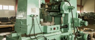
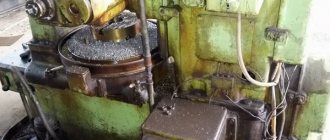
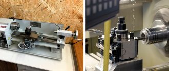
The thread-cutting machine (Fig. 1) is designed to create various thread designs, as well as other types of processing, on the internal and external surfaces of the workpieces being processed. Let's look at the device and principle of operation using the example of one of the most common semi-automatic thread cutting machines 5993.
Figure 1. Threading machine.
Figure 1. Threading machine.
This machine has a headstock. The rotational motion is transmitted from the electric motor through the gearbox. The gearbox, as a rule, on these machines is made in a simplified form with a small number of speeds.
The spindle of this machine has a screw-tapping head. The head is equipped with a drive that allows you to clamp and release the workpiece. Also attached to the head are so-called thread-cutting dies, which can vary depending on the required profile of the thread being created.
In place of the support there is a carriage. In it, the workpiece is fixed in a self-centering mechanism. The carriage is attached to the frame through rolling bearings. This allows her to move within specified limits.
A semi-automatic thread-cutting machine operates according to the following scheme.
- The workpiece is placed in the clamping device (vice) of the carriage. A signal is sent to the control panel. The electromechanical clamping device moves and clamps the workpiece. If the part has a large length or some other features that may cause misalignment, a special stop is used.
- The main engine of the machine turns on. The spindle and threading head begin to carry out working movements.
- A control signal is supplied to the carriage movement mechanism. A hydraulic cylinder extends and guides the carriage toward the headstock.
- The workpiece comes into contact with a rotating die head. The thread cutting process begins.
- When the carriage passes the calculated distance, which is limited by the stop, a control signal is sent to open the screw-cutting head. When the head opens, the automation starts the carriage in reverse motion.
- The machined part is removed from the vice and a new workpiece is installed. The cycle repeats.
Semi-automatic threading machines are rarely used in conveyor production due to the low automation of the threading process and the inability to load a large amount of raw materials at a time. The main area of application of this type of machines is piece and small-scale production.
For medium and large conveyor production, automatic thread-cutting machines with CNC are used (Fig. 2).
Figure 2. CNC thread tapping machine.
Figure 2. CNC thread tapping machine.
A CNC thread-cutting machine operates in conveyor production. Basically, the workpiece is a rod, pipe or hexagon. The turret type threading head can accommodate up to 26 threading cutters at a time.
How to choose a tool?
When choosing a tool for cutting threads on pipes, the master is guided by the design features of the pipeline, its technical characteristics and functionality.
The choice of hand or power tool depends on what material will be used for threading and how much work needs to be done. An important factor remains the price of threading tools and components. Expensive electrical plugs are bought by craftsmen who regularly cut external and internal threads. If the job is one-time, you should consider buying inexpensive hand tools.
A thread-cutting tool requires the presence of direct cutting elements - these are dies, taps, and cutters. For more advanced products designed for high-precision productive cutting, the working tool is a prefabricated adjustable thread-cutting head, including several cutting combs.
Types of equipment for thread-cutting tools
You can resolve this issue by reading a brief description of each type of tool.
The die is a nut with holes along its axes for the cutting edge and a hole for chip removal. It is usually used in everyday life and small-scale repair and construction work for cutting external threads on pipes.
The tap is used for the production of internal threads, used both in manual equipment and installed on machines.
The cutter and comb are usually made of high-alloy steel and are used in threading dies and machines for cutting internal and external threads.
The thread-cutting die with combs is gradually replacing the tool with a die (die) due to higher productivity and versatility. The clamps are manual and electric. They are suitable for cutting threads of different geometries - metric, inch, conical, with a certain, including variable, pitch.
The manual thread-cutting die is lightweight, compact, and easy to carry. It does not depend on power supply and is affordable.
Electric clamps are much more functional than manual ones. They cut threads faster and do not require much physical effort from the master. The volume of work performed per unit of time increases significantly. Note that in terms of thread cutting accuracy, high-quality manual dies are not inferior to electric ones.