Among all metalworking equipment, gear hobbing machines should be highlighted. In the accepted classification system they were placed in a separate group. Horizontal, vertical or other types of gear hobbing machines are used to produce an involute gear profile. Obtaining a complex surface is carried out by the rolling method.
Processing methods
The production of worm products is carried out by other methods. For processing, 2 types of plunge are used - radial and tangential.
- Radial processing method - carried out using a radial moving screw. During operation, one movement is performed (FU - B1B2), which divides and forms the surface of the teeth.
For radial processing, one plunge movement is used (BP - P7).
- The tangential processing method is used much less frequently than the radial method, but no worse.
The main working mechanisms are a tangential screw and a modular hob cutter with a fence-shaped cone.
To form teeth and dividing operations, the same movement is used as in the first method (FU - B1B2). But the side surfaces of the teeth are formed 2 times, the first has already been discussed, and the second occurs simultaneously with the cutting of the cutter into the workpiece.
For tangential cutting of the cutter, namely the conical part, the movement ФS2 – П5B6 is carried out.
Classification by drive type
Gear hobbing machines have a rather complex design. The drive type determines how the disk division can be calculated. Let's consider the features and parameters of the following common drive circuits:
- A group of gear hobbing machines with a dividing worm gear table. The equipment has variable coil thickness. The gap can be adjusted in the range of 0.03-0.05 mm with a significant displacement of the worm.
- When considering the description, attention should be paid to the location of the systems. The peculiarities of this scheme consist in mounting a separate housing for the dividing gear. In this case, the crowns are divided by adjusting the gap. The worm moves with the worm in a radial direction relative to the wheel.
- It is also possible to run in a workpiece by gear hobbing when installing two worm gears with different directions of turns. This adjustment method is universal and is represented by an axial displacement of one of the worms. The center can shift a certain distance depending on the features of the model.
- There are models on which a gear unit is installed. The gear wheel is driven by a hydraulic pump.
- The cylindrical type of gear can be mounted on a cutter spindle, which is represented by two halves. The gap is set by moving the wheel halves relative to each other.
- Considering the drawing of various machines, we note a design option when both gears of the spindle cutter have a small taper of the teeth. In this case, gear-processing equipment can be controlled by moving one wheel in the axial direction.
- The cutter spindle can accommodate a gear with a very large number of teeth. When carrying out the calculation, we note that the adjustment is carried out by slowing down the rotation relative to the main wheel.
In addition, other options for transmitting rotation have appeared. Some are suitable for single-unit production.
Machining on a hobbing machine with a hob cutter
Main technical parameters
This type of machine has a large number of technical characteristics. At the same time, setting up a gear hobbing machine allows you to change some parameters and use one panel to produce gears with different parameters.
Gear hobbing machines have the following technical parameters:
- Setting up a gear hobbing machine taking into account the diameter of the crown and the maximum size of the tooth module
- An important indicator is the width of the ring gear.
- By calculating the differential pattern of a gear hobbing machine, you can set the processing mode when cutting teeth at an angle. In this case, the angle can be set in a specific range.
- Considering the universal gear hobbing machine, we note that the design has a support that moves in the vertical and transverse direction. An important point is the maximum movement rate.
- The classic device of a gear hobbing machine has a unit where the cutting tool is fastened. Manual setting or installed CNC systems for gear hobbing machines can set the rotation speed of the cutting tool within a certain range.
- The installed gear hobbing machines have technical characteristics that determine the feed range. It can be manual or mechanical, vertical, tangential and radial.
- The operating principle is based on the transmission of rotation from the main electric motor through the drive to the cutting tool and workpiece clamping. Therefore, one of the main indicators is the power of the main electric motor. In addition, a horizontal or vertical gear hobbing machine may have several motors, each responsible for performing specific tasks.
- Different gear hobbing machines have different overall dimensions. It is worth considering the fact that the dimensions of the equipment determine not only the features of its installation, but also some performance qualities. So, with an increase in overall dimensions, the stroke of the support and cutting tool often increases, and the dimensions of the table increase.
- Weight can vary over a wide range.
Guitar tuning formulas for gear hobbing machines
The division pattern of a gear hobbing machine can vary significantly depending on the features of a particular model. This should be taken into account when calculating the division guitar of a gear hobbing machine.
Machine examples
For example, let's take the 53A50, 53A50H, 53A80H and 53A80 vertical gear hobbing machines.
They are based on several plunge methods and are used for processing several types of materials at once, both worm products and cylindrical wheels.
The machines are suitable for mass production and the home workshop.
In the following sections you will be able to familiarize yourself in detail with the design of some machines, as well as study the equipment passport.
Where are they used?
Gear hobbing machines differ in some characteristics, and they are used:
- in instrument making;
- in the engineering industry;
-in the aviation and automotive industries.
Due to the fact that processing does not allow changing the diametrical size of cylindrical products, a universal type gear hobbing machine is installed with other metalworking equipment. There are models that can be used in such productions as: serial, small-scale and large-scale.
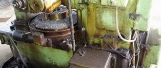
Design of semi-automatic gear hobbing machines 5K32 and 5K32A
Below we will look at a detailed description of each model of gear hobbing equipment.
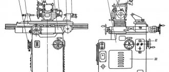
Workspace dimensions
The 5K32A model has larger dimensions than the 5K32, which means that much more work space will be needed. Now it’s clear why Model A is less suitable for home workshops.
Working space dimensions 5K32 and 5K32A. Scheme:
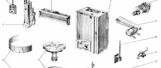
Landing and connecting bases
If you look at the picture shown below, you can see that the layout of the landing and connecting bases is almost the same for each model.
The 5K32A model has a slight difference, which is also due to its large dimensions.
Landing and connecting bases. Scheme:
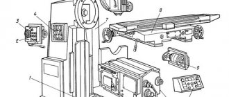
Location of controls
The machine models are almost identical in structure, which means the location of the control mechanisms is identical.
Location of controls. Scheme:
Computer numerical control
Setting up the gear divisions of a gear hobbing machine is done to change the parameters of the cut teeth. CNC gear hobbing machines have main components that can be adjusted to the cutting conditions; they have high movement accuracy. CNC machines can be characterized as follows:
- Can be used for cutting bevel gears and bevel wheels. Numerical control allows you to set the main processing modes.
- When drawing up a processing program, all parameters are calculated. However, the division of the crown occurs differently; tuning of the guitar is not required. This is due to the fact that a vertical gear hobbing machine or a horizontal type with CNC has movable units, the position of which and the main performance indicators are adjusted by the created program.
Modern equipment does not require significant operator intervention, since the division guitar is often absent. Such gear cutting models are expensive and difficult to maintain. Therefore, it is most often advisable to install and use a processing machine where there is a differential guitar design.
Yuri Davydov » News
Gear hobbing machines. Design, description and technical characteristics.
Gear hobbing machines are designed for cutting cylindrical wheels with straight and helical teeth of external gear using shaped disk, finger and worm modular cutters. If a gear hobbing machine has, in addition to a vertical lead screw, radial or tangential movement of the tool relative to the workpiece, then it can also cut worm wheels with hob cutters. A machine that has all three of the above screws is classified as a universal gear hobbing machine.
On gear hobbing machines, cylindrical and worm wheels are cut using the rolling method and the copying method with axial, radial-axial and tangential feeds in one or two working strokes. Depending on the location of the axis of the product, the machines are divided into vertical ones (they consist of a bed, a tool stand, a milling support, a rear table stand for installing the product. Vertical machines are made with a stand movable in the radial direction or with a table movable in this direction, as well as with a table movable in the vertical direction.The layout of machines with a movable stand and a fixed table is most convenient for automating the gear cutting process.
Horizontal machines designed for cutting teeth on heavy parts are made with a tool stand movable in the horizontal direction, and machines for cutting small wheels are made with a movable table carrying the product.
Technical data of gear hobbing machines
The tooth profile is formed by copying or rolling, the tooth shape along the length is formed by touching. Gear hobbing machines of the copying method have a simple structure consisting of groups: ФV(В1), ФS(П2), as well as division Д(В3). Touch-rolling machines have two or three shaping groups and do not have a division group: tooth profile: ФV(В1 В2); length shape: straight teeth: ФS(П3), helical: ФS(П3 В4).
The copying method, when the cutting edges of the tool correspond to the shape of the cavity of the gear wheel and after cutting one cavity, the workpiece is rotated by one tooth using a dividing device, the rolling method (the processing tool reproduces the movement of a pair of gear wheels), hot and cold rolling.
The shaping of worm wheel teeth is carried out using radial and tangential cutting methods. The first method uses a radial displacement screw. The formation of the side surfaces of the teeth along the profile and length, as well as the dividing process, is carried out in one complex movement Фu, (В1В2). The process of radial cutting of the cutter teeth into the workpiece is carried out by the movement Вр (П7). The second method uses a tangential screw and a special hob cutter with a intake cone. The formation of the profile and shape of the tooth along the length, as well as the dividing process, is carried out, as in the first method, by the movement Фu (В1В2). The second movement Фs2 (П5В6) carries out tangential incision due to the conical part of the cutter and once again the formation of the side surfaces.
Semi-automatic vertical gear hobbing machines 53A50, 53A50N, 53A80, 53A80N are designed for cutting cylindrical and worm gears in individual and mass production.
Gear hobbing semi-automatic models 53A50, 53A80 are manufactured according to class P GOST 8-71, and their modifications according to class N GOST 8-71. Machines of models 53А50, 53А80 are equipped with supports with continuous movement of the cutter (with a slide), and models 53А50Н, 53А80Н - with supports with periodic (step) movement of the cutter. At the Buyer's request, gear hobbing machines can be equipped with a CNC system.
The universal gear hobbing machine is designed for milling cylindrical spur, helical and worm wheels in single and batch production. The cutting of gears is carried out using the method of running in a hob cutter and the workpiece being processed. The machine operates in a closed semi-automatic cycle and an adjustment cycle.
On the basis of the machine, special machines can be manufactured that allow processing wheels with barrel-shaped or conical teeth. Processing is carried out by copying according to a template.
The great versatility of the machines and the high degree of automation ensure that the machines operate in both single-pass and double-pass automatic cycles. With a two-pass automatic cycle, there is an automatic change of processing modes. The semi-automatic machine has a stepless drive of vertical and radial feed.
Typical structural layouts
When considering a gear hobbing machine and the principle of its operation, it is important to pay attention to its layout. Based on this indicator, the following groups are distinguished:
- Vertical orientation of the workpiece axis. The layout of gear hobbing machines determines the processing features; they have a movable table. The layout is used in the production of universal models, which are most widespread.
- Vertical orientation of the workpiece axis, the tool is movable horizontally. The device of this gear hobbing machine has a tool support through which axial feed is transmitted. This arrangement is most suitable for models equipped with an automation system for loading/unloading workpieces. Similar CNC gear hobbing machines, the operating principle of which involves automatic feeding of the workpiece, have become widespread in the production of large batches of products.
- Gear hobbing machines when placing the workpiece in the vertical direction. Considering the main components, we note the table, which is often movable in the vertical direction. Radial feed is carried out by a tool stand. These gear hobbing machines, the models of which can vary significantly depending on the purpose, have a design that allows them to be easily integrated into various automatic processing lines. Processing on modern gear hobbing machines comes down to reducing the number of operations requiring operator intervention.
- Horizontal with the workpiece axis placed in this plane. The table is movable in this direction and transmits axial rotation. The tool is mounted on a tool stand. A gear hobbing machine of this type is widely used in the field of cutting fine-module gears. The design has horizontal guides to ensure movement of the tool rack.
- Horizontal machines have a mount for placing the workpiece in a certain plane. The key feature is the immobility of the table. The tool rack is movable, designed to transmit axial and radial feed. These types of equipment make it possible to process gears made as a single structure with a shaft.
The calculation of the differential of a gear hobbing machine is carried out depending on the features of the circuit. The differential method is quite common.
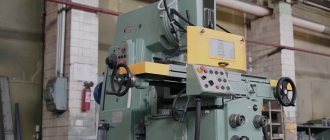
Semi-automatic gear hobbing machine 5M324A
Purpose
Semi-automatic gear hobbing mod. 5M324A is designed for milling teeth of cylindrical spur and helical gears, as well as worm wheels in medium and large-scale production. In terms of accuracy, the machine is manufactured in accordance with the requirements of GOST 659 - 78 for class N. The high versatility of the machine ensures operation in an automatic cycle with radial cutting, up and down milling.
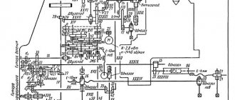
Kinematic chains
Main movement chain: electric motor 70, gears 1 - 2-3, replaceable guitar wheels of speeds a - b (shafts I, II, III), wheels 4-5, 22-23, shaft V, wheels 42-43, 44- 45, shaft VII (mill).
Table rotation chain: 70 electric motor, 1-2-3 gears, a1-b1 replacement wheels, 4-5, 6-7, 8-9-10 wheels, differential, 13-14 gears, ef wheels, a2 replacement guitar wheels -b2, c2-d2, wheels 15 - 16, 60 - 61, worm pair 62 - 63. Wheel 63 is closely connected to the table.
A dividing chain connecting the rotational movement of the cutter and the table: wheels 45-44, 43-42, 23-22, 6-7, 8-10, differential, wheels 13-14, ef wheels, replacement guitar wheels division a2-b2,, c2-d2wheels 15-16, 60-61, worm gear 62-63.
Vertical feed chain: worm - pair 63-62, wheels 61-60, 16-15, worm gear 17-50, - wheels 58-57, replaceable guitar feed wheels a3 -b3, wheels 56-55, 33-28, worm gear 25-18, vertical feed screw with pitch t1 = 10 mm.
Accelerated vertical feed is carried out along the chain: electric motor 73, chain drive 21-59, wheels 54-53, 30-28, worm gear 25 -18, vertical feed screw with pitch t1 = 10 mm.
The radial feed chain for cutting worm wheels goes from the table through a worm pair 63-62, wheels 61-60,16-15, worm pairs 17-50, 58-57, replaceable wheels a3-b3, wheels 56-55, 33-34 , 31-32, worm gear 35-36 pa radial feed screw X with pitch t2 = 10 mm.
The machine has an additional chain connecting the rotation of the table and the rotation of the cutter. The beginning of this chain is the table, then follows the gearbox 63-62, wheels 61-60, 16-15, worm gear 17-50, wheels 58-57, feed box with replaceable gears a3-b3, wheels 54-53, 30 -28, conical pair 27-26, differential guitar a2 -b2, c2 -d2, wheels 19-20, worm pair 11 - 12, differential mechanism, bevel wheels 7-6, 22-23, 42-43, on wheels 44 -45 - spindle. This chain is activated when cutting cylindrical helical gears.
Rice. 34 Kinematic diagram of the machine mod. 5M324A
Setting up semi-automatic machine 5M324
To ensure normal operation of the machine, before starting it, it is necessary to check the correct installation of the workpiece on the table and the installation of the cutter, determine the milling depth and the settings of the replacement wheels. The workpiece is mounted on special mandrels and checked for runout with an indicator. The permissible runout value is 0.01-0.02 mm. After fastening, the workpiece is checked for runout along the outer diameter and end.
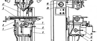
When cutting straight-toothed cylindrical wheels, the hob cutter is installed obliquely at an angle φ to the horizontal plane equal to the angle β of the helix of the cutter (Fig. 35,a). When cutting helical wheels, the angle of inclination of the cutter is φ= α± β, where α is the angle of inclination of the teeth of the wheel being cut to its axis. The plus sign will be for opposite directions of the helical lines of the teeth of the cut wheel and the cutter (Fig. 35, c), and the minus sign will be for the same directions (Fig. 35, b). It is recommended to select a cutter with the same direction of the helix as the teeth of the wheel being cut; this improves processing accuracy. When cutting worm wheels, the cutter is installed horizontally, i.e. φ = 0.
Rice. 35 Setting the cutter relative to the workpiece
Functionality
Using a CNC gear hobbing machine, the following types of gears are produced:
- straight teeth;
- helical;
— splined shafts;
— chain sprockets;
— rims of worm and ratchet wheels;
— chevron wheels, etc.
The main cutting movement is a rotational movement. The actions of the cutting tool lead to synchronous rotation of the feed table, thereby achieving the required number of teeth on the cut crown. When the cutter moves along the axis of the wheel, gears are cut along the width of the workpiece.
On CNC machines, products are processed using the following methods:
-using counter or passing serves;
-using a circular or axial insertion with diagonal or axial feed;
-using a two-pass cycle with automatic insertion.
At the same time, the spindle rotation speed changes steplessly.