Information about the manufacturer of the 6T12-1 cantilever milling machine
The manufacturer of the 6T12-1 series of universal milling machines is the Gorky Milling Machine Plant , founded in 1931.
The plant specializes in the production of a wide range of universal milling machines, as well as milling machines with DRO and CNC, and is one of the most famous machine-tool enterprises in Russia.
Since 1932, the Gorky Milling Machine Plant has been producing machine tools and is an expert in the development and production of various metal-cutting equipment.
Products of the Gorky Milling Machine Plant GZFS
- 6G605
double-spindle longitudinal milling machine, 500 x 1600 - 6M12P
vertical cantilever milling machine, 320 x 1250 - 6M13P
vertical cantilever milling machine, 400 x 1600 - 6M82
universal horizontal milling machine, 320 x 1250 - 6M82G
horizontal cantilever milling machine, 320 x 1250 - 6М82Ш
universal cantilever milling machine, 320 x 1250 - 6M83
universal horizontal milling machine, 400 x 1600 - 6M83G
horizontal cantilever milling machine, 400 x 1600 - 6М83Ш
horizontal cantilever milling machine, 400 x 1600 - 6N12
vertical cantilever milling machine, 320 x 1250 - 6N13P
vertical cantilever milling machine, 400 x 1600 - 6N82
horizontal cantilever milling machine, 320 x 1250 - 6N82G
horizontal cantilever milling machine, 320 x 1250 - 6Р12, 6Р12Б
vertical cantilever milling machine, 320 x 1250 - 6Р13, 6Р13Б
vertical cantilever milling machine, 400 x 1600 - 6Р13Ф3
vertical cantilever milling machine with CNC, 400 x 1600 - 6Р82
universal horizontal milling machine, 320 x 1250 - 6R82G
horizontal cantilever milling machine, 320 x 1250 - 6Р82Ш
universal cantilever milling machine, 320 x 1250 - 6Р83
universal horizontal milling machine, 400 x 1600 - 6R83G
horizontal cantilever milling machine, 400 x 1600 - 6Р83Ш
universal cantilever milling machine, 400 x 1600 - 6T12-1
vertical cantilever milling machine, 320 x 1250 - 6T12
vertical console-milling machine, vertical, 320 x 1250 - 6T12F20
vertical cantilever milling machine with CNC, 320 x 1250 - 6T13
vertical cantilever milling machine, 400 x 1600 - 6T13F20
vertical cantilever milling machine with CNC, 400 x 1600 - 6T13F3
vertical cantilever milling machine with CNC, 400 x 1600 - 6T82
universal horizontal milling machine, 320 x 1250 - 6T82-1
universal horizontal milling machine, 320 x 1250 - 6T82G
horizontal cantilever milling machine, 320 x 1250 - 6Т82Ш
universal cantilever milling machine, 320 x 1250 - 6T83
universal horizontal milling machine, 400 x 1600 - 6T83-1
universal horizontal milling machine, 400 x 1600 - 6T83G
universal horizontal milling machine, 400 x 1600 - 6Т83Ш
universal cantilever milling machine, 400 x 1600 - 6605
double-spindle longitudinal milling machine, 500 x 1600 - 6606
three-spindle longitudinal milling machine, 630 x 2000 - GF2171
vertical milling machine with CNC and ASI, 400 x 1600
6T12-1 vertical cantilever milling machine. Purpose and scope
6T12-1 vertical cantilever milling machine has been produced since 1985 and replaced the outdated 6P12 model in production.
In 1985, the Gorky Milling Machine Plant (GZFS) began production of cantilever milling machines of the 6t12-1 series. Machines of the 6t12-1 series are a further improvement of similar machines of the P series (6P12, 6P13).
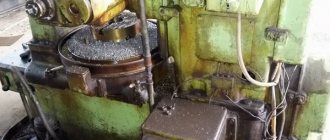
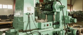
The vertical cantilever milling machine 6T12-1 is designed for milling all kinds of parts from various materials. It is used in single and serial production.
6T12-1 cantilever milling machine differs from the 6T13-1 machine in the installed power of the main movement and feed motors, the dimensions of the working surface of the table and the amount of table movement.
6T12-1 milling machine can process vertical and horizontal planes, grooves, corners, frames, gears, etc.
6T12-1 vertical cantilever milling machine can operate in three modes:
- Automatic - In automatic mode, the machine operates at various automatic cycles.
- Jog — In jog mode, adjustment movements of the table are made. Marking work is possible.
- Manual - In the manual universal mode, the machine operates using working feeds, rapid movements, as well as manual movements from the flywheels and handle.
Design features of the 6T12-1 milling machine
The technological capabilities of machines can be expanded through the use of overhead milling, dividing and slotting heads, and a round rotary table.
There is a device for limiting the gap in the screw pair for the longitudinal movement of the table, individual lubrication of the vertical movement screw, which increases its durability and reduces the lifting force of the console.
Additional devices have been introduced to protect against flying chips and emulsions .
The rigidity of the machine has been increased due to the rectangular guides of the bed and console.
There is automatic spindle braking in operating mode and during emergency shutdown.
Automated lubrication of components increases their durability and reduces maintenance time.
The rotating spindle head of the machine is equipped with a mechanism for manual axial movement of the spindle sleeve, which allows processing of holes whose axis is located at an angle of up to ±45° to the working surface of the table.
The drive power and high rigidity of the machines allow the use of cutters made of high-speed steel, as well as tools equipped with plates made of hard and super-hard synthetic materials.
Tool fastening is mechanized . The cross-feed screw is located along the axis of the cutter, which increases processing accuracy. The technological capabilities of the machine can be expanded with the use of a dividing head, a rotary round table and other devices.
The ability to configure the machine for various semi-automatic and automatic cycles allows you to organize multi-machine maintenance and use the machine to perform various jobs in continuous production.
The machine can be supplied to countries with temperate, cold and tropical climates.
Machine accuracy class - N according to GOST 8-82E
The main design advantages of the machines:
- mechanized tool fastening in the spindle;
- proportional feed deceleration mechanism;
- a device for periodically adjusting the size of the gap in the longitudinal feed screw pair;
- safety clutch protecting the feed drive from overloads;
- braking of the horizontal spindle when stopping using an electromagnetic clutch;
- protection device against flying chips.
Main technological advantages of the machines:
- various automatic machine operation cycles;
- wide range of spindle speeds and table feeds;
- high drive power;
- high rigidity;
- reliability and durability.
- The technological capabilities of machine tools can be expanded by using a dividing head, a round rotary table and other devices.
The machines are produced in various versions according to voltage and frequency of the supply network. Spare parts are supplied.
The main differences between the 6T12-1 (1985) and 6T12 (1991) milling machines
- Overhang (distance from the spindle axis to the bed guides): 6t12-1 - 350 mm, 6t12 - 380 mm
- Transverse movement of the table: 6t12-1 - 270 mm, 6t12 - 320 mm
- Distance from the edge of the table to the frame: 6t12-1 - 70..340 mm, 6t12 - 70..390 mm
The working space of the machine model 6t12 is 50 mm larger along the X, Y axes than that of the machine 6t12-1.
Modifications of console-milling machines of the “T” series
Various modifications and specialized machines have been developed based on the “T” series machines:
- 6T12 - 6T12-27, 6T12-29, 6T12-30
- 6Т13 - 6Т13-27, 6Т13-29, 6Т13-30
- 6T82G - 6T82G-27 (GF2793), 6T82G-29, 6T82G-30
- 6T83G - 6T83G-27 (GF2797), 6T83G-29, 6T83G-30
- 6T82 - 6T82-27 (GF2794), 6T82-29, 6T82-30
- 6T83 - 6T83-27 (GF2798), 6T83-29, 6T83-30
- 6T82Sh - 6T82Sh-27, 6T82Sh-29, 6T82Sh-30, 6T82Sh-35, 6T82Sh-36, 6T82Sh-37, 6T82Sh-38
- 6T83Sh - 6T83Sh-27, 6T83Sh-29, 6T83Sh-30, 6T83Sh-35, 6T83Sh-36, 6T83Sh-37, 6T83Sh-38
Modifications 6T...-27 have a 100 mm increased distance from the spindle axis (end) to the working surface of the table and a mechanism for proportional (2 times) slowdown of the working feed.
Russian and foreign analogues of the 6T12-1 (6T13-1) machine
FSS350MR, FSS450MR - 315 x 1250, 400 x 1250 - manufacturer Gomel Machine-Tool Plant
VM127M - (400 x 1600) - manufacturer Votkinsk Machine-Building Plant GPO, Federal State Unitary Enterprise
6D12, 6K12 - 320 x 1250 - manufacturer Dmitrov milling machine plant DZFS
X5032, X5040 - 320 x 1320 - manufacturer Shandong Weida Heavy Industries, China
FV321M, (FV401) - 320 x 1350 (400 x 1600) - manufacturer Arsenal JSCo. — Kazanlak, Arsenal AD, Bulgaria
History of production of machine tools by the Gorky plant, GZFS
In 1937
, the Gorky
Milling Machine Plant produced the first cantilever milling machines of the 6B series, models 6B12 and 6B82 , with a work table of 320 x 1250 mm (2nd standard size).
In 1951
6N of cantilever milling machines was launched into production 6N13PR machine received the “Grand Prix” at the world exhibition in Brussels in 1956.
In 1960
6M cantilever milling machines
was launched into production In 1972
6P of cantilever milling machines
was put into production In 1975
year, copying cantilever-milling machines were launched into production:
6Р13К .
In 1978
In 2009, copying cantilever-milling machines
6Р12К-1 , 6Р82К-1 .
In 1985
6T-1 of cantilever milling machines was put into production 6T13-1 , 6T82-1, 6T83-1 and GF2171.
In 1991
6T of cantilever milling machines was put into production
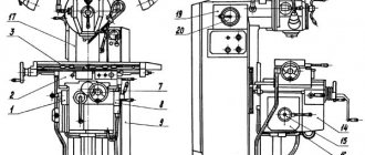
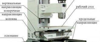
Location of components of the 6T12-1 cantilever milling machine
Location of components of the milling machine 6t12-1
List of components of the cantilever milling machine 6t12-1
- bed
- side remote control
- feed switch mechanism
- spindle gearbox
- rotating head
- electromechanical tool clamping devices
- control cabinet
- table and sled
- feed delay mechanism
- main remote control
- console
- gearbox
Certificate of vertical milling machine 6T12F20-1 with digital display LUMO-61
This instruction manual “Cantilever vertical milling machine with operational program control 6T12F20-1 ” contains information necessary both for the maintenance personnel of this machine and for the employee directly involved in working on this machine. This manual is an electronic version in PDF format of the original paper version. This documentation contains the Passport and Manual (instructions) for the operation of the universal screw-cutting lathe 6T12F20-1 . Contents of this documentation:
GENERAL INFORMATION
MAIN TECHNICAL DATA AND CHARACTERISTICS
Contents of delivery
SAFETY INSTRUCTIONS
COMPOSITION OF THE MACHINE
INSTALLATION PROCEDURE
DEVICE AND OPERATION OF THE MACHINE AND ITS COMPONENTS
Lubrication system
INSTALLATION PROCEDURE
Possible malfunctions and methods for eliminating them
FEATURES OF DISASSEMBLY AND ASSEMBLY DURING REPAIR
Maintenance and repair instructions
Spare parts materials
You can download the passport of the console vertical milling machine 6T12F20-1 (32 sheets) in good quality from the link below. Since this machine is built on the LUMO-61 digital display device, in addition to this passport, documentation on the LUMO-61 control unit is required.
Documentation on the OPU LUMO-61 system. Download for free. (Link is temporarily not working)
You can download the passport of the console vertical milling machine 6T12F20-1 (53 sheets) in good quality from the link below.
Control panels for milling machine 6T12-1
Control panels for milling machine 6T12-1: main -II, side -I
List of controls for the 6T12-1 cantilever milling machine
- Spindle speed indicator
- Button “Move table back, forward, down”
- Switch for selecting the direction of table movement
- Switch “Clamp-Release Tool”
- Button “Move table forward, left, up”
- Spindle Jog button (duplicate)
- Button “Stop table movement”
- Spindle start button
- “Spindle Stop” button (duplicate)
- Emergency Stop button
- Button “Fast table movement” (duplicate)
- Spindle speed shift knob
- —
- Hexagon head rotation
- Spindle sleeve clamp handle
- Key "Move table left"
- "Move table to the right" key
- Key "Stop longitudinal movement of the table"
- Spindle Stop button
- Spindle start button
- Table Clamps
- Switch for switching on the table operating mode “Manual - Mechanical”
- Flywheel for manual longitudinal movement of the table
- Vernier ring
- Limb of the table transverse movement mechanism
- Manual lateral movement of the table
- Manual vertical table movement
- Feed switch mushroom
- Emergency Stop button
- Machine operating mode selection switch
- Slow feed switch
- Button “Fast table movement and cycle start”
- “Stop vertical table movement” key
- "Move table down" key
- Slide Clamps
- "Move table up" key
- Flywheel for manual longitudinal movement of the table (duplicate)
- Key "Stop lateral movement of the table"
- "Move table forward" key
- "Move table back" key
- Spindle sleeve extension flywheel
- Clamping the head on the frame
- Input switch
- Spindle rotation direction switch “Left - Right”
- Cooling pump switch "On - Off"
- Control panel selection switch
- Auto cycle selection switch
- Console Clamp
- Removable handle for manual vertical and transverse movement of the table
- Zero head fixation pin
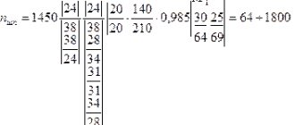
Kinematic diagram of the 6T12-1 cantilever milling machine
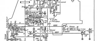
Kinematic diagram of the 6T12-1 cantilever milling machine
The kinematic diagram is given to understand the connections and interactions of the main elements of the machine. The numbers of teeth (g) of the gears are indicated on the callouts (the asterisk indicates the number of starts of the worm).
The main movement is driven by a flange electric motor through an elastic coupling.
The spindle speed is changed by moving three toothed blocks along the splined shafts.
The gearbox provides the spindle with 18 different speeds.
The feed drive is carried out from a flange electric motor mounted in the console. By means of two three-crown blocks and a movable gear wheel with a cam clutch, the feed box provides 18 different feeds, which are transmitted through a ball safety clutch to the console and then, when the corresponding cam clutch is engaged, to the screws of longitudinal, transverse and vertical movements.
Accelerated movements are obtained when the high-speed clutch is turned on, the rotation of which is carried out through intermediate gears directly from the feed electric motor.
The clutch is interlocked with the working feed clutch, which eliminates the possibility of their simultaneous activation.
Graphs explaining the structure of the machine feed mechanism are shown in Fig. 6 and 7.
Features of disassembling machines 6р81г
On machines, it is difficult to dismantle the feed box and gearbox from the console. Dismantling requires complete disassembly of the console, which must be carried out in the following order:
- unfasten the sled strips and the table cross-travel nut bracket, remove the table;
- lift the console all the way up and place a reliable support under it;
- open the cover and remove the nut from the upper end of the vertical movement screw; Unfasten the screw casing flange from the bottom of the console; unfasten the column from the base and screw it onto the screw; remove the screw with the casing and bevel gear from the console;
- Unfasten and remove the feed switch mechanism;
- unfasten and remove the reverse box from the console;
- disconnect the lubrication lines from the pump;
- remove the overspeed handle and console cover;
- drain the oil from the console cavity;
- remove the feed box along with the gearbox.
Design of the main components of the 6T12-1 cantilever milling machine
bed
The bed is the base unit on which the remaining components and mechanisms of the machine are mounted.
The frame is rigidly fixed to the base and fixed with pins.
Rotating head of cantilever milling machine 6T12-1
The rotating head (Fig.) is centered in the annular recess of the bed neck and is attached to it with four bolts that fit into a single groove in the bed flange.
The spindle is a two-support shaft mounted in a retractable sleeve. The axial play in the spindle is adjusted by grinding rings 3 and 4. Increased play in the front bearing is eliminated by grinding half rings 5 and tightening the nut.
The adjustment is carried out in the following order:
- the spindle sleeve extends;
- flange 6 is dismantled;
- half rings are removed;
- a screw plug is removed from the right side of the head body;
- through the hole, unscrewing screw 2 unlocks nut 1;
- Nut 1 is locked with a steel rod. By turning the spindle by the nut, the nut is tightened and this moves the inner race of the bearing. After checking the play in the bearing, the spindle is run in at maximum speed. When operating for an hour, the heating of the bearings should not exceed 60° C;
- the size of the gap between the bearing and the spindle collar is measured, after which the half rings 5 are ground to the required amount;
- the half rings are put in place and secured;
- Flange 6 is screwed in.
To eliminate radial play of 0.01 mm, the half rings must be ground by approximately 0.12 mm.
Rotation is transmitted to the spindle from the gearbox through a pair of bevel and a pair of cylindrical gears mounted in the head.
The bearings and gears of the rotary head are lubricated from the frame pump, and the spindle bearings and the sleeve moving mechanism are lubricated by extrusion.
Gearbox
The gearbox is mounted directly in the frame body. The connection of the box to the electric motor shaft is carried out by an elastic coupling, which allows misalignment in the motor installation of up to 0.5-0.7 mm.
The gearbox can be inspected through the window on the right side.
The gearbox is lubricated by a plunger pump (Fig. 9), driven by an eccentric. Pump capacity is about 2 l/min. Oil is supplied to the pump through a filter. From the pump, the oil flows to the oil distributor, from which it is discharged through a copper tube to the pump control eye and through a flexible hose to the rotary head. The gearbox elements are lubricated by splashing oil coming from the holes in the oil distributor tube located above the gearbox.
Gearbox
The gearbox allows you to select the required speed without sequentially passing through intermediate stages.
Rack 19 (Fig. 10), moved by shift handle 18, through sector 15 through fork 22 (Fig. 11) moves the main roller 29 with shift disc 21 in the axial direction.
The shift disk can be turned by the speed indicator 23 through the bevel gears 28 and 30. The disk has several rows of holes of a certain size located against the pins of the racks 31 and 33.
The racks engage in pairs with gear 32. A shift fork is attached to one of each pair of racks. When moving the disk by pressing on the pin of one of the pair, reciprocating movement of the slats is ensured.
In this case, the forks at the end of the disk stroke occupy a position corresponding to the engagement of certain pairs of gears. To eliminate the possibility of hard stop of the gears when switching, the pins of 20 racks are spring-loaded.
Fixation of the dial when choosing a speed is ensured by ball 27, which slides into the groove of sprocket 24.
The spring 25 is adjusted by the plug 26, taking into account the clear fixation of the dial and the normal force when turning it.
Handle 18 (see Fig. 10) is held in the on position by spring 17 and ball 16. In this case, the handle tenon fits into the groove of the flange.
Correspondence of speeds to the values indicated on the indicator is achieved by a certain position of the bevel wheels along the mesh. Correct engagement is established by cores at the ends of the mating tooth and cavity or by setting the pointer to the speed position of 31.5 rpm and the disk with forks to the speed position of 31.5 rpm (for machine models 6T12B the corresponding speed is 50 rpm) . The gap in the engagement of the conical pair should not be more than 0.2 mm, since the disk can rotate up to 1 mm due to this.
The gearbox is lubricated from the gearbox lubrication system by splashing oil.
Composition and design of the 6T82G milling machine
Composition and design of the 6T82G milling machine
Basic assembly units of the machine
The components and mechanisms of the machine are mounted on the main assembly unit - the frame. The structure is rigid due to the base and a large number of ribs. A console moves along the vertical directions of the frame, the travel of which is limited by attaching a bar with cams on the left side of the frame. The console combines all nodes of the machine feed chain. The trunk with the earring moves in horizontal directions. An electrical cabinet is installed on the right side.
There is an oil reservoir inside the frame body, and a coolant supply pump is attached to the base on which it is installed.
The gearbox is mounted in the frame housing. The connection of the box to the electric motor shaft is carried out by an elastic coupling.
The machine spindle is a double-bearing shaft on bearings.
The gearbox allows you to select the required speed and start working with it without intermediate modes.
This is interesting: Wood milling - equipment, tools, artistic techniques
Technical characteristics of the cantilever milling machine 6T12-1
| Parameter name | 6Р12 | 6Р13 | 6Т12-1 | 6Т13-1 |
| Basic machine parameters | ||||
| Table surface dimensions, mm | 1250 x 320 | 1600 x 400 | 1250 x 320 | 1600 x 400 |
| Maximum mass of the workpiece, kg | 250 | 300 | 400 | 630 |
| Maximum longitudinal stroke of the table (X), mm | 800 | 1000 | 800 | 1000 |
| Maximum transverse travel of the table (Y), mm | 250 | 300 | 270 | 340 |
| Maximum vertical travel of the table (Z), mm | 420 | 420 | 420 | 430 |
| Distance from the end of the spindle to the table surface, mm | 30..450 | 30..500 | 30..450 | 70..500 |
| Distance from the spindle axis to the vertical guides of the bed (overhang), mm | 350 | 420 | 350 | 420 |
| Distance from the edge of the table to the vertical guides of the frame, mm | 70..340 | 60..400 | ||
| Spindle | ||||
| Main drive drive power, kW | 7,5 | 10 | 7,5 | 11 |
| Spindle speed, rpm | 40..2000 | 40..2000 | 31,5..1600 | 31,5..1600 |
| Number of spindle speeds | 18 | 18 | 18 | 18 |
| Spindle quill movement, mm | 70 | 80 | 70 | 80 |
| Movement of the spindle quill by one dial division, mm | 0,05 | 0,05 | 0,05 | 0,05 |
| Spindle head rotation angle, degrees | ±45° | ±45° | ±45° | ±45° |
| Spindle end GOST 836-62 | №3 | №3 | ||
| Spindle end GOST 24644-81, row 4, version 6 | 50 | 50 | ||
| Desktop. Submissions | ||||
| Limits of longitudinal and transverse table feeds (X, Y), mm/min | 12,5..1600 | 12,5..1600 | 12,5..1600 | 12,5..1600 |
| Limits of vertical table feeds (Z), mm/min | 4,1..530 | 4,1..530 | 4,1..530 | 4,1..530 |
| Number of table feeds (longitudinal, transverse, vertical) | 22 | 22 | 22 | 22 |
| Speed of fast movements (longitudinal, transverse/vertical) X, Y/ Z, m/min | 4/ 1,330 | 4/ 1,330 | 4/ 1,330 | 4/ 1,330 |
| Movement of the table by one dial division (longitudinal, transverse, vertical), mm | 0,05 | 0,05 | 0,05 | 0,05 |
| Table movement per one revolution of the dial (longitudinal, transverse/vertical), mm | 6/ 2 | 6/ 2 | 6/ 2 | 6/ 2 |
| Maximum permissible cutting force (longitudinal/transverse/vertical), kN | 15/ 12/ 5 | 20/ 12/ 8 | ||
| Machine mechanics | ||||
| Feed stops (longitudinal, transverse, vertical) | Eat | Eat | Eat | Eat |
| Blocking manual and mechanical feeds (longitudinal, transverse, vertical) | Eat | Eat | Eat | Eat |
| Blocking separate feed switching | Eat | Eat | Eat | Eat |
| Spindle braking | Eat | Eat | Eat | Eat |
| Overload safety clutch | Eat | Eat | Eat | Eat |
| Automatic intermittent feed | Eat | Eat | Eat | Eat |
| Electrical equipment and machine drives | ||||
| Number of electric motors on the machine | 4 | 4 | 4 | 4 |
| Main motion electric motor, kW | 7,5 | 10 | 7,5 | 11 |
| Feed drive electric motor, kW | 2,2 | 3,0 | 2,2 | 3,0 |
| Tool clamping motor, kW | 0,18 | 0,18 | ||
| Coolant pump electric motor, kW | 0,125 | 0,125 | 0,12 | 0,12 |
| Total power of all electric motors, kW | 10,0 | 14,3 | ||
| Dimensions and weight of the machine | ||||
| Machine dimensions (length width height), mm | 2305 x 1950 x 2020 | 2560 x 2260 x 2120 | 2280 x 1965 x 2265 | 2570 x 2252 x 2430 |
| Machine weight, kg | 3120 | 4200 | 3400 | 4250 |
- Vertical cantilever milling machines 6T12-1, 6T13-1. Operating manual 6T12-1.00.000 RE,
- Vertical console-milling machines 6T12, 6T13. Operating manual 6T12.00.000 RE,
- Vertical cantilever milling machines 6T12-29, 6T13-29. Operating manual 6T12-29.00.000 RE, 1992
- Cantilever milling machines 6T82G-1, 6T82-1, 6T12-1, 6T82SH-1, 6T83G-1, 6T83-1, 6T13-1, 6T83SH-1. Operating manual for electrical equipment 6T82G.00.000 RE1
- Avrutin S.V. Fundamentals of Milling, 1962
- Avrutin S.V. Milling, 1963
- Acherkan N.S. Metal-cutting machines, Volume 1, 1965
- Barbashov F.A. Milling 1973
- Barbashov F.A. Milling work (Vocational education), 1986
- Blumberg V.A. Milling machine handbook, 1984
- Grigoriev S.P. Practice of coordinate boring and milling work, 1980
- Kopylov Work on milling machines, 1971
- Kosovsky V.L. Handbook of a young milling operator, 1992
- Kuvshinsky V.V. Milling, 1977
- Nichkov A.G. Milling machines (Machinist's Library), 1977
- Pikus M.Yu. A mechanic's guide to repairing metal-cutting machines, 1987
- Plotitsyn V.G. Calculations of settings and adjustments of milling machines, 1969
- Plotitsyn V.G. Setting up milling machines, 1975
- Ryabov S.A. Modern milling machines and their equipment, 2006
- Skhirtladze A.G., Novikov V.Yu. Technological equipment for machine-building industries, 1980
- Tepinkichiev V.K. Metal cutting machines, 1973
- Chernov N.N. Metal cutting machines, 1988
- Frenkel S.Sh. Handbook of a young milling operator (3rd ed.) (Vocational education), 1978
Bibliography:
Related Links. Additional Information
- Milling machines: general information, classification, designation
- Comparative characteristics of cantilever milling machines of the 6N, 6M, 6R, 6T
- Feed box for console milling machines of the 6M : 6M12P, 6M13P, 6M82, 6M83, 6M82Sh, 6M83Sh
- Feed box for console milling machines of the 6P : 6P12, 6P13, 6P82, 6P83, 6P82Sh, 6P83Sh
- Feed box for console milling machines 6T : 6T12, 6T13, 6T82, 6T83, 6T82Sh, 6T83Sh
- Milling machine repair technology
- Adjustment of milling machines
- Friction clutch. Friction shaft. Friction clutches in metal-cutting machines
- Automatic cycles of milling machines (6P12)
- Testing and checking metal-cutting machines for accuracy
- Directory of universal milling machines
- Manufacturers of metal-cutting machines in Russia
- Manufacturers of milling machines in Russia
- Electrical equipment of milling machines 6T12, 6T13, 6T82, 6T82G, 6T82Sh, 6T83, 6T83G, 6T83Sh
- Electrical equipment of milling machines 6P12, 6P13, 6Р82, 6Р82Г, 6Р82Ш, 6Р83, 6Р83Г, 6Р83Ш, 6Р12Б, 6Р13Б
- Electrical equipment of milling machines 6M12P, 6M12PB, 6M13P, 6M13PB, 6M82, 6M82Sh, 6M82GB, 6M83, 6M83Sh
- Electrical equipment of milling machines 6T10, 6T80, 6T80G, 6T80Sh
- Electrical equipment of milling machines 6Р10, 6Р80, 6Р80Г, 6Р80Ш
- Electrical equipment of milling machines 6N10, 6N80, 6N80G, 6N80Sh
Electrical equipment of milling machines of the Gorky Machine Tool Plant, GZFS
Electrical equipment of milling machines of the Vilnius Zalgiris Machine Tool Plant
Basic indicators
Dimensions of the working plane – 320 x 1250 mm. The maximum distance from the spindle axis to the working surface is 30 - 410. The maximum distance between the end of the spindle and the supporting bearing is 700 mm.
Electric motor power – 7 kW. The rotation speed of the main engine is 1440 rpm, the horizontal spindle is 31.5 ... 1600.
The operating accuracy of the unit is equal to class N.
Table Rotation Options
The working surface can be moved:
- Longitudinal (700mm manually and with mechanics);
- Transversely (260mm by hand and 240mm mechanically);
- Vertically (by 380 mm using both methods).
The maximum rotation angle is set to +/-45 degrees.
The length of the machine 6M82 is 2260mm, width – 1745mm, and height – 1660mm.
The total weight of the installation is 2800 kg.
Limits of machine use in terms of power and power loads
The main limitations for devices with high and medium rotation speeds are related to the maximum speed of the cutting tool and the power of the engine that provides movement.
High cutting speed requires the use of high-speed operating modes. Thus, increased machine productivity and vibration resistance are achieved.
When a cylindrical high-speed cutting tool is used, feed intensification up to 1500kg is allowed.
Heavy Duty Limits
Heavy duty milling, first of all, requires high strength and stability of the cutter. Experts recommend adhering to the following conditions in such work (Table):
| Index | Face mills for steel | Cylindrical cutters for cast iron | Face milling cutters for cast iron |
| Max cutter diameter (mm) | 150 | 90 | 200 |
| Number of teeth | 14 | 8 | 16 |
| Rotation speed – up to (rpm) | 40 | 50 | 63 |
| Ultimate cutting speed – (m/min) | 19 | 14 | 40 |
| Milling width no more than (mm) | 100 | 109 | 100 |
| Milling depth no more than (mm) | 4-5 | 10-12 | 9 |
| Maximum feed (mm/min) | 160 | 160 | 315 |
| Feed per tooth (mm/min) | 0,28 | 0,4 | 0,31 |
| Power limit (kW) | 6 | 6 | 7 |
The ideal balance in working on this machine:
- Full power + medium speed;
- No more than 75% power + low speed.