Turning the spindle on, off and braking
To turn on the spindle, you must press the SB7 button, the starter KM1 and the time relay KT1, KT2 are turned on. The KM1 starter supplies a voltage of 380 V to the M1 motor, and KT2 blocks the SB7 switch with its normally open contacts.
To turn off the spindle, you must press the SB4 button, the starter KM1 and time relays KT1, KT2 are turned off. After 1.2 s, the K2 starter will turn on, which with its closing contacts will turn on the dynamic braking of the spindle. After 5, 6 s, the closing contacts of the time relay KT2 turn off the starter K2, and K2 will accordingly turn off the dynamic braking of the spindle.
Video of the machine
It all starts with purchasing a suitable electric motor. It is clear that preference should be given to a single-phase electric motor with a supply voltage of 220 volts AC. Data on the electric motor supply voltage, its power, capacitor capacity and connection diagram are taken from the technical data sheet. In this case, an asynchronous single-phase electric motor DKV-4-2 was used with a supply voltage of 220 volts, a power of 4 watts and a rotation speed of 2450 rpm (capacitor capacity of the MBGO brand is 0.5 microfarads at 600V). Its official purpose is to drive film projectors and photocopying machines of the last century. Currently found at Sunday flea markets. Connection diagram below:
Electric feed drive
The electric feed drive is an electromechanical system. Switching on and off the feed is carried out by handles that have three fixed positions, as well as by switches SQ6, SQ8 for longitudinal; SQ5, SQ7 for vertical or cross feed.
The fast feed stroke occurs when the SB9 button is pressed, the starter K3 and the high speed electromagnet YA are turned on. On the machine, an electrical lock prevents the possibility of simultaneous activation of longitudinal and transverse or vertical feed.
Technical characteristics of the VM-130V milling machine
| Parameter name | VM-130v |
| Basic machine parameters | |
| Accuracy class according to GOST 8-82 | P |
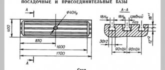
| Dimensions of the working surface of a horizontal table, mm | 250 x 630 |
| Dimensions of the working surface of the vertical table, mm | 160 x 500 |
| Distance from the axis of the horizontal spindle to the table during manual movement, mm | 60..360 |
| Desktop | |
| Maximum load on the table (center), kg | 140 |
| Number of T-slots Dimensions of T-slots | 3 |
| Maximum longitudinal movement of the table (si X), mm | 250 |
| Maximum lateral movement of the vertical head, mechanical (along Y), mm | 300 |
| Maximum vertical movement of the table (si Z), mm | 200 |
| Movement of the table by one dial division (longitudinal, transverse, vertical), mm | 0.02 |
| Speed of rapid longitudinal movement of the table (si X), mm/min | 800 |
| Speed of fast transverse stroke of the head (in Y direction), mm/min | 800 |
| Speed of rapid vertical movement of the table (si Z), mm/min | 800 |
| Number of table feed stages | 9 |
| The number of stages of working feeds of the spindle head | 9 |
| Limits of longitudinal working feeds of the table (si X), mm/min | 10..400 |
| Limits of transverse working feeds of the spindle head (in Y direction), mm/min | 10..400 |
| Limits of vertical working feeds of the table (si Z), mm/min | 10..400 |
| Maximum force allowed for longitudinal feed (along the X axis), (kgf) | 316 |
| Maximum force allowed for cross feed (along Y axis), (kgf) | 572 |
| The greatest force allowed for vertical feed (along the Z axis), (kgf) | 498 |
| Horizontal spindle | |
| Horizontal spindle rotation speed, rpm | 45..2000 |
| Number of horizontal spindle speeds | 12 |
| Inner cone of horizontal spindle. | Morse 4 |
| Diameter of mandrels, mm | |
| Horizontal spindle hole diameter, mm | |
| Diameter of the front bearing of the horizontal spindle, mm | |
| Spindle braking | There is |
| Spindle overload protection (clutch) | There is |
| Drilling and milling rotary head | |
| Spindle rotation speed of drilling and milling rotary head, rpm | 90..4000 |
| Number of spindle speeds of drilling and milling rotary head | 12 |
| Maximum displacement of the sleeve (quill) of the vertical spindle, mm | 60 |
| Mechanical feed of the spindle of the drilling and milling rotary head, mm/rev | 0,05 |
| Distance from the end of the spindle of the drilling and milling head to the table, mm | 335 |
| Distance from the spindle axis of the drilling and milling head to the bed guides (overhang), mm | |
| The inner cone of the spindle of the drilling and milling head. | Morse 2 |
| Milling and boring rotary head | |
| Spindle rotation speed of milling and boring rotary head, rpm | 45..2000 |
| Number of spindle speeds of milling and boring rotary head | 12 |
| Distance from the end of the spindle of the milling and boring head to the table, mm | 330 |
| Distance from the spindle axis of the milling and boring head to the bed guides (overhang), mm | |
| Angle of rotation of the milling and boring head in the vertical plane, mm | ±90 |
| The inner cone of the spindle of the milling and boring rotary head. | Morse 4 |
| Drive unit | |
| Number of electric motors on the machine | 2 |
| Main motion drive electric motor, kW | 2,2 |
| Coolant pump electric motor, kW | 0,12 |
| Dimensions and weight of the machine | |
| Machine dimensions (length width height), mm | 1400 x 1000 x 1720 |
| Machine weight, kg | 930 |
Bibliography:
High precision specialized milling machine VM130V. Operating manual VM130V 61.00.000, 1977
Avrutin S.V. Fundamentals of Milling, 1962
Avrutin S.V. Milling, 1963
Acherkan N.S. Metal-cutting machines, Volume 1, 1965
Barbashov F.A. Milling business 1973, p.141
Barbashov F.A. Milling work (Vocational education), 1986
Blumberg V.A. Milling machine handbook, 1984
Grigoriev S.P. Practice of coordinate boring and milling work, 1980
Kopylov R.B. Working on milling machines, 1971
Kosovsky V.L. Handbook of a young milling operator, 1992, p. 180
Kuvshinsky V.V. Milling, 1977
Nichkov A.G. Milling machines (Machinist's Library), 1977
Pikus M.Yu. A mechanic's guide to repairing metal-cutting machines, 1987
Plotitsyn V.G. Calculations of settings and adjustments of milling machines, 1969
Plotitsyn V.G. Setting up milling machines, 1975
Ryabov S.A. Modern milling machines and their equipment, 2006
Skhirtladze A.G., Novikov V.Yu. Technological equipment for machine-building industries, 1980
Tepinkichiev V.K. Metal cutting machines, 1973
Chernov N.N. Metal cutting machines, 1988
Frenkel S.Sh. Handbook of a young milling operator (3rd ed.) (Vocational education), 1978
Related Links. Additional Information
Home About the company News Articles Price list Contacts Reference information Download passport Interesting video KPO woodworking machines Manufacturers
Functional purpose
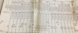
KM1 - connects 380 V voltage to the main motion drive M1 and the cooling pump motor M2; KM2, KM3 - connect 380 V voltage to the feed drive M3; KM4, KM5 - connect 380 V voltage to the motor of the tool fastening mechanism; K2 - turns on dynamic spindle braking; K3 - turns on the high speed of the feed drive and pulse activation of the main movement drive when switching spindle speeds; K5 - prepares the circuit for turning on the main movement drive after clamping the tool: KT1 - sets the spindle rotation time after turning it off before turning on the braking. KT2 — sets the spindle braking time; QF1 - input switch; QS2 - cooling pump switch; SQ3 - switch for pulse activation of the feed drive when switching speeds; SQ5, SQ7 - forward-backward and up-down table drive switch; SQ6, SQ8 — table drive switch “left-right”; SQ10 - switch for blocking the main movement and feeds when clamping a tool.
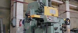
Machine Features
The device is equipped with a fairly powerful engine, which allows it to be equipped with cutting tools made of high-speed steel. The milling unit can be used on production lines that include a large number of devices.
The unit operates in both automatic and semi-automatic modes when setting up its main components.
The popularity of the machine in small enterprises is due to the ease of its operation. The device has mechanisms that can be easily adjusted if necessary. This allows the device to be used in harsh conditions. VM127 is easy to use and can be quickly repaired by any qualified technician.
Among the features of the machine are:
- the equipment of the device is automatically lubricated;
- reliability of the unit in difficult operating conditions;
- the presence of a servo-control feed drive with feedback;
- the ability to equip the device with a digital display device;
- the ability to perform milling under different conditions due to smooth control of feed speed and powerful drive;
- functioning of the lubrication system for the apparatus elements, operating in semi-automatic mode.
The device has mechanisms that significantly simplify the process of its use. This is ensured by the following elements:
- automatic feeding of longitudinal intermittent type;
- overload protection clutch;
- feed stops that turn off the working elements of the unit;
- feed activation blocking system;
- blocking of manual and mechanical feeds;
- system that brakes the spindle.
Tool clamp
To clamp the tool, you need to set the SA3 toggle switch (on the side panel) to the “Clamp” position and hold it with your hand. In this case, the KM4 starter is triggered, which supplies voltage to the motor of the tool clamping mechanism M4. The tool is being clamped. The clicking of the clutch in the clamping mechanism indicates the end of the tool clamping. The SQ10 microswitch with its contacts turns on the K5.1 starter, which becomes self-powered, turns off the M4 motor and prepares the spindle motor start circuit.
Unclamping the tool: set toggle switch SA3 to the “Unclamping” position and hold it with your hand. In this case, the KM5.1 starters are triggered. Starter KM5.3. supplies voltage to the M4 motor. The tool is spinning out. The end of the tool spin is controlled visually. Note: To avoid injury when opening the tool, the spindle start is blocked by the closing contacts K5. When the spindle is rotating, the opening of the tool is blocked by the opening contacts K5 in the M4 motor switching circuit. When clamping and unclenching the tool, in order to prevent the spindle from turning, it is necessary to set a low spindle speed (not higher than 400rpm)
Electric feed drive
The electric feed drive is an electromechanical system. Turning the feed on and off is carried out using handles that have three. fixed positions, as well as switches SQ6, SQ8 for longitudinal; SQ5, SQ7 for vertical or cross feed.
The fast feed stroke occurs when the SB9 button is pressed, the short circuit starter and the high speed electromagnet UA are turned on. On the machine, an electrical lock prevents the possibility of simultaneous activation of longitudinal and transverse or vertical feed.
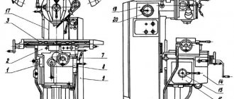
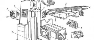
List and location of controls, passport
The most important controls are located at the front of the unit, as well as on the side panel from the swivel head and directly on the sides of the base.
To adjust the feed, there are knobs located directly in front of the master, slightly below the table surface. Here are located:
- a flywheel that moves the tool table;
- handle for moving the table vertically;
- lever to turn off movement along;
- control mode switch.
In addition, the equipment control system includes:
- "Start" button;
- duplicate spindle head stop button;
- table clamps;
- manual movement handles;
- flywheel for extending the spindle sleeve.
On the side of the frame there is a feed switch, as well as start and stop buttons for all main components.
Adjusting the spindle braking circuit
The braking circuit is adjusted after replacing or repairing the time relay KT1, KT2, as well as in the case when the timing characteristics of the braking circuit do not correspond to those specified in paragraph 7.6.5.
To make adjustments, you must: supply power to the machine, turn on the spindle
Simultaneously with the spindle switch, turn on the stopwatch and stop it when K2 is triggered. If the recorded time exceeds I sec., turn the time relay regulator KT1 clockwise. Repeat turning the spindle on and off, ensuring that the K2 starter turns on after 1 second. If the K2 starter operates in less than 1 sec. after turning off the spindle, then turn the relay regulator KT1 counterclockwise. Adjustment of relay KT2 is carried out similarly to KT1. Turn off the machine spindle while pressing the SB4 button, start the stopwatch and stop it after stopping the spindle. The recorded time should not be more than 6 seconds.
Electrical equipment
The electrical equipment of the VM127 machine can be divided into the following three parts: power, control and power module.
Power section
This component of the electrical circuit is represented by the power circuits of the main and auxiliary electric motors (M1, M2 and M3) and includes the following elements:
- Starter contactors.
- Safety inserts.
- Thermal relays.
- Reverse elements.
Thanks to these parts, the functionality of all drive systems and the required functionality of the equipment is ensured.
Control part
The control part of the electrics includes switching elements (time relays) with a group of low-current contacts that switch the operating modes of various components. This also includes protective components (fuses and inductors).
Note! Switching diagrams for machine equipment components are given in the tables. Using them as a guide, you can select the required operating mode
Using them as a guide, you can select the required operating mode.
Supply system
Electrical equipment power supply circuits provide:
- Converts AC voltage to DC potential needed to power the relay.
- Transformation of 220 Volt voltage to the level required for the lighting device (light bulb).
They include a diode bridge, switches, as well as fuses and a step-down transformer.