Design and its specifics
The structural parts of the mechanism provide functionality and rigidity. Features of the connection of nodes determine the efficiency of work.
Trunk and earrings
It is possible to move the trunk in the guides of the frame. And the earrings can be moved in the trunk and also secured. Rearranging earrings from other equipment is not allowed, as they are mounted individually for each bearing. In case of breakdown, they are made independently.
The gap is adjusted using a screw and nut. The oil supply passes through a wire from the bearing. The temperature of the rotating part should not exceed 55 degrees during operation.
Gearbox
The gearbox is located in the frame housing and is visible through the window on the right. The spindle is a shaft with three supports, the third of which is connected to the tail. Adjustment occurs by removing the cover, loosening the nut and running in the spindle, reducing the gaps.
Lubrication occurs with a pump with a capacity of up to 2 liters per minute. It enters the nodes using tubes, and is sprayed onto the separated elements from the holes.
Gearbox
The operation of the switch box makes it possible to choose the optimal operating speed, but without going through all the intermediate steps. In a milling machine it is implemented using a device consisting of a rack, a handle, a fork, a shift disk, bevel gears, and a gear wheel.
Matching speeds is achieved by setting a certain ratio of gears. Lubrication occurs by supplying oil from the frame.
Gearbox
Necessary for moving the table, console and slide. Having received information from the control panel, the signal is sent to the output shaft and couplings. It is fed to the cam bushing, which compresses the springs that drive the gear. The supply to the nuts and discs changes depending on which couplings and the end of the bushing are used. In turn, this determines the movement of the wheel and the transmission of rotation.
Overall dimensions of the workspace
Form factor smaller than model 83. Table and spindle phases are taken into account. The standard scheme indicates that parameters are given that are at least 128.57 centimeters in length. The circular element determines the dimensions (it is worth taking into account the rotation by 45 degrees). The diagonal is 101 centimeters, not taking into account the rotation angle.
Advantages and disadvantages
The developers took into account the comments of milling operators on previous models and the wishes of production workers to have a highly productive and at the same time accurate machine. Model 6M82 has a rigid trapezoidal frame and a powerful engine. The machine is designed to work with heavy loads, milling at high speed with carbide plates. Its positive differences from analogues:
- increased spindle speed and machining cleanliness;
- movement of the table relative to the tool simultaneously along 3 axes;
- setting for automatic cycles;
- the use of devices and accessories increases the technological capabilities of the machine.
The weak point of the machine is the electromagnetic clutch, which, when started, must ensure a quick start of movement. It fails before other nodes. Small chips fall under the table and clog the lubrication holes in the longitudinal movement and rotation guides of the table.
Important! When rotating centers with a dividing head are installed on the table, a tooth can be cut on a 6M82 milling machine. The rotary table allows the production of helical gears.. https://www.youtube.com/embed/Z42Df3SbmyE
Analogs
The main analogues of the 6Р82Ш machine include the following units:
- 6Р83Ш – widely-universal cantilever milling machine 400x1600;
- 6Р83 – cantilever milling machine 400x1600;
- 6R82G – horizontal cantilever milling machine 320x1250.
The entire 6P series was put into production by the Gorky plant in 1972, and machines of this series are still produced and are popular because they are reliable.
The 6Р82 Ш cantilever milling machine is successfully used for the widest range of milling work. Workpieces weighing up to 1 ton can be milled on both sides of the machine, which is another advantage and useful design feature. It is also possible to carry out simple boring operations using this equipment.
In terms of size and performance, the unit is successfully used not only in small-scale and individual production, but also in some large repair enterprises, especially since the machine itself is very reliable and has been working without interruptions for more than one year. If the main components are severely worn, they are replaced and the machine is back in service for a long time.
Purpose of the metal cutting machine 6N81
For milling the planes of small parts of various configurations made of steel, cast iron and non-ferrous metals using cylindrical, disk, face, shaped and other cutters. The wide technical characteristics of the machine allow the use of high-speed cutting tools
Technical characteristics of the machine 6N81
We offer to buy new or overhauled analogues of equipment such as Horizontal console-milling machine 6N81 at a competitive price. You can select the appropriate model yourself on our website in the CATALOG section, or by consulting the sales department of our company.
The sale of analogues of the machine model 6N81 is made with 100% prepayment if the equipment is in stock and 50% prepayment when the machine is put into production at the manufacturer and payment of the remaining 50% after notification of its readiness for shipment. Another jointly agreed upon payment procedure is possible.
The warranty for products similar to the product - Horizontal cantilever milling machine 6N81 is:
- new machines - 12 months,
- after major repairs - 6-12 months.
Manufacturers reserve the right to change the standard configuration and place of production of equipment without notice!
We draw your attention to the fact that the prices indicated on our website are not a public offer, and check the cost of the equipment with our sales managers of machine tools and forging equipment!
If you need to buy a horizontal console-milling machine 6N81, call:
Features and Benefits
The “6P82” series of machines has the following capabilities and operating mechanisms:
- quick-change device fastener;
- wide table feed range;
- mechanism for slowing down or accelerating the feed;
- Feed slowdown during automatic operation cycle;
- the ability to perform work in an automatic cycle;
- automatic and semi-automatic lubrication of components;
- the potential possibility of supplementing the machine with digital devices (display system, operational control mechanism, and so on).
The 6P82 milling machine is one of the popular metalworking machines
The advantages of the entire series of 6P82 milling machines are as follows:
- universal purpose (scope of application);
- there is a copy of the push-button-handle type control (the main control panel is located in front of the device, and its copy is on the left side of the machine);
- spindle start and stop system;
- the ability to start the high speed of the machine exclusively using a push-button control panel;
- the ability to control the movement of the table using handles;
- the ability to change the feed speed using a special handle mechanism;
- DC braking capability;
- The table of machines in this series can easily be rotated around a vertical axis at an angle of up to 45 degrees, with the ability to perform this manipulation in both directions.
to menu
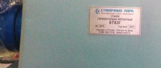
Characteristics and designations
The device contains a special passport, which contains decoding data for the alphanumeric index of the machine and its technical characteristics. The index passport of the “6P82” machine and the entire series of this device deciphers the alphanumeric designations of the “6P82” model as follows: where the number is the series of the milling machine, the letter “P” denotes the modification of the machine.
The number “8” means that this is a cantilever-horizontal milling machine, the number “2” is the standard size of the device (the size of its table). The technical data sheet describes in detail the characteristics of the device, the basic of which are as follows:
- working surface size - 1250x320 millimeters;
- accuracy class "N";
- maximum longitudinal movement of the device table is 850 mm, transverse movement is 250 mm; vertical - 400 mm.
Widely versatile horizontal milling machine
In addition, the device passport contains information about the purpose of the device. In general, the passport of this series of milling machines, like the passport of any other similar mechanism, describes in detail the operating rules of the device and its technical and physical features. Along with the operational passport there should always be a warranty card and data on the delivery set.
to menu
Processing parts on a milling machine (video)
data-full-width-responsive=”true” data-ad-client=”ca-pub-8514915293567855″data-ad-slot=”8040443333″>
Technical characteristics of machines models 6Р82Ш
| Parameter name | 6Р82Ш | 6Р83Ш |
| Basic machine parameters | ||
| Accuracy class according to GOST 8-82 | P | P |
| Dimensions of the working surface of the table (length x width), mm | 1250 x 320 | 1600 x 400 |
| The smallest and largest distance from the end of the spindle to the table, mm | 30..450 | 30..450 |
| Distance from the spindle axis to the trunk, mm | 155 | 190 |
| Distance from the end of the rotary head spindle to the table, mm | 35..535 | 70..570 |
| Distance from the axis of the rotary head spindle to the frame guides (extent), mm | 260..820 | 250..900 |
| Desktop | ||
| Maximum table movement longitudinal mechanical/manual, mm | 800/ 800 | 1000/ 1000 |
| Maximum table movement transverse mechanical/manual, mm | 240/ 250 | 300/ 320 |
| Maximum table movement vertical mechanical/manual, mm | 410/ 420 | 410/ 420 |
| Maximum load on the table (center), kg | 250 | 300 |
| Number of T-slots Dimensions of T-slots | 3 | 3 |
| Movement of the table by one dial division (longitudinal, transverse, vertical), mm | 0,05 | 0,05 |
| Table movement per one revolution of the dial, longitudinal and transverse, mm | 6 | 6 |
| Movement of the table per one revolution of the dial, vertical, mm | 2 | 2 |
| Rapid table travel longitudinal/transverse/vertical, mm/min | 3/ 3/ 1 | 3/ 3/ 1 |
| Number of table feed stages | 18 | 18 |
| Working feed limits. Longitudinal and transverse, mm/min | 25…1250 | 25…1250 |
| Working feed limits. Vertical, mm/min | 8,3…416,6 | 8,3…416,6 |
| Cutting force of longitudinal, transverse, vertical feeds, N | 15,0/ 12,0/ 5,0 | 20,0/ 12,0/ 8,0 |
| Spindle | ||
| Spindle rotation speed of rotary and overhead heads, rpm | 50..1600 | 50..1600 |
| Number of spindle speeds | 11 | 11 |
| Spindle speed, rpm | 31,5..1600 | 31,5..1600 |
| Number of spindle speeds | 18 | 18 |
| Spindle quill movement, mm | 80 | 80 |
| Movement of the spindle quill by one dial division, mm | 0,1 | 0,1 |
| Movement of the spindle quill per one revolution of the dial, mm | 6 | 6 |
| Rotation of the spindle head to/from the bed, degrees | 45 | 90 |
| Rotation of the spindle head in the longitudinal plane, degrees | 360 | 360 |
| Rotation of the spindle head in the longitudinal plane, degrees | 360 | 360 |
| Maximum torque on the spindle, N.m | 1070 | 1430 |
| Sketch of the end of a horizontal spindle according to GOST 836-72 | 3 | 3 |
| Sketch of the end of the spindle of the rotary head according to GOST 836-72 | 4 | 4 |
| Sketch of the end of the spindle of the overhead head according to GOST 836-72 | 4 | 4 |
| Spindle taper | 50 | 50 |
| Permissible cutter diameter for roughing. Horizontal/vertical spindle, mm | 160/ 100 | 200/ 100 |
| Machine mechanics | ||
| Feed stops (longitudinal, transverse, vertical) | There is | There is |
| Blocking manual and mechanical feed (longitudinal, transverse, vertical) | There is | There is |
| Blocking separate feed switching | There is | There is |
| Automatic intermittent feed Longitudinal | There is | There is |
| Automatic intermittent feed Cross and vertical | No | No |
| Spindle braking | There is | There is |
| Overload protection (clutch) | There is | There is |
| Drive and electrical equipment | ||
| Number of electric motors on the machine | 4 | 4 |
| Main motion drive electric motor, kW | 7,5 | 10 |
| Electric motor for rotary head spindle drive, kW | 2,2 | 3,0 |
| Feed drive electric motor, kW | 2,2 | 3,0 |
| Electric coolant pump, kW | 0,125 | 0,125 |
| Dimensions and weight of the machine | ||
| Machine dimensions (length x width x height), mm | 2470 x 1850 x 1950 | 2680 x 2260 x 2040 |
| Machine weight, kg | 3300 | 4500 |
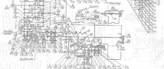
Kinematic diagram of the machine model 6N81
⇐ PreviousPage 4 of 8Next ⇒
Cutting movement. From a flange electric motor with a power of 5.8 kW, the movement is transmitted by a semi-rigid coupling to shaft I through the gearbox.
rpm
Feed movement
The console mechanisms receive rotation from an electric motor N = 1.7 kW, directly connected by a semi-rigid coupling to the first shaft VIII of the feed box.
The general formula for, for example, longitudinal feed can be written
Speed of fast table movements
mm/min
those. bypassing the feed box.
Purpose and classification of dividing heads
Dividing devices and heads are used when working on metal-cutting machines: milling, drilling, boring, planing, sharpening, grinding, etc. Using dividing heads, the following is performed: milling simple planes and grooves, cutting cylindrical gears with straight and helical teeth, worms, worm gears wheels, milling cams, applying precise divisions on scales and dials. Dividing heads are also widely used in the manufacture and sharpening of cutting tools.
Simple dividing heads are used for direct (direct) division. The dividing mechanism, as a rule, consists of a dividing disk having precisely executed grooves or holes into which a locking pin or latch fits. The number of holes or grooves usually made on the disk is 12, 18, 24 or 36. The number of grooves on the disk determines the limit of the dividing head
Universal dividing heads.
The main features of UDG include the following:
1) they allow you to install the spindle together with the workpiece at an angle in a vertical plane;
2) ensure the division of the workpiece circumference into any number of parts;
3) make it possible to mill helical and spiral grooves due to the presence of a device for connecting the machine drive.
Division methods
On different designs of dividing heads, division {circles is performed in different ways: by direct division; simple division; combined, universal, differential and wide-range.
Direct division, or direct, is performed on simple and universal heads when dividing the workpiece circumference into a small number of parts from 2 to 36 when milling flats, etc. In the case of working with UDG, the worm is disengaged from the worm wheel and the spindle is rotated directly by hand. The area of use of direct division is very limited.
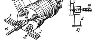
Simple division method. The kinematic diagram of the UDG when configured using the simple division method is shown in the figure. Rotation of the spindle is transmitted from handle 1 through groups of ribbed wheels and worm gear 7-8. The position of the handle when turned to the required angle fixes the dividing disk 2.
The gear ratio of all gears except the worm gear (and replacement wheels) is 1.
The simple division method is used in cases where the gear ratio of the chain between the shaft with the handle and the head spindle can be expressed as a simple fraction. If Z is the number of equal parts into which the circle must be divided, then the amount of periodic rotation of the head spindle will be 1/Z turn. To do this, handle 1 must be rotated relative to the fixed disk 2 by nr revolutions
(1)
By denoting and solving equation (1), we find the required number of handle revolutions.
(2)
The value N is called the characteristic of the dividing head. Most often N = 40. The resulting value nр is expressed as a simple fraction
,
in which B is equal to the number of holes on one of the circles of the dividing disk; A – the number of holes in the same circle to which you need to turn the handle.
Example: (6 – the number of full turns of the handle; 21 – the number of holes in the corresponding circle of the dial; 14 – the number of intervals by which the handle needs to be turned after 6 full turns).
Method of differential division. It is used in cases where it is not possible to select a disk with the required number of holes using simple division. The essence of differential division is as follows. A fictitious number of parts ZФ is selected by which it is necessary to divide, close to the given Z, and satisfying the simple division method. If you perform a simple division, the spindle will rotate 1/Zph instead of 1/Z turn. To compensate for the resulting difference, the spindle is given an additional rotation equal to 1/Z - 1/Zph. If this difference is positive, then an additional turn is made in the same direction as the main one. If negative, then in the opposite direction.
Thus, handle 1 must make a main rotation in order to divide into Zph parts, and an additional one to compensate for the specified difference.
This is achieved by slowly rotating disk 2 by the amount of additional rotation of the handle. Rotation of the disk is transmitted from the dividing head through replaceable wheels a-b, c-d, a conical pair 9-10 and gear wheels 3-4. Calculation of the settings is reduced to:
1) to the definition of nр for turning to Zф;
2) to determine the gear ratio of replaceable gears a-c, c-d.
To turn the spindle by 1/Z and 1/Zph turns, you need to turn the handle accordingly:
, about.; , about. (3)
Milling of helical grooves located evenly around the circumference is carried out as follows. The workpiece installed at the centers of the dividing head and tailstock together with the table is rotated through an angle β equal to the angle of inclination of the helix of the groove.
As a result, the middle plane of the disk cutter coincides with the direction of the groove. The workpiece is given continuous rotation, and the table is given longitudinal feed along the groove line. The rotation of the UDG spindle is carried out from the lead screw of the longitudinal feed of the table along a chain of replaceable gears a1 – b1; c1 –
d1
,
then through pairs 9-10, 3-4 and disk 2 to handle 1, then to gears 5-6 and 7-8. For one revolution of the spindle, the table must move by the pitch of the helical line of the groove tP.
The kinematic balance equation will take the form:
Here tв is the lead screw pitch.
Considering that
we obtain the equation for tuning the kinematic chain:
.
In practice, the helix of a groove is specified not by the pitch tр, but by the angle of inclination β (or the angle of elevation of the helix Ψ = 90 - β) and the diameter d. In this case, the step is determined by the formula:
.
Limless dividing heads differ from dial ones in that they do not have dividing disks; the handle rotates one full turn and is fixed in a constant position on a stationary disk. The amount of rotation of the spindle is set by interchangeable wheels a2-b2, c2-d2. When simply dividing into Z parts, the kinematic balance equation takes the form:
,
and the gear ratio of the tuning link:
,
where N = Z3/Z4 – head characteristic. To divide into equal and unequal parts with increased accuracy (0.25′), optical dividing heads are used. The division method consists of simply turning the spindle by pre-calculated angles, measured through the microscope eyepiece on the disk scale.
⇐ Previous4Next ⇒
Recommended pages:
Use the site search:
Specifications
| Characteristic | Meaning |
| Basic machine parameters | |
| Accuracy class according to GOST 8-82 | P |
| Dimensions of the working surface of the table (length x width), mm | 1250 x 320 |
| The smallest and largest distance from the axis of the horizontal spindle to the table, mm | 30..450 |
| Distance from the axis of the horizontal spindle to the trunk, mm | 155 |
| Distance from the end of the rotary head spindle to the table, mm | 125..545 |
| Distance from the axis of the rotary head spindle to the frame guides (extent), mm | 260..820 |
| Desktop | |
| Maximum table movement longitudinal/transverse/vertical, mm | 800/ 320/ 420 |
| Maximum load on the table (center), kg | 400 |
| Number of T-slots Dimensions of T-slots | 3 |
| Movement of the table by one dial division (longitudinal, transverse, vertical), mm | 0,05 |
| Table movement per one revolution of the dial, longitudinal and transverse, mm | 6 |
| Movement of the table per one revolution of the dial, vertical, mm | 2 |
| Rapid table travel longitudinal/transverse/vertical, m/min | 4/ 4/ 1,3 |
| Number of table feed stages | 22 |
| Table working feed limits. Longitudinal and transverse, mm/min | 12,5…1600 |
| Table working feed limits. Vertical, mm/min | 4,1…530 |
| Cutting force of longitudinal, transverse, vertical feeds, N | 15,0/ 12,0/ 5,0 |
| Spindle | |
| Spindle rotation speed of rotary and overhead heads, rpm | 50..1600 |
| Number of spindle speeds | 11 |
| Horizontal spindle rotation speed, rpm | 31,5..1600 |
| Number of horizontal spindle speeds | 18 |
| Movement of the spindle quill (sleeve), mm | 80 |
| Movement of the spindle quill by one dial division, mm | 0,1 |
| Movement of the spindle quill per one revolution of the dial, mm | 6 |
| Rotation of the spindle head to/from the bed, degrees | 45 |
| Rotation of the spindle head in the longitudinal plane, degrees | 360 |
| Rotation of the spindle head in the longitudinal plane, degrees | 360 |
| The end of the horizontal spindle according to GOST 24644-81 (cone according to GOST 15945-82) | 50 row4, version 6 |
| Sketch of the end of the spindle of the rotary and overhead head according to GOST 24644-81 | 40 row 3, version 5 |
| Permissible cutter diameter for roughing. Horizontal/vertical spindle, mm | 250/ 75 |
| Machine mechanics | |
| Feed stops (longitudinal, transverse, vertical) | There is |
| Blocking manual and mechanical feed (longitudinal, transverse, vertical) | There is |
| Blocking separate feed switching | There is |
| Automatic intermittent feed Longitudinal | There is |
| Automatic intermittent feed Cross and vertical | No |
| Spindle braking | There is |
| Overload protection (clutch) | There is |
| Drive and electrical equipment | |
| Number of electric motors on the machine | 5 |
| Main motion drive electric motor M1, kW | 7,5 |
| Electric motor for rotary head spindle drive M2, kW | 3 |
| Coolant pump electric motor M3, kW | 0,125 |
| Electric motor for table feed drive M4, kW | 2,2 |
| Tool clamp drive electric motor, kW | 0,18 |
| Total power of all electric motors on the machine, kW | 13,87 |
| Dimensions and weight of the machine | |
| Machine dimensions (length x width x height), mm | 2280 x 1965 x 1970 |
| Machine weight, kg | 3550 |
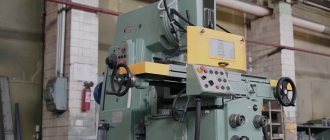
Model 6N82
The 6N82 milling machine can easily be called one of the most popular units in the territory of the former USSR, which has been used by more than one generation of craftsmen. Interestingly, this model was successfully exported outside the country of origin, which hints at its remarkable technological advantages.
This milling machine is designed for high-quality processing of medium and small metal structures. Simple to operate and surprisingly reliable, 6N82 milling machines set the standard for versatility. They do an excellent job with cast iron and steel, as well as with non-ferrous metals and products made from durable alloys.
A separate advantage of the unit is that it can be used to process plastic products. By installing such equipment in your workshop, you can be sure that the unit will perform most of the tasks assigned to it at a high level, ensuring the highest possible precision in processing the workpiece.
This is greatly facilitated by the rigidity of the design of the 6N82 milling machine. We also note that the unit is equipped with a powerful electric motor, which makes it possible to perform high-quality processing of parts using cutters with plates made of high-speed steel and super-hard alloys. All this makes the 6N82 an indispensable assistant for a qualified craftsman who needs equipment for a wide range of applications.
Let us mention the key technical parameters of the 6N82 milling machine:
- Electric motor power – 5.5 kW;
- The power of the electric drive of the desktop is 1.5 kW;
- Dimensions - 2135x1865x1695 mm;
- Weight – 2360 kg;
- Limits of movement of the working table in the longitudinal/transverse/vertical direction – 850/250/400 mm;
- Range of distances from the spindle to the table – 50-410 mm;
- The maximum extension of the spindle sleeve is 60 mm;
- Maximum spindle speed – 2000 rpm;
- Compliance with GOST 30064-93.
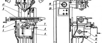
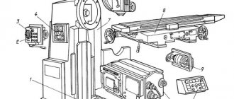
Location of controls for the 6M12P cantilever milling machine
Location of controls for the 6M12P cantilever milling machine
Location of controls for the 6M12P cantilever milling machine
Location of controls for the 6M12P cantilever milling machine
List of components of the 6M12P cantilever milling machine
- bed
- Swivel head
- Gearbox
- Gearbox
- Switch box
- Console
- Table and slide
- Electrical equipment
List of controls for the 6M12P cantilever milling machine
- Cooling intensity control valve
- Handwheel for manual longitudinal movement of the table
- Cams for limiting the longitudinal travel of the table in extreme positions or reversing the table in semi-automatic and automatic cycles
- Cams for switching the table from feed to high speed or from high speed to feed
- Switch for automatic cycle or manual control of the machine
- Spindle start button
- Stop button
- "Quick" button
- Table lubrication hand pump handle
- Handle for switching on vertical or transverse table feed
- Console clamp handle on bed guides
- Handwheel for manual transverse movement of the table
- Slide clamp handle on console guides
- Table control switch: automatic cycle - manual control - round table operation
- Hexagon rotation of milling head
- Table Clamp Screws on the Slide
- Spindle sleeve movement flywheel
- Light switch "On - Off"
- Stop spindle button
- Spindle start button
- Handle and dial for switching spindle speeds
- Spindle pulse button
- "Quick table" button
- Input switch "On - Off"
- Cooling Pump On/Off Switch
- Spindle rotation direction switch “Left - Right”
- Control handle for longitudinal movement of the table
- Console lift handle
- Mushroom and dial for switching table feeds
- Table cross travel limiting cams
- Spindle sleeve clamp handle
- Cams for limiting the vertical movement of the table
- Feed shift mechanism locking button
- Rotary milling head clamp nuts
Design features
A unit of normal accuracy class with a rotary table that can move in three directions. The main spindle never changes position in the device.
Components
The basis of the unit is the bed. It has a rigid casting, and special ribs make the structure more rigid. On top of the frame there are guides along which the easel trunk moves. One or more earrings are mounted to it. A container is mounted separately where the coolant is collected.
The unit table performs rapid movements along three axes. All working movements of both the machine and the spindle mechanism are performed by two electric motors, which can be switched on independently of each other.
Technical parameters of the spindle assembly:
- 18 different speeds;
- the spindle rotates at a frequency of up to 1600 rpm;
- 45 cone.
The equipment has a total of 16 feed stages. The machine is protected from overload by a ball pair, which brakes the spindle using a clutch. There is a locking mechanism to brake the vertical and transverse mechanical feed. The gearbox and gearbox are mounted in a common unit. There is a separate reverse box.
Controls
All handles, switches, buttons are located at a convenient height next to the controlled mechanisms. Main controls: spindle start, feed, general stop. Directly next to these controls are located:
- selector and speed shift knob;
- to rotate the trunk, a special square is moved;
- “spindle push” button;
- handle for turning on longitudinal, vertical and transverse feed;
- cooling pump switch;
- screws to secure the slide from rotation.
A special curved handle is used to raise and lower the console from the table. There is also a lever to enable rapid travel in any direction.
Electrical equipment
The electrical equipment of the milling machine is represented by a power supply network with a voltage of 380 V. The alternating current frequency is 50 Hertz. There are two control networks, one supplying 110V AC and the other supplying 65V DC.
The machine is equipped with light devices up to 24 V. In this case, the sum of simultaneously operating electric motors of the machine cannot exceed 20 Amperes. At the same time, up to 65 Amperes are observed in protective devices, for example, sensors, automatic power and shutdown regulators, fuses of structural components of the mechanism.
Read with this
- Technical characteristics, design and diagrams of the horizontal milling machine model 6р82
- Characteristics of vertical drilling machine 2n118
- Detailed review of the vertical cantilever milling machine 6р11
- Review of the universal milling machine 676, description, passport
- Surface grinding machine 3g71
- Screw-cutting lathe 1m61, passport, characteristics, diagram, manual
- Description of the parameters of the horizontal milling machine 6р82
- Cylindrical grinding machine 3m151
- Technical characteristics of screw-cutting lathe 1k625
- Lathe 1d601 technical specifications
Modifications and foreign models
There are both Russian modifications of the 6P81 unit, as well as imported analogues with similar characteristics. Domestic machines:
- 6Р81Ш is a highly versatile machine.
- 6k82sh is another version of a highly versatile machine with a special spindle head that can be rotated horizontally and vertically.
- 6N81 – horizontal, vertical – 6N11.
Consoleless milling machines have a spindle that moves strictly vertically.
- X613A is a Chinese-made cantilever milling machine.
- X6132 – universal cantilever milling machines with a size of 1320x320.