Information about the manufacturer of the multi-spindle lathe 1B265
The manufacturer of 1B265 automatic multi-spindle lathes is the Kiev Machine Tool Plant .
Machine tools produced by the Kyiv Machine Tool Association (KSPO)
- 1A240
- six-spindle lathe Ø 40 - 1B240
- six-spindle lathe Ø 40 - 1B265
- multi-spindle lathe Ø 65 - 1340
— turret lathe with a vertical axis of the turret head Ø 40/ Ø 400 - KA-280
- universal screw-cutting lathe Ø 400
The history of the appearance of a multi-spindle vertical semi-automatic lathe
The appearance of multi-spindle vertical semi-automatic lathes was preceded by a rather long history.
The American Civil War (1861-1865), which created a labor shortage, required automation of production. Then the first automatic machine appeared. K. Vipil created an automatic machine for processing wood back in 1842, and in 1876 Chr. Spencer automated the lathe. His namesake, the English engineer S. Spencer, built his own automatic lathe back in 1860. The multi-spindle machine (in which a product automatically passes through a number of positions and at each of them is subjected to one or more processing operations) appeared in 1895. On the eve of the First World War, automated lathes appeared, on which the workpiece passes sequentially through six to eight positions, and at For each of them, the workpiece is subjected to different turning operations. This machine is known as Bullard's "Multomatic" (Fig. 1). Rice. 1. Bullard's "Multomatic"
Operating principle of the machine 1B265
In the rotary spindle drum, the processed bars or pipes, clamped in the spindles, rotate. Each of the spindles is served by a transverse slide and a central longitudinal slide.
At the end of processing, the supports are retracted, the spindle drum is rotated, and the spindles take a new position (position). The processed rods fall under the influence of other tools installed on the transverse supports and the edges of the longitudinal support, in accordance with the processing process.
Processing ends at the last position where the finished part is cut off.
In the same position, the rod moves out of the spindle to the required length, i.e. the rod is fed all the way to the end for the manufacture of a new part.
Thus, simultaneous processing of all rods or pipes fixed in the drum spindles is carried out. The processing time is the same for all positions. After each rotation of the spindle drum, one machined part is cut off.
When processing simple parts, it is possible to cut off two or more parts in one turn of the drum. On an eight-spindle machine this is achieved through double indexing, i.e. turning the spindle drum not by one, but by two positions (90°). The cutting positions are located nearby: UII and UIII and are served by a common double cutting support and a common mechanism for feeding and clamping rods. Additionally, another material stop lever stops.
In a six-spindle automatic machine for processing simple parts, cutting and subsequent feeding of the bar is carried out in diametrically opposite positions VI and III. To do this, a cutting support and additional mechanisms for feeding and clamping the bar and a material stop (version KA-395) are installed in position III.
In both cases, parts are processed in parallel in 2 threads, which significantly increases the productivity of the machine. It is also possible to produce 2 or several parts in one turn of the drum by feeding the rod onto 2 parts at once.
The processing method described above on 6 and 8 spindle machines allows processing at a small distance from the cutting tool to the spindle, which provides higher processing modes and also simplifies the cutting tool and equipment.
NOTE: the design of machines with double indexing or with feeding in two positions must be specifically specified when ordering the machine.
Devices and accessories that improve the technological capabilities of automatic and semi-automatic machines and are supplied for an additional fee
- Set of oriented spindle stop units
- Cross drilling device
- Device for milling from a longitudinal slide
- Cross slide milling device
- Set of units for bar feeding in two positions
- Set of magazine loading units for piece workpieces
- A set of units for changing the spindle speed when moving to the next position
- Drive devices with independent feed
- Device for supporting parts during cutting
- Device for finishing parts from the cutting side
- Device for crushing chips when machining from a transverse slide
- Vibrator for chip crushing
- Multi-spindle drilling head
- Device for boring internal shaped surfaces
- Device for turning internal grooves and chamfers from a longitudinal support
- Device for turning internal grooves and chamfers from a cross slide
- Device for boring and turning cones
- Device for switching on self-switching taps and threading heads
- Device for cutting parts without burr
- Device for mechanized loading of bars
- Device for automated loading of bars
- Multi-pass thread cutting device
- Device for boring the groove of the outer rings of bearings
- Device for rolling corrugations
- Device for milling splines and flats
- Device for flashing multi-faceted holes
- Rolling and rolling device
- Forced cutting tool change system
- Device for determining the degree of dullness of a cutting tool
- Device for crushing chips when processing parts from a longitudinal support
- Device for processing spherical surfaces
- Automatic dimensional adjustment system
- System for filtering coolant vapors
- Device for remote control of cutting tools
- Control system for special automatic and semi-automatic machines based on microprocessor technology
- Technological equipment sets of complexity groups A, B, C, D
- Loading and unloading devices of complexity groups A, B, C, D
Modifications of multi-spindle automatic machines (semi-automatic) 1B265
- 1B265-4K — Automatic four-spindle bar lathe of increased accuracy (P) according to GOST 8-77
- 1B265-6K — Automatic six-spindle bar lathe of increased accuracy
- 1B265-8K — Automatic eight-spindle bar lathe of increased accuracy
- 1B265P-4K — Semi-automatic six-spindle cartridge lathe with increased accuracy
- 1B265P-6K — Semi-automatic six-spindle cartridge lathe with increased accuracy
- 1B265P-8K — Semi-automatic six-spindle cartridge lathe with increased accuracy
Designations of multi-spindle automatic machines and semi-automatic machines:
- The first digit in the designation is the group: 1 - lathe group machine
- The second digit in the designation is a subgroup: 2 - multi-spindle automatic or semi-automatic
- Last number: bar processing diameter, for example: 16, 25, 40, 65, 90
- Letter in the designation: machine generation (series, etc.), for example: B.
- Letter in the designation: P - cartridge semi-automatic
- The last letter K means that this machine has increased accuracy according to GOST 8-82E
- Last number separated by a hyphen: number of spindles, for example: 4, 6, 8
Multi-spindle and semi-automatic machines. General information
Scheme of processing a part on a four-spindle machine
Scheme of processing a part on a multi-spindle machine
- Machine spindle block
- Spindles
- Blank parts
- I - spindle position: feed and clamping of the bar. Cutting a groove with a cross slide cutter
- II - spindle position: the cutter of the second transverse support processes the outer surface
- III - spindle position: a hole is drilled with a drill installed in the longitudinal support
- IV - spindle position: the finished part is cut off
The main unit of the machine, the spindle block, periodically rotates and the spindles take a new position. Each position of the spindle is given a name: 1st position, 2nd position, etc. At each position a specific operation is performed. A cutting tool is installed in the support against each spindle, carrying out an operation specific to a given position.
Let's say that we need to produce the part shown in Fig. b. In position I, the rod is fed all the way and clamped, and then a groove is cut with the cutter of the transverse support. After turning the block, the workpiece enters position II, where the outer surface is machined with the cutter of the second transverse support. The block is rotated again, and the part is in position III, where a hole is drilled with a drill installed in the longitudinal support. In position IV, the finished part is cut off.
Samples of parts processed on cartridge semi-automatic machines
Samples of parts processed on cartridge semi-automatic machines
A distinctive feature of multi-spindle and semi-automatic machines is the presence of several simultaneously operating spindles.
The variety of operations performed on machines makes it possible, in some cases, to process a complex part in one cycle, eliminating modification on other machines. The design feature of the machines is the original longitudinal support drive with a change in the working stroke without changing the fists, which greatly facilitates readjustment. A special setup drive speeds up setup and reduces physical labor.
On six-spindle machines, high processing productivity is achieved due to the simultaneous operation of all spindles and multi-tool setup. Six bars are processed simultaneously. The spindle drum periodically rotates 60°, and the spindles change their position (position), and, consequently, the cutting tool that processes the part. In the last position VI, the finished part is cut off and a rod is assembled for processing the next one.
Each position is served by transverse and longitudinal supports, and the last four positions are served by additional devices with feed independent from the other supports and devices. In addition, tool spindles can be installed in five positions (II, III, IV, V, VI), rotating tools (drills, reamers, taps, etc.) at a speed independent of the working spindles, which makes it possible to use various devices, requiring changes in cutting speed.
All transverse supports are table type and are controlled directly from replaceable knuckles. The feeds of the transverse and longitudinal calipers are infinitely adjustable.
The rigid design of these machines ensures consistently precise machining with high cutting performance. Numerous additional devices, such as a multi-faceted turning, multi-spindle drilling (head) and others, significantly expand the scope of application of these machines in the national economy.
The machine can be built into an automatic line.
Automatic control using electromagnetic clutches and a command device.
A screw conveyor is used to remove chips from the machine.
Machine capabilities that increase processing accuracy and ensure high economic efficiency:
- turning of cylinders and cones from a longitudinal support, grooves in holes at the ends, chambers in holes, spherical and curved surfaces
- drilling deep holes of small diameters, holes perpendicular to the axis of the part, several holes at the end of the part
- ensuring the required cutting speed with an axial tool regardless of the spindle speed
- hole reaming
- milling of grooves, flats on the end of a part, keyways, splines
- securing workpieces: jaw chucks, collet chucks, collet chucks, self-aligning piston chucks, special single-jaw chucks, multi-leaf chucks, rotary chucks, with workpiece re-edging
- cutting, milling, thread rolling
- processing the part from the cutting side
- support for long parts when cutting off
- wear control and automatic adjustment of cutting tools
Where are multi-spindle 3D milling machines used?
The scope of use of such machines is quite wide:
- Artistic production, which in turn is divided into:
- Promotional Products. Through the use of a special program for controlling machines, many advertisers have the opportunity to not simply produce logo engravings of their brands, but also to produce extensive advertising structures of a higher complexity.
- Furniture manufacturing. For furniture production, such machines are equipped with the functions of producing carved facades, curved cutting, and perfect fitting of each element. And this is not the whole set of functions that the machines are equipped with.
- Mechanical engineering. Automatic units help produce the most accurate components for various machines and mechanisms.
- Souvenir business. Despite the fact that such machines are used in almost all areas, they have found the greatest popularity in souvenir production. After all, it is often necessary to produce a huge number of different parts of various sizes, shapes and designs. When using manual machines, productivity remains extremely low, as the human factor takes its toll, slowing down the processing process significantly.
In addition to the listed use cases, you can also add the possibility of using such machines at home. Many people began to purchase machines to implement their hobby.
1B265-6K Landing and connecting bases of the machine
Landing and connecting bases of the machine 1B265-6K
Landing and connecting bases of the machine 1B265-6K. Spindle
Application of automatic longitudinal turning machines
Automatic longitudinal turning machines are used for the serial production of small-sized cylindrical parts of high precision from calibrated rods, shaped profiles and wire. Their productivity can reach several dozen finished parts per minute. The ranges of geometric dimensions of these products are usually: diameter - 1-60 mm, length - 5-300 mm, and quality characteristics - sixth to eighth quality in diameter and at least eighth quality in length. Typical examples of such products are shafts, bushings, axles, crossbars, collets, hollow cylinders and precision threaded products for precision mechanisms.
1B265 Arrangement of components of a multi-spindle lathe
Arrangement of components of the multi-spindle lathe 1B265P
Specification of components of the multi-spindle lathe 1B265
- Bed - 001-0396
- Gearbox - 002-0396
- Spindle block - 003-0396
- Camshafts - 004-0396
- Longitudinal support - 005-0396
- Upper transverse calipers - 006-0396
- Cutting support - 061-0396
- Rear caliper - 062-0396
- Lower transverse supports - 063-0396
- Independent feed device - 015-0396
- Normal equipment - 025-000-0396
- Screw conveyor - 018-0396
- Universal longitudinal support drive - 020-0396
Single spindle machines
Single-spindle machines have different varieties. The most common automatic machines are single-spindle bar type ones. These include:
- automatic turning-turrets;
- longitudinal turning;
- shaped-cutting.
Shaped-cutting
Shaping and cutting machines are designed for the production of short parts with a small diameter, which have a simple shape. The material is fixed in a spindle, which rotates using a collet chuck. The machine has 2 or 4 supports , which move only in the transverse direction and carry cutting and shaped cutters.
To obtain a part of the required length, the machine has a movable stop, which is automatically installed after the end of the cycle along the spindle axis. The material is fed using the feed mechanism until it comes into contact with the stop. The main movement of such machines is the rotation of the spindle and the feed movement - the movement of the transverse supports. Some models of shaping and cutting equipment have a longitudinal support that moves along the axis of the spindle and allows holes to be drilled.
Longitudinal turning
This equipment is intended for the production of large quantities of elements from coil or rod of small diameter, but long. Such equipment is used in precision industry enterprises (instrument making, watchmaking, and others). High demands on surface cleanliness and precision of parts determined a number of design features of such machines.
The workpiece is secured in a rotating spindle using a collet chuck. The spindle head moves along the guides of the frame, imparting a feed movement to the workpiece relative to the stationary cutter, which is fixed in the support. Support for the cutter - adjustment movements when switching to processing a step of a different diameter and the movement of the transverse feed during shaped turning and cutting. The machine has a balanced type support and two or three vertical supports. A balanced-type caliper carries two cutters and performs a rocking motion around an axis that is fixed in the bracket. To increase the rigidity of the system, the rod (workpiece) moves in a steady-state bushing. Threading, reaming, countersinking, drilling can be carried out using special devices that are installed opposite the workpiece being processed.
Often the spindles of these devices have independent drives for translational and rotational movements.
Turning and turret
These devices are turret lathes, which are intended for the production of parts of complex shapes. These machines are mainly designed to perform work from rods, but some models can also process piece products. The rod is fixed in a rotating spindle .
The turret makes automatic movements that are associated with the longitudinal feed, including automatic rotations for changing tools. Cross feed is carried out by two or three supports. The operating principle and design of such equipment are studied in laboratory conditions.
1B265 Location of controls for a multi-spindle lathe
Location of controls for multi-spindle lathe 1B265P
List of controls for multi-spindle lathe 1B265
- Control panels (front and rear)
- Lubricant pressure gauge
- Replaceable feed gears
- Cycle counter
- Load indicator
- Square manual camshaft rotation
- Camshaft shear key
- Upper push-button station for setting drive
- Block for changing the stroke of the longitudinal caliper
- Replacement spindle speed gears
- Electrical connection switch (input circuit breaker)
- Belt tension nuts
- Central disk
- Bar Feed Length Adjustment Lever
- Bar feed cut-off handle
- Indicator for checking the amount of drum lift
- Roller for the handle of manual bar clamping
- Cross caliper knuckles
- Loop pointer
- Emergency button "General stop"
Classification
Automatic and semi-automatic lathes are classified as follows:
- according to idle and working modes;
- by the number and location of spindles;
- by type of workpiece;
- as intended.
By purpose
- Universal . They are intended for performing turning and other operations on various elements.
- Specialized . Used to perform certain operations on certain elements.
The semi-automatic machine is intended for the manufacture of elements only from piece blanks.
Mostly in the cartridge (cartridge-mounted semi-automatic machines), less often in the center. In automatic bar machines, a rod is inserted into a hollow spindle and subsequently fed and clamped automatically for each part being manufactured.
In magazine machines, blanks are loaded into a hopper or magazine, and from there they are automatically fed to the clamping device of the machine.
By spindle location
- Devices with a vertical spindle.
- Device with a horizontal spindle.
By number of spindles
- Single-spindle . Can only process one element at a time.
- Multi-spindle . Can process multiple elements simultaneously. The number of elements is equal to the number of spindles or one less.
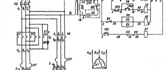
1B265 Block diagram of a multi-spindle lathe
Block diagram of a multi-spindle lathe 1B265
- iVshp – guitar settings for spindle speed
- iРВ – guitar camshaft speed settings
- iVI – guitar setting the rotation speed of the tool spindle
- nshp – spindle rotation speed
- nin – tool spindle rotation speed
- Spop – cross feed
- Sprod – longitudinal feed
Equipment design
Traditionally, in lathes, the forming movement is the rotation of the main spindle, and the feed movement is the movement of the support in the direction opposite to the rotation axis. With such a cutting process scheme, a number of design difficulties are inevitable in ensuring rigidity, vibration resistance and positioning accuracy of the caliper, especially when processing high-precision parts at high speeds. To solve this problem, Swiss designers found a non-standard and revolutionary solution for those times. They created a manual lathe (and then an automatic lathe), in which the support with the tool is stationary, and the feed movement is carried out by a movable spindle head in the direction of the rotation axis (i.e., the rotating part slides onto a stationary cutter).
Although the CNC automatic longitudinal turning machine differs significantly in its production characteristics from the first machines of this type, it has the same traditional layout and composition of the main components and assemblies:
- solid cast bed with guides for the headstock;
- movable headstock with a hollow spindle and collet clamp;
- steady bushing;
- block of fixed supports with cutters;
- device for feeding bar blanks through a spindle.
A modern automatic lathe is a multifunctional machining center with numerical control. In addition to traditional components, such equipment may include:
- counter spindle;
- block or turret with driven tool;
- cutter blocks positioned in different planes;
- supplies store;
- parts catcher and conveyor for finished parts;
- coolant supply system;
- chip removal conveyor.
On machines of this type, it is possible to perform independent processing with cutting and driving tools simultaneously of two parts fixed in the spindle and counter-spindle. In addition, precise synchronization of spindle rotation makes it possible to transfer the workpiece being processed from one spindle to another, which allows processing of both ends of the part in one installation. And the presence of a turret head and various blocks of cutting and driving tools makes it possible to perform the entire range of necessary technological operations on one part installation: from turning, drilling and threading to flat and contour milling.
The specific features of automatic longitudinal turning machines include high requirements for the quality of workpieces.
It is believed that the accuracy of the processed rod, profile or wire should be of a higher quality than the part obtained from them. Another feature is the need to use non-rotating steady rest bushings, which are prone to wear and heat, to improve processing accuracy.
1B265 Basic movements in the machine. main drive
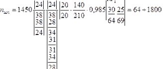
The spindles rotate from the main electric motor through the gearbox mechanism. The rotation speed of the spindles is adjusted by connected gears a, b, c, d (Fig. 4)
Feed drive . The movement of the calipers and sliding holders of the longitudinal caliper is carried out from the camshaft cams in the following sequence:
- quick approach to the workpiece
- working feed
- parking (clearing)
- quick withdrawal
Working feed and stripping occur with slow rotation of the camshaft, withdrawal and supply with fast rotation. The sliding holders of the longitudinal caliper can move as needed, both during slow and fast rotation of the camshaft, depending on the position of the cam on the camshaft.
The fast speed is constant, the working feed speed is adjusted by replaceable gears p, f, g, h.
The magnitude of the working stroke of the transverse calipers is adjusted with replaceable cams, the same for all calipers.
The magnitude of the working stroke of the longitudinal support is adjusted using a rocker mechanism (see Fig. 23; without changing the fists.
The overall stroke of the calipers is always constant. The magnitude of the working stroke of the sliding coin holders can be adjusted by moving the slide along the lever of the independent feed mechanism (see Fig. 32) or by changing the cam on the camshaft. The general course may also change.
Multi-spindle CNC routers
These machines are universal. They allow you to cut, engrave and mill workpieces from a variety of materials: from the hardest (metals, natural stone) to soft (cardboard, leather, polymers, composites, wood).
This equipment is usually divided into two basic groups.
- The first group includes machines designed for enterprises producing serial products.
On them, all spindles are fixed on one common beam. They carry out all milling work synchronously, according to commands from the control program. This is the optimal choice for large-scale production of small-sized products. The last requirement is explained by the fact that their working field is divided as a multiple of the number of installed spindles.
Some machine models are equipped with rotating devices. This makes it possible to mill cylindrical parts. Each part undergoing processing has its own milling zone.
- The second section includes machines that can be considered as an alternative solution for equipment that involves changing tools.
The number of spindles installed on such machines can reach four.
This unit does not provide simultaneous synchronous operation of the latter. However, it copes well with the task of performing several different operations. Each spindle allows installation of an assortment of cutters. This significantly reduces the time required to change tools.
Machines of this type have a reinforced supporting structure. This allows them to be used for processing materials with different properties. Example: soft metals, polymers.
A multi-spindle machine allows, if necessary, conversion to a simplified system (working with one spindle).
The advantages of machines of the type considered include their universal capabilities resulting from various options for fixing parts. It is allowed to use a vacuum table (when working with flat-shaped parts), a rotating device (cylindrical surfaces).
When purchasing such equipment, the customer has the opportunity, taking into account the needs of a particular production, to select different equipment, indicating in the application:
- motor (spindle) of the required power and performance of different brands;
- type of cooling system (air, water, other).
In addition, the choice of milling machines is available for a number of design features.
According to the implemented direction of supply, the following are distinguished:
- inclined;
- horizontal;
- vertical.
Based on the presence (absence) of a console, machines are divided into non-console and console.
According to the number of available racks: two-post, models with one rack.
Layout of machine 1B265
The basic parts of the machine: bed, traverse, gearbox housing and spindle block housing form a rigid frame (portal).
The machine's workspace is located inside the portal. Calipers and various devices necessary for processing parts are installed there. A screw conveyor is installed at the bottom of the working space to remove chips.
The main camshaft of the machine is located in the upper part of the machine in the traverse. Its lower sections, located directly at the supports, are mounted on the left side of the machine in the spindle block housing. There is also a spindle drum and all the mechanisms associated with it: lifting and turning, drum fixation, rod feeding and clamping, material stop.
The main axis of the spindle drum passes through the working space and is the guide of the central longitudinal support. All drive mechanisms: main drive, camshaft drive, tool spindle drive are mounted on the right side of the machine - the gearbox.
The main electric motor is installed in the frame, at the rear of the machine, the bar material is supported by guide pipes with a stand.
Parallel action semi-automatic devices
Parallel-action semi-automatic machines are also designed according to a similar scheme, on all spindles of which, unlike sequential-action semi-automatic machines, identical operations are performed simultaneously and in one cycle of work the processing of as many workpieces is completed as the number of spindles the machine has. Such a machine has a base 5 (lower block) installed a fixed vertical column 4, around which a table with spindles and a hexagonal sleeve with six supports 2 continuously rotate, representing a single whole - carousel 1 (Fig. 5).
Rice. 5. Scheme of operation of a vertical multi-spindle semi-automatic machine : 1 - carousel; 2 — caliper; 3 - drum; 4 - column; 5 - base.
When the liner is rotated, the calipers move along its vertical guides from the stationary drum 3 (upper block), with which they are connected by rods. In a semi-automatic machine, each spindle has its own support, from which the part is processed while the carousel rotates. In one full revolution of the carousel, each spindle passing through the loading zone completes the processing of the part. In this zone, the spindle rotation is first automatically switched off and the part is released from the clamp, and the corresponding support quickly moves up, the finished part is removed and a new workpiece is installed. Then it is automatically clamped, the spindle is given rotation, and the support is quickly brought to the workpiece. Modern semi-automatic machines of this type have four or more working spindles.
Design and operational features of the 1B265 machine
Design and operational features of the machine:
- Installation of the working stroke of the longitudinal support and independent devices is carried out without changing the fists
- For standard machines, the working stroke of the transverse supports is set using a standard set of 8 knuckles, common to all supports. The simplicity of changing the angle of the machine's working stroke by rearranging the corresponding cam of the command device makes it possible in some cases, without changing the cams of the transverse supports, to process various parts of the same type (group adjustment);
- Each of the transverse calipers has an independent drive located in close proximity to the caliper, which ensures high drive rigidity
- The transverse supports are made of a table type with rectangular guides to increase the rigidity and, accordingly, the accuracy of the machine
- There is an electromechanical drive for adjustment operations
- Increased machine precision
Main drive of the machine 1B265-6
From the main electric motor (n = 1460 rpm) through a V-belt drive, the drive shaft I of the machine receives rotation, from which shaft II rotates through gears 4 and 7, connected by replaceable gears a:b. c:d with shaft III to IV - the central shaft of the machine.
The central shaft passes from the gearbox into the spindle block; on its left side sits a gear wheel 41, which meshes with the gears 42 of the spindles.
Machine feed drive 1B265-6
The power stroke drive (feed) is carried out from the central shaft through a worm pair 12, 13, two pairs of replaceable gears e:f, g:b and one constant pair 10, 11 per cup of the electromagnetic power stroke clutch. When the electromagnetic clutch is turned on, rotation is transmitted through a bevel pair 9, 8 to the vertical shaft, then through a gear transmission 19, 16 to the worm shaft 17, which meshes with the worm gear 18 of the camshaft.
In this way, the camshaft located at the top of the machine rotates.
The two lower sections of the camshaft, which impart movement to the lower and middle transverse calipers located in close proximity to them, are connected to the upper camshaft by gears and rotate synchronously with it.
The camshaft also receives rapid rotation from vertical shaft IX, but in this case the latter is driven directly from shaft I through gears 5.6 and an electromagnetic idle clutch on shaft I.
In addition to the automatic camshaft drive discussed above, the latter can be rotated by a setup engine or manually during machine setup. The feed and adjustment drive are switched on using buttons on the control panels.
Adjustment drive . From the flange electric motor, through gears 23, 21 and 20, rotation is transmitted to shaft IX, and from it to the camshaft of the machine. In this case, the electromagnetic clutch on axis XII must be turned off, and on shaft IX must be turned on. The working and rapid speed clutches are turned off, and when the adjustment drive is turned off, the clutch on the XII axis is turned on and brakes the camshaft in the same way as when the feed is turned off. When the setting drive is turned on, the camshaft receives a slow rotation (about 3 rpm), which is used when setting up the machine.
Manual rotation of the camshaft can be carried out by rotating the square on the worm shaft 17.
The input circuit breaker on the electrical cabinet must be turned off.
Drive of tool spindles . During fast drilling, the drive sleeve of the tool spindle receives rotation from the central shaft IV through gears 26, 29 and the replaceable gear “m”. The tool spindle rotates in the opposite direction to the work spindle, thanks to the idler gear.
The rotation speed is adjusted using the interchangeable gear “m”.
For cutting a right-hand thread (or making up a left-hand thread), the movement is transmitted from the central shaft IV, through replaceable gears “i” and “r” to shaft XVI. From it, with the electromagnetic clutch turned on, through gears 27, 24; 25, 28 receives rotation of the tool spindle drive sleeve.
When screwing the tool (or cutting a left-hand thread), the electromagnetic coupling of the shaft ХVI is turned off and the coupling of the shaft XI is turned on. Then the rotation from the central shaft IV to the drive sleeve of the tool spindle is transmitted through the interchangeable gears “i”; "r"; "k"; “l”, then through gears 15, 14; 27, 24; 25.28.
Reaming can be carried out using a quick drilling chain. In this case, another idler gear is installed to ensure the desired direction of rotation of the tool spindle. When used for reaming a thread tapping drive. The replacement gears “k” and “L” are not installed, and the shaft coupling XVI is always engaged.
Auxiliary drives . The screw conveyor is driven by a separate electric motor through a worm pair 30 and 31.
The cooling pumps are driven by their own electric motor, mounted in the same P-180 unit.
Kinematic diagram of a vertical multi-spindle semi-automatic machine of sequential action
The kinematic diagram of one of the seven sections of the main movement and feed drive (the other six sections are similar), as well as the drive and mechanism for rotating the table with spindles is shown in Fig. 3 33
During the main movement, the working spindles VIII receive high rotation speeds from the electric motor M1 (N = 10 kW; n = 1460 min-1) through the gear 16-39 • 39-118 • 118-31, and low speeds through the gear 16-39 • 22 -39 • 22-39 • 39-118 • 118-31 and further from shaft V through replaceable wheels ab, cylindrical pairs of wheels 35-40 and 37-50 (for high-speed versions - through a pair of wheels 37-37). A gear wheel with z = 35 during table rotation is disengaged from a wheel with z = 40, and after rotation it engages with the same gear wheel of another spindle that has come to this position. After each indexing of the table, the spindles acquire the rotation speed of the position in which they crossed. The rotation speed of the spindles in each position is regulated by its own setting link a - b. Synchronizers ensure a smooth, shock-free start of rotation of the spindle in each position. Each spindle, starting with shaft V, has an individual drive chain, but identical with the chains of other spindles. There are as many of these chains as there are working positions (the 1K285 machine has seven of them). The brake that stops the loading position spindle has a mechanism that is activated by a drive common with the synchronizers, engages with the conical cups of the pre-spindle shafts and is similar in design to the synchronizer, but has no rotating elements.
Rice. 4. Kinematic diagram of a vertical multi-spindle semi-automatic lathe model 1K285
The chains of working feeds and rapid movements of the caliper are concentrated in the feed boxes. Using electromagnetic friction clutches built into them, the feed speed is switched from high to low or vice versa (in a ratio of 2.63 times).
The working feed of the calipers is carried out from shaft VI through the worm gear 1-32, a set of replaceable gears cd e-f and then through gears 35-62 (when the electromagnetic clutch EM1 is turned on) or through wheels 58-39 (when the electromagnetic clutch EM2 is turned on ) on shaft XIII. From this shaft, through bevel gears 27-38, rotation is transmitted to the caliper lead screw nut (P = 12 mm). By switching the EM1 and EM2 clutches, you can automatically set two working feeds of the support (small and large) during the processing of the workpiece.
Accelerated feed of the support is carried out from shaft V through bevel gears 20-20 and a pair of cylindrical wheels 70-40 to shaft X. Further, with accelerated supply of the support to the workpiece (electromagnetic clutch EM3 is turned on), rotation is transmitted through gear 57-39 • 38-59 • 27-38 on the caliper lead screw nut. With accelerated retraction of the caliper (electromagnetic clutch EM4 is turned on), rotation is transmitted to the lead screw nut through gears 58-31 • 31-38 • 38-59 • 27-38. In the rapid feed chain, it is possible to reverse the direction of movement by switching on different kinematic chains using two clutches.
Electromagnetic fast-speed clutches of the caliper are interlocked with the same working feed clutches. The clutches are activated using limit switches installed in the control device.
The rotation of the command apparatus shaft is carried out from shaft XIII through a helical gear drive 18-13 and a worm pair 1-66. The command device controls the working and auxiliary strokes of the caliper in the automatic and adjustment cycles. In addition to the limit switches, its body contains a cam shaft and levers. Limit switches do not have springs, which is why the command given to them is remembered until the next press.
After completing the working operations in all positions and retracting all the supports to the upper position, a command is given to turn off the drive of the electric motor M1 and braking the entire system, followed by rotation of the table.
The table is rotated by the M2 electric motor (N = 2 kW; n = 1300 min-1) through a 1-25 worm gear, 14-105 gears and a Maltese cross. A bar with two rollers is installed on the hub of a gear with z = 105. When you turn the wheel with the bar, the rollers fit into a groove on the bottom of the table, turning it. When the bar is rotated 180°, the table rotates one position (1/8 of a turn), and when rotated 360°, it rotates by two positions at once (1/4 of a turn). After the table is rotated, but before the spindles turn on, it is locked.
The table rotation and fixation mechanism is controlled by the action of two cams 2 on the limit switches of the table indexing command apparatus. The cams are mounted on shaft XXII, which receives periodic rotation through gear 105-15 • 4-28.
At the end of the table rotation, the electric motor M2 is turned off and the starting clutch of the main drive motor M1 is turned on.
The machine is equipped with an automated hydraulic device for clamping the part, has a mechanized loading device and a chip removal system. The machines in the six-spindle version are available with chuck diameters of 630 and 800 mm, in the eight-spindle version - 250 and 400 mm.
In addition to the five types of supports already mentioned, special supports can be supplied with the machine upon request, which are a modification of the universal one and allow you to expand the technological capabilities of the machine - to perform:
- processing of longitudinal shaped surfaces using a copy machine;
- processing cones using a cone ruler;
- processing of cylindrical surfaces with rebound at the end of the working stroke;
- machining the end surface simultaneously with the conical surface;
- boring of spherical surfaces
Among the various devices that are equipped with a semi-automatic machine, the most complex is the kinematic chain of the drive of a multi-spindle drilling head. When the head is used, an additional gearbox is attached to the feed box of the corresponding position.
Technical characteristics of the machine 1B265
| Parameter name | 1B265-4K | 1B265-6K | 1B265-8K |
| Main settings | |||
| Accuracy class according to GOST 8-82 | P | P | P |
| Largest size of processed round bar (diameter), mm | 80 | 65 | 50 |
| Largest size of processed square bar (side), mm | 56 | 45 | 35 |
| The largest size of the processed hexagonal rod (diameter of the inscribed circle), mm | 68 | 55 | 43 |
| Maximum rod feed length, mm | 200 | 200 | 200 |
| Maximum processing length, mm | 190 | 190 | 190 |
| Maximum machining length from a longitudinal slide in the rear position, mm | 150 | 150 | 150 |
| Maximum rod length, mm | 3000 | 4000 | 4000 |
| Spindles | |||
| Number of working spindles | 4 | 6 | 8 |
| Distance between spindle axes, mm | 275,7 | 200 | 166,5 |
| Spindle speed, rpm | 61..755 | 73..1065 | 97..1176 |
| Speed of spindles in high-speed version, rpm | 61..1050 | 73..1590 | 97..1810 |
| Tool supports | |||
| Number of longitudinal supports | 1 | 1 | 1 |
| Number of cross slides | 4 | 6 | 6 |
| Maximum total stroke of the longitudinal support, mm | 200 | 200 | 200 |
| Maximum total stroke of upper transverse supports, mm | 90 | 80 | 80 |
| Maximum overall stroke of the lower transverse supports, mm | 80 | 70 | 80 |
| Maximum total stroke of the middle transverse calipers, mm | — | 70 | 70 |
| Camshaft rotation speed at idle, rpm | 8,8 | 10 | 10 |
| Idling time, s | 3,9 | 3,5 | 3,5 |
| Electrical equipment | |||
| Number of electric motors on the machine | |||
| Electric motor of the main drive (spindles), kW | 30 | 30 | 30 |
| Adjustment rotation electric motor, kW | |||
| Electric drive motor for chip conveyor, kW | |||
| Lubrication pump electric motor, kW | |||
| Cooling pump electric motor, kW | |||
| Installed power, kW | |||
| Dimensions and weight of the machine | |||
| Dimensions of the machine without attachments (length width height), mm | 5515 x 2050 x 2170 | 6355 x 2050 x 2170 | 6220 x 2050 x 2170 |
| Machine weight, kg | 14500 | 14500 | 14500 |
- Skhirtladze A.G., Novikov V.Yu. Technological equipment of machine-building industries, 2002, p.162.
- Boguslavsky B.L. Semi-automatic turning machines, automatic machines and automatic lines, 1961
- Volkevich L.I., Kuznetsov M.M., Usov B.A. Automatic machines and automatic lines, 1976
- Zazersky E.I., Mitrofanov N.G., Sakhnovsky A.G. Handbook for a young operator of automatic and semi-automatic lathes, 1987
- Itin A.M., Rodichev Yu.Ya. Setup and operation of multi-spindle semi-automatic lathes, 1977
- Kamyshny N.I., Starodubov V.S. Design and adjustment of automatic and semi-automatic lathes, 1975
- Lisova A.I. Construction, adjustment and operation of metalworking machines and automatic lines, 1971
- Pozhitkov A.Ya., Safro I.D. Setting up single-spindle automatic lathes. Reference manual, 1978
- Pronikov A.S. Metal-cutting machines and automatic machines, 1981
- Feshchenko V.N. Processing on turret lathes, 1989
- Fomin S.F. Construction and adjustment of turret lathes, 1976
Bibliography:
Related Links. Additional Information
- Classification and main characteristics of turning
- Selecting the right metalworking machine
- Multi-start thread. Methods for cutting multi-start threads on a lathe
- Graphic signs for lathes
- Friction clutch of a screw-cutting lathe
- Lathe repair technology. Repair of bed and support guides
- Lathe repair technology. Repair of headstock and tailstock
- Lathe spindle repair
- Methodology for checking and testing screw-cutting lathes for accuracy
- Directory of lathes
- Manufacturers of lathes
Home About the company News Articles Price list Contacts Reference information Interesting video KPO woodworking machines Manufacturers
Technical features
Technical parameters depend on the material to be processed, its size and weight. First of all, an approximate diagram of the processing technology is created, the size of the workpiece at each stage is indicated. After which a machine is selected for specific tasks.
It happens that the space to place the machine is limited, then it is recommended to purchase a desktop version. It has some advantages, among which are its light weight, size and the ability to be easily transported.
It is always necessary to ensure that the machine does not slip on the surface on which it is installed due to the vibrations generated.
Feedback on the use of multi-spindle 3D CNC milling machines is quite positive. However, they depend on how correctly the machine is selected for specific purposes and tasks.