Information about the manufacturer of the table lathe 16t02p
The manufacturer of the table lathe 16T02P and 16T02A is the Kirovakan Precision Machine Tools Plant in Kirovkan (today Vanadzor), Armenia.
The main purpose of the machine was to teach turning in schools, vocational schools, technical schools, and are widely used in laboratories, training and repair shops.
Currently, production of the machines has been discontinued.
Machine tools produced by the Kirovakan Precision Machine Tools Plant
- 1D601
- table lathe Ø 125 - 1E604
- high-precision screw-cutting lathe Ø 200 - 16B05P
- high-precision screw-cutting lathe Ø 250 - 16T02P
- high-precision table lathe Ø 125 - 16T04a
- especially high precision lathe Ø 200 x 350 - 16U03P
- high-precision screw-cutting lathe Ø 160 - 16U04P
- high-precision screw-cutting lathe Ø 200 - 1600
— high-precision table lathe Ø 100 - 1603
— high-precision screw-cutting lathe Ø 160 - S193n
- high-precision table lathe Ø 200 - S-193
- high-precision table lathe Ø 200 - S-155
,
SA-155
- tabletop drilling machine Ø 3
Brief information about the manufacturer
The manufacturer of 16T02P machines is a plant in Vanadzor, Republic of Armenia. In the past it was the Kirovakan Precision Machine Tools Plant. The manufacturer produced 2 modifications of these machines: high precision and especially high precision. At the moment, the machines in question are no longer produced, but due to their durability and reliability they are still widely used.
Purpose
The main purpose of these machines is to use them in precision industries, as well as as educational material in schools and technical schools. Successfully performs fine and precise work on centers, collets, chucks and faceplates. The faceplate is used when working with large workpieces, and a collet chuck is used to secure thin parts.
The equipment is designed to perform all standard turning operations, including threading, boring holes, as well as milling and grinding operations on metal workpieces.
Industry
Thanks to its increased accuracy parameters, a table-top lathe is used in various industries that require fine processing of the workpiece.
Sentinel
This is the most commonly found machine in watch workshops; one might say it is a watch lathe. It is capable of accurately processing the smallest parts, with high precision requirements. Of all the possible analogues, this machine is the best option for small watch shops.
Radio engineering
This is another area of production that requires special precision in the processing of workpieces. In the radio engineering industry, 16T02P machines are used both in private workshops and in large-scale production.
Laboratories
The laboratories are also equipped with desktop machines for processing experimental workpieces. In terms of processing accuracy, the machines in question are the most optimal option.
Workshops
Small workshops do not require large, heavy machines. For production and work at such enterprises, standard desktop equipment is sufficient.
Schools
When teaching how to operate a lathe in schools, colleges and technical schools, desktop equipment is also used. Its performance and accuracy are enough to process training workpieces and learn how to carry out all the basic standard turning operations.
16T02P Table lathe. Purpose, scope
Tabletop lathes models 16T02P (increased accuracy) and 16T02A (especially high accuracy) are designed to perform various precision turning operations with the installation of the workpiece in centers, a collet chuck and on a faceplate. Thanks to the use of special devices on the machines, which are supplied by the manufacturer upon special order and for an additional fee, it is also possible to carry out grinding, milling and boring operations.
The scope of application of machines 16Т02П and 16Т02А are experimental and tool shops of watchmaking, instrument-making, radio engineering and other industries, as well as various laboratories, workshops, etc.
The scope of application also includes school and field workshops, technical schools, laboratories, as well as at home for lovers of turning and model designers, which will help to use leisure time for the development of labor skills and ingenuity.
16T02P lathe is the plain bearings in the headstock housing on which the spindle is mounted. 16T02P machine the spindle is mounted on rolling bearings - precision ball bearings.
Analogs
There are several analogues of the 16T02P table lathe, but the main and most common modification is the following models:
- 16T02A is a machine of particularly high precision. In terms of other technical parameters, it fully corresponds to the equipment in question.
- 1Р103 is a high-precision machine for small-scale production.
- T-28 is a machine with a normal level of accuracy with minimal dimensions.
- 1B023 is another analogue of desktop turning equipment.
All varieties can be used in small industries, private turning workshops, classrooms of schools, colleges and technical schools.
The 16T02P table lathe is a small type of equipment that is successfully used in the production of watches, electrical equipment and other goods that require high precision during assembly. The technical characteristics allow for delicate work in small-scale production, as well as training operations for school workshops.
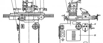
16T02P General view of the lathe
photo of table lathe 16t02p
photo of a set of table lathe 16t02p
Documentation, passport
The desktop machine comes with a passport, which includes an instruction manual, as well as a detailed description of the machine itself with all its components. You should definitely read the machine’s passport, as it contains information about proper maintenance of the equipment and safety rules.
For private workshops and home use, the section on repair and adjustment of the unit will also be useful. This section will help you replace or adjust the main components of the structure if they break.
The lathe machine passport can be downloaded for free from the link - Lathe machine passport 16T02P.
16Т02П Arrangement of components of a lathe
Location of the main components of the lathe 16t02p
List of components of the lathe 16T02P and 16T02A
- Bed - 16T02P.01.00, - 16T02P.01.00A
- Headstock - 16T02P.02.00, - 16T02P.02.00A
- Caliper - 16T02P.03.00, - 16T02P.03.00A
- Tailstock - 16T02P.04.00, - 16T02P.04.00A
- Electrical equipment - 16T02P.08.00, - 16T02P.08.00
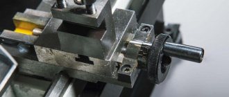
16T02P Location of lathe controls
Location of controls for lathe 16t02p
List of controls for lathe 16T02P and 16T02A
- Flywheel for collet holder, collet clamp and other accessories
- Eccentric mechanism handle for tensioning belts
- Tool clamp screw in tool holder
- Cutter height adjustment nut
- Quill clamp handle
- Handle for the longitudinal slide of the caliper
- Quill movement flywheel
- Caliper clamping and fixing handle
- Start control button
- Stop control button
- Caliper cross slide dial handle
- Circuit breaker toggle switch
- Counter drive bracket clamp eccentric handle
- Tailstock clamping and fixing handle
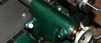
16T02P Lathe bed
Lathe bed 16t02p
The bed of machines 16T02P and 16T02A is a cast iron monolithic part on which hardened steel guides 1 with a ground flat-prismatic profile are fixed.
The headstock is installed on the top left of the frame guides, and the tailstock is installed on the right.
A push-button station is mounted in the niche of the frame. Between the guides there is a T-shaped groove intended for fastening units.
The machine bed is attached to table 4, electric motor 3 with counter drive 2 is mounted on a bracket. To avoid vibrations in the machine, a rubber gasket 5 is placed between the table plane, the supporting plane of the frame and the electric motor, which serves as a partial vibration damper.
The tension of the V-belt from the electric motor to the counter-drive is carried out using an eccentric mechanism 7, which fixes the belt in a given position. The belt is tensioned by rotating the counter-drive bracket 2 around the engine axis and then fixing it in the desired position using clamp 6.
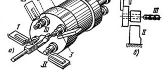
16Т02П Headstock of lathe
Headstock of lathe 16t02p
The headstock of the machine model 16T02P (Fig. 7) is installed on the bed and secured with eccentric clamps 1. The spindle 2 is assembled in the headstock housing on three precision ball bearings. The bearings 3 installed in the front support are angular contact. Bearings 4, installed in the rear support - radial. Receiving pulley 5 is located on the rear spindle support. The hole in the spindle is made for a collet, which ensures greater accuracy when processing parts in a collet.
Headstock of lathe 16t02p
Spindle 1 of the headstock of the machine model 16T02A (Fig. is assembled on two sliding supports with conical contact surfaces in the headstock body. The working surfaces are lubricated using a sprayer 2, which directs oil from the headstock body through special lubrication grooves.
There are two eyes installed on the headstock body: one to monitor whether the headstock is filled with oil to the required level, and the second to monitor the flow of oil into the bearing grooves.
The bearings are adjusted by rack 3.
Design of lathe 16Т04А
bed
The bed is a rigid cast iron casting on which a wide prism 1 is installed for the headstock and tailstock. The prism has a groove 2 for the clamping pins of the headstock and tailstock.
At the location where the headstock is installed, the frame is widened. There is a window in the upper part for the passage of belts.
The bed is installed and secured to the machine stand.
Cabinet
The cabinet contains individual components of the machine. A variator is mounted on the left side of the cabinet on the lower frame.
In the right section of the cabinet there is an electrical equipment cabinet, between it and the variator there is a cooling tank with an electric pump.
At the top of the cabinet there is a tray for collecting chips and coolant when working with cooling. The coolant is drained through the tray filter into the cooling tank.
There is an opening in the front part of the cabinet to accommodate the worker’s legs.
On the front top of the cabinet there is a machine control panel, next to which there is a drawer for storing accessories.
The cabinet openings are closed with quick-release covers with spring latches.
The cabinet is attached to the foundation with five foundation bolts.
Variable speed drive
Variator of lathe 16t04a
The unit consists of a variator with a wide V-belt and a two-speed gearbox. The first shaft of the variator 1 is driven by a flanged electric motor 9. On the first shaft of the variator there is a spring-loaded pulley 2. On the second shaft 4 there is a controlled pulley 5. The second shaft of the variator is also the drive shaft of the gearbox; there are two gears on it. Small gear 7 moves along the shaft and switches gearbox speeds. The gearbox housing b is mounted on a housing 8 attached to the variator housing 3.
Using a threaded bushing and two screws, housing 6 is rotated relative to the variator body to tension the belt drive connecting the variator to the headstock.
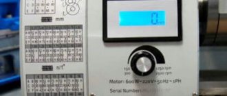
The control mechanism for the variator and gearbox (Fig. 12) is located on top of the variator body.
Control handwheel 1 moves the variator disc. Using handle 2 located on the dial flange, the gearbox speeds are switched. The control handwheel is connected by a planetary gear to a spindle speed adjustment scale. Part 3 has two scales corresponding to direct spindle engagement and spindle engagement through the headstock.
Front headstock of machine 16t04a
The front headstock of the machine is installed on the bed (Fig. 6, 7).
The headstock housing houses the take-up pulley and spindle. The spindle supports are equipped with reversible hydrodynamic plain bearings.
The receiving pulley 7 is mounted on a sleeve 6, coaxial with the spindle 1, which has its own supports in the headstock body. Rotation of the spindle from the pulley is transmitted by an elastic diaphragm 8, protected from destruction during starts, spindle reverses and overloads by a rigid gear coupling with increased lateral clearances.
Spindle bearings are lubricated using a commercial lubrication station. Rotation from the variator to the headstock is transmitted by two V-belts 0-1400Ш GOST 1284-68.
Spindle head of lathe 16t04a
Spindle head of lathe 16t04a
Front headstock of the machine 16t04p
Spindle head of lathe 16t04p
The headstock is installed and secured to the top left of the frame.
The headstock housing 1 contains a spindle 5, a gearbox and a control mechanism.
Receiving pulley 3 of the headstock is installed on bushing 4, coaxial with the spindle.
The rotation of the spindle is transmitted from the pulley directly when the gear coupling b is engaged or through a transmission with a gear ratio of 1:4.
A double-row roller bearing is installed in the front spindle support, which absorbs radial loads.
The rear supports of the spindle and drive pulley are located in cup 2.
The rear spindle support has two angular contact bearings that absorb axial loads.
On the left side of the headstock, a lever collet clamp is installed on the support collar of flange 10. The spindle has a conical hole for installing a collet.
The movable gears and clutches are controlled by a handle located on a cover mounted on the front wall of the headstock housing.
Lubrication in the front support is carried out by splashing, in the rear support - wick lubricant.
Tailstock
The tailstock is installed on a wide prism of the frame and secured in the desired position with handle 3.
Quill 1 has a constant direction in the body and is moved by handwheel 2 at its right end.
The amount of movement of the quill is measured using the scale on the quill. The quill is clamped with a handle that tightens the terminals.
Ball oilers are installed for lubrication.
Caliper
The longitudinal slide of the caliper 1 is fitted along the guides of the frame and secured to it with clamps.
On top of the guides of the longitudinal slide, the transverse slide 3 is moved using a screw 2.
A rotating slide 5 with an upper carriage 4 is installed on the transverse guides. The upper carriage of the support has grooves for securing a four-position or single-position tool holder.
16T02P Lathe support
Lathe support 16t02p
The support of the machines is a cross type with longitudinal and transverse movements of the slide by hand. A certain position on the frame is fixed by handle 1.
Backlash in screw pairs of longitudinal and transverse slides is selected using split nuts 2 and 4.
Backlash in the guides is selected using wedges 3 and 5.
Electrical equipment of lathe 16T02P. General information
16T02P Electrical circuit of a lathe
Electrical diagram of lathe 16t02p
The machine is equipped with an asynchronous electric motor with a squirrel-cage rotor of the DPT-P-21-4-S type with a power of N = 0.25 kW, p = 1400 rpm. Increased accuracy in terms of vibration levels, noise and accuracy of installation dimensions.
Voltage in the power control circuit ~ 380 V, frequency 50 Hz.
The electrical circuit provides for starting and stopping the electric motor using control buttons 2KU “Start” and 1KU “Stop”.
Description of the circuit diagram of the lathe 16T02P
Voltage is supplied to the power control circuit by turning on the automatic circuit breaker AB.
By pressing the 2KU button, the no. O. contacts, the power circuit receives power and the electric motor begins to rotate. When the contact block K (1-2) of the starter is closed, the circuit switches to self-power.
The electric motor is stopped by pressing the 1KU “Stop” button, accompanied by an open circuit.
Motor protection
The electrical circuit of the machine provides protection of the power control circuit from short circuits and overloads by an automatic circuit breaker AB, as well as protection from voltage failure by means of n. O. magnetic starter contact.
Electrical equipment
Electrical circuit of lathe 16t04a
The electrical equipment of the machine contains:
- 1M asynchronous spindle drive motor
- 2M cooling pump electric motor, available upon special order
- electric motor of the 3M device, available upon special order
- starting and protective equipment
- local lighting
Description of the circuit diagram
By turning the AB circuit breaker, voltage is supplied to the operating and control circuits.
When the 2KU button is pressed, the 1M electric motor rotates to the right using the gearbox starter.
When you press the 1KU button with contact 3-5, the power supply circuit of the gearbox starter is broken, and contact 3-29 turns on the circuit of the CT starter, which performs induction-dynamic braking of the engine with its contacts. Contact KT (O-B11) short-circuits the first stator winding, contact (C1-C12) supplies a pulsating current to the second winding through the power diode VK, contact (A1-A11) supplies alternating current to the third winding.
When you press the 3KU button, the 1M motor rotates to the left using the CL starter.
At points 23-25 n.a. contacts of the KP or CL starters prepare the KO starter for switching on.
By turning the HV switch, the KO starter is turned on. The KO starter, with its power contacts, turns on the 2M or 3M electric motor or both electric motors simultaneously, depending on whether they are connected to the power circuit via plug connectors ШР1 or ШР2.
Protection
The electrical circuit of the machines provides protection against short circuit currents, provided by fuses and a circuit breaker.
Overload protection provided by thermal relays;
Zero protection using magnetic starter
Main technical characteristics of the machine 16T02P and 16T02A
Technical characteristics (main parameters and dimensions: for machine 16T02P TU 2-024-2319-74, for machine 16T02A TU02-024-2320-74).
| Parameter name | 1D601 | 16T02P | 16Т02А |
| Basic machine parameters | |||
| Accuracy class | N | P | A |
| The largest diameter of the workpiece above the bed, mm | 125 | 125 | 125 |
| The largest diameter of the workpiece above the support, mm | 75 | 75 | 75 |
| Height of centers above flat bed guides, mm | 68 | 68 | |
| Maximum length of the workpiece at centers (RMC), mm | 180 | 250 | 250 |
| Maximum length of the workpiece processed without reinstalling the support, mm | 55 | 65 | 65 |
| Maximum cutter height, mm | 8 x 8 | 8 x 8 | |
| Spindle | |||
| Diameter of through hole in spindle, mm | 10,2 | 10,2 | 10,2 |
| Morse taper spindle | Morse KM2 | Morse 0 | Morse 0 |
| Number of speed steps for direct spindle rotation | 3 | 6 | 6 |
| Spindle direct rotation frequency, rpm | 700, 1400, 2800 | 400, 630, 1000, 1250, 2500, 4000 | 400, 630, 1000, 1250, 2500, 4000 |
| Caliper. Submissions | |||
| Longitudinal movement of the caliper | Manual | Manual | Manual |
| Maximum lateral movement of the caliper, mm | 60 | 60 | |
| Transverse movement of the caliper by one division of the dial, mm | 0,05 | 0,01 | 0,01 |
| Maximum movement of the upper (incisor) slide, mm | 65 | 65 | |
| Movement of the cutting slide by one division of the dial, mm | 0,05 | 0,01 | 0,01 |
| Angle of rotation of the upper carriage of the caliper, degrees | ±30 | ±30 | |
| Tailstock | |||
| Morse taper tailstock | Morse 1 | Morse 0 | Morse 0 |
| Maximum movement of the quill, mm | 35 | 40 | 40 |
| Electrical equipment | |||
| Main drive electric motor, kW | 0,180 | 0,25 | 0,25 |
| Dimensions and weight of the machine | |||
| Machine dimensions (length width height), mm | 680 x 200 x 220 | 695 x 520 x 300 | 695 x 520 x 300 |
| Machine weight, kg | 30 | 35 | 35 |
- Table lathe 16T02P, 16T02A. Operating manual 16T02P.00.000 RE, 1976
- Acherkan N.S. Metal-cutting machines, Volume 1, 1965
- Batov V.P. Lathes., 1978
- Beletsky D.G. Handbook of a universal turner, 1987
- Denezhny P.M., Stiskin G.M., Thor I.E. Turning, 1972. (1k62)
- Denezhny P.M., Stiskin G.M., Thor I.E. Turning, 1979. (16k20)
- Modzelevsky A. A., Muschinkin A. A., Kedrov S. S., Sobol A. M., Zavgorodniy Yu. P., Lathes, 1973
- Pikus M.Yu. A mechanic's guide to machine repair, 1987
- Skhirtladze A.G., Novikov V.Yu. Technological equipment for machine-building industries, 1980
- Tepinkichiev V.K. Metal cutting machines, 1973
- Chernov N.N. Metal cutting machines, 1988
Bibliography:
Related Links. Additional Information
- TV-4 lathe. Video
- School lathes. Review
- Classification and main characteristics of turning
- Selecting the right metalworking machine
- Multi-start thread. Methods for cutting multi-start threads on a lathe
- Graphic signs for lathes
- Friction clutch of a screw-cutting lathe
- Methodology for checking and testing screw-cutting lathes for accuracy
- Directory of lathe manufacturing plants
- Directory of lathes
Home About the company News Articles Price list Contacts Reference information Interesting video KPO woodworking machines Manufacturers