Jet BD-3 Benchtop Lathe Manufacturer Details
the Jet BD-3 benchtop lathe is JPW Tools AG Switzerland. Website address: www.jettools.com
Behind the JET is a company with extensive experience in the production of wood and metalworking machines. Since 1950, JET has been developing, producing and selling machines in the USA, where it is the market leader.
Machines manufactured by JPW Tools AG, Switzerland, China
- JBTS-10
– circular table saw - JKM-300
– combined woodworking machine - JPS-10ts
– stationary circular saw - JPT-10B
— tabletop jointing-thicknessing machine - JPT-310
– stationary planer-thicknesser machine - JRT-2
– milling table - JTS-315sp
– construction circular saw - JWP-12
- table thickness planer - PKM-300
– combined woodworking machine - BD-3
— table lathe Ø 100 - BD-7
— tabletop screw-cutting lathe Ø 180 - BD-8
— tabletop screw-cutting lathe Ø 210 - BD-920w
– table lathe Ø 220
Recommendations for use
Electrical diagram
Work on the JET BD-3 lathe should only begin after a detailed reading of the operating instructions and technical data sheet. Despite the simplicity and reliability of the design, all safety and maintenance requirements for the equipment must be met.
After purchase and unpacking, all traces of protective lubricants must be removed. For this, solvent or paraffin is used. Then the equipment is checked and its installation location is selected. The height of the work table should be such that you do not have to bend down while operating the machine. Particular attention is paid to the degree of illumination of the workplace.
Recommendations for operating the machine:
- first start. To do this, turn the potentiometer until it clicks. After this, to start the engine and increase the speed, the handle is turned further. The spindle head must be securely fastened. The operability of the machine is checked at minimum and maximum engine speeds;
- processing of the part. It must be securely fastened between the headstock and tailstock. Then the cutter of the desired shape is installed. When starting the machine, the cutter should not come into contact with the workpiece. Only after reaching the required number of revolutions can processing begin. If the electric motor is overloaded, automatic protection will operate. In this case, it is necessary to turn the potentiometer to its original state and wait until the safety device turns off;
- service. Before starting work, the machine must be cleaned of chips and metal dust, and the functionality of its elements must be checked. Lubrication of moving parts must be done using special fluids. To replace the motor brushes, you need to unscrew the cover.
In general, this model of a household lathe is unpretentious in operation. It is only important not to exceed the rated load on the caliper and electric motor. If the operating rules are followed, the equipment can last for more than one year.
When setting the position of the cutter, you must make sure that its cutting edge is below the axis of rotation of the workpiece. Otherwise, the load on this component will sharply increase and the likelihood of its failure will increase.
Jet BD-3 table lathe. Purpose, scope
This machine is a “hobby” class machine and is intended for individual (household) use, i.e., due to its design features and technical characteristics, the machine is not intended for use in production.
The Jet BD-3 metal lathe is designed for processing workpieces made of metal, wood, and all types of plastic by turning.
The Jet BD-3 machine is a tabletop lathe and is intended for all kinds of turning work:
- grooving and boring of cylindrical, shaped and conical surfaces
- drilling, chamfering
- boring
- segment
- A wide range of adjustment of the rotation speed and longitudinal feed speed increases the arsenal of the cutting tools used
The traditional visual layout of the machine in combination with a proven kinematic diagram allows you to confidently provide turning with accuracy class “H” over a long service life.
Compared to small-sized machines offered on the market, it is easy to operate, reliable and durable.
The machine operates from a single-phase alternating current network with a voltage of 220 V and a frequency of 50 Hz.
The machine can be operated under the following conditions:
- ambient temperature from 10 to 35 °C
- relative air humidity up to 80% at a temperature of 25 °C
Design features of a desktop mini-metal machine
The JET BD-3 unit is characterized by its small overall dimensions. The design features allow you to perform a sufficient amount of turning work at home and in small production.
Massive cast iron bed
This is one of the advantages of the unit in question. It has a vibration-resistant frame cast from durable cast iron. It is this frame that helps resist vibration and serves as a reliable basis for the entire unit.
Ground guides
The machine guides are carefully polished. As a result, the carriage moves without jerking or additional effort.
Adjusting the gaps
To compensate for the wear of the guides, the craftsmen who designed the machine invented the ability to adjust the gaps. This is done using wedge strips.
Chuck protective screen
The cartridge is equipped with a screen, which is equipped with a special switch. Therefore, when the screen is raised, the motor is automatically switched off. There is also a separate emergency shutdown button. It is used in emergency situations when it is urgently necessary to stop the operation of the machine.
Rubberized supports
Rubber-coated bed supports guarantee vibration-free operation on the workbench. This extends the life of the machine and reduces wear.
Possibility of equipment
In addition to the main components, the machine can be equipped with additional tools and thus expand its functionality.
Longitudinal automatic transmission
This is additional equipment that helps solve many additional problems. Automatic transmission makes it possible to increase equipment productivity and speed up some processes on a lathe.
Upper sliding support
It is also installed additionally to perform some operations.
Brushed motor
The machine is equipped with a commutator motor with a voltage of 230 W.
Variable speed drive
This is a mechanical friction transmission. It provides a smooth change in angular velocity. The variator installed on this equipment ensures the reliability of the machine, increases efficiency and extends the service life of turning equipment.
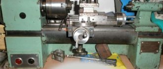
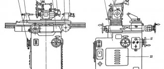
General view of the Jet BD-3 lathe
Location of components of the Jet BD-3 lathe
Specification of components of the Jet BD-3 lathe
- Belt drive cover
- Headstock
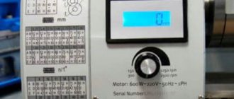
- Emergency switch
- Spindle speed controller
- Overload indicator
- Voltage indicator
- Spindle screen
- Three jaw chuck
- DC motor
- Tool holder (optional)
- Tailstock
- Tailstock flywheel
- Longitudinal flywheel
- Stand
- Lateral flywheel
- Caliper movement screw
- Guides
Purpose of the machine, pros and cons of operation
Appearance
This type of equipment is designed for turning metal and wood products using the rotation method. It is characterized by a standard arrangement of elements, small dimensions and fairly good performance characteristics.
Using this lathe model, you can perform turning and boring of cylindrical workpieces, drilling, chamfering, and cutting. Additionally, it is designed for grinding rotating surfaces. It is only important to choose the right cutter of the required shape. The equipment has intuitive functionality and a simplified kinematic diagram.
The advantages include the following machine parameters:
- small overall dimensions;
- switching the speed using a potentiometer. This makes it possible to reduce or increase the rotation speed of the headstock without stopping the electric motor;
- low noise level is due to the characteristics of the electric motor;
- a through hole in the front spindle head allows the installation of a rod;
- threaded mounting cones for installing various attachments - spindles, drill chucks.
The disadvantage is the lack of spot lighting. Therefore, they often modernize the machine. The mechanism for turning on the equipment using a potentiometer is also inconvenient. Often a separate motor start relay is installed.
To ensure safety, the design includes a protective screen and an emergency stop of the electric motor. However, the first one is small in size and is located in the headstock area.
Description of the design of the Jet BD-3 lathe
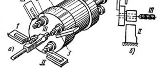
Headstock
The motor transmits rotation to the spindle using a toothed belt. The spindle speed can be smoothly varied and is adjusted using the handle (4) located on the main control panel. A self-centering chuck (8) with three jaws is mounted on the spindle. To remove the chuck, simply remove the three mounting nuts from the back of the spindle boss so that it can be pulled out freely along with the three locating pins.
Note: The chuck has a protective shield (7). Opening the screen cuts off the lathe's main power, so keep the screen closed while operating.
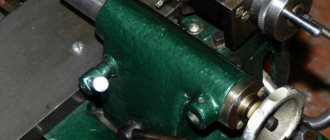
Tailstock
The tailstock casting (11) can be moved along the bed and installed in any desired position, its position is fixed by two screws (at the front of the tailstock) which lock and loosen the tailstock wedge, and you can remove or adjust the tailstock casting.
Caliper and cross guides
On the support there are transverse guides on which the tool holder (10) is installed, which allows complex and delicate operations to be performed. It can be moved by the lead screw, through the drive nut, to provide automatic feeding when the Gripper (1) is installed in the right position.
A. Startup procedure during installation
To begin, plug the lathe into the socket, then release the Emergency Stop Switch (3), the power indicator should light up.
Turn on the machine by GENTLY turning the Speed Control Knob (4) clockwise. There will be a clicking sound when the power is turned on, but the spindle will not rotate until you turn the crank a little more clockwise. As you continue to rotate the handle, the speed will progressively increase. Let the machine run for about 5 minutes, during which time gradually increase the spindle speed to maximum. Then let it run for at least 2 minutes at this speed before turning off the machine and unplugging it from the power source. Check that all components are reliable and work freely and correctly. Also check that all fasteners are secure. If any adjustment is necessary, refer to the appropriate “Settings and Adjustments” section.
B. Starting under normal conditions
- All the above precautions must be taken to ensure that the workpiece rotates completely without any difficulty.
- Start the machine as indicated in section A above
- If the machine has finished working or needs to be left unattended, turn the Speed Control Knob to the OFF position and then disconnect the machine from the power source. WARNING: The power supply system of this machine has an automatic overload protection device. If cutting or drilling is too deep, the system will stop operating and the yellow light (6) on the main control panel will come on. Simply turn the Speed Control Knob (4) to off and then back on. The system will start working again and the yellow light will automatically go out.
Operation of the machine. Turning
Before running the machine as described above, it is necessary that the setup for the type of work to be carried out is fully checked. Below are guidelines on the basic principles of how to set up a lathe for simple turning operations.
ALWAYS plan your work. You will need the various measuring tools you may need, such as micrometers, calipers, calipers, etc. Select a cutting tool that can do the job you want and install it in the tool holder with the smallest overhang possible, securing it using three hex cap screws turnkey (ideally, the protrusion should be approximately 6 mm, but no more than 8 mm for a straight tool). It is IMPORTANT to ensure that the end of the cutting tool is located on the axis of rotation of the part, or slightly below it. Under no circumstances should it be higher than the axle. If necessary, shims must be used under the tool to achieve the correct height, or if the end of the tool is too high, the only option is to select a different tool or mill the tool holder. To check if the edge of the tool is at the correct height, position it so that the tip almost touches the center of the tailstock taper. They must match. If necessary, make adjustments using shims, grinding off the tip, or selecting another tool. When the tailstock is not in use, you can remove it completely by loosening the mounting nut at its base and sliding it freely along the bed. Mark a point on the surface of the workpiece where you want to finish turning, such as a lip, using a scraper or similar, and move the slide so that the cutter is directly opposite the mark, then rotate the cross slide so that the tool touches the surface of the workpiece. As you perform these manipulations, rotate the chuck by hand to ensure that it will not touch anything if you are turning, for example, that there is sufficient clearance between the slide, cross slide, tool holder, or tool and chuck.
If everything is in order, then retract the cutter and move the support away from the headstock, then rotate the cutter towards the workpiece approximately along the length of the cut, while rotating the workpiece by hand, and using the chuck. Continue to slowly advance the cutter until it touches the surface. Fix this position by zeroing the scale on the transverse guides, i.e. turning the sliding scale until the cutter is a short distance from the right corner of the workpiece. Turn the cross slide again one full turn until the zero mark is aligned. IMPORTANT: If you miss the zero marks, move them back at least half a turn, then slowly bring the marks back together. Whenever you use the scale as an indicator to advance the cross slide or cross slide cutter slide, ALWAYS use this procedure to line up the marks. Be sure to take this into account. Continue turning the handle until it reaches the desired depth of cut.
Design features
Equipment components
The standard layout of the elements of the JET BD-3 machine makes it possible to perform operations even with minimal turning skills. But before that, it is recommended to study the specifics of its design and become familiar with the parameters of its constituent elements.
The frame is made of durable cast iron, the guides are carefully polished, which allows the carriage to move without jerking or additional effort. The machine is designed to be connected to a 220 V household power supply. The electric motor has a fairly low power, which affects the degree of processing with a cutter in one pass.
Let's consider the design features of the equipment components:
- headstock The transmission of torque from the electric motor occurs using a toothed belt. The chuck is self-centering and has three jaws. When the protective shield is opened, the engine is automatically switched off;
- caliper and guides. Movement occurs when the lead screw rotates. There is an automatic feed function if the gripper is installed in the right position;
- tailstock. Can move along the guides of the bed. There are two screws for fixation;
- Tool holder. Designed for fixing one small incisor. Able to withstand heavy loads during turning of materials.
Adjusting the position of the cross slide is done by loosening or tightening the screw located on the side of the structure.
The standard equipment of the machine includes a 5.5*7 key, one fuse and a screwdriver. Cutters must be purchased separately based on their actual tool holder characteristics.
Jet BD-3 lathe assembly diagram
| No. – Name – Quantity | No. – Name – Quantity |
|
|
Technical characteristics of the Jet BD-3 machine
| Parameter name | Jet BD-3 |
| Basic machine parameters | |
| The largest diameter of the workpiece above the bed, mm | 100 |
| The largest diameter of the workpiece above the support, mm | |
| Maximum length of the workpiece at centers (RMC), mm | 150 |
| Recommended turning depth per pass, mm | |
| Maximum turning depth in one pass, mm | 0,25 |
| Maximum cutter holder size, mm | 8 x 8 |
| Spindle | |
| Diameter of through hole in spindle, mm | 10 |
| Spindle connection | M14 x 1 |
| Number of speed steps for direct spindle rotation | B/s |
| Spindle direct rotation frequency, rpm | 100..3800 |
| Diameter of lathe chuck, mm | |
| Caliper. Submissions | |
| Maximum longitudinal movement of the caliper carriage, mm | |
| Longitudinal movement of the caliper by one dial division, mm | |
| Maximum lateral movement of the caliper, mm | 50 |
| Transverse movement of the caliper by one division of the dial, mm | |
| Angle of rotation of the cutting slide, degrees | ±45° |
| Limits of longitudinal working feeds of the caliper, mm/rev | option |
| Limits of pitches of cut metric threads, mm | No |
| Tailstock | |
| Tailstock connection | M14 x 1 |
| Maximum movement of the quill, mm | 23 |
| Electrical equipment | |
| Rated supply voltage, V | 220V 50Hz |
| Main drive DC motor, kW | 0,26 |
| Dimensions and weight of the machine | |
| Machine dimensions (length width height), mm | 440 x 270 x 210 |
| Machine weight, kg | 13 |
Related Links. Additional Information
- Classification and main characteristics of turning
- Selecting the right metalworking machine
- Multi-start thread. Methods for cutting multi-start threads on a lathe
- Graphic signs for lathes
- Friction clutch of a screw-cutting lathe
- Lathe repair technology. Repair of bed and support guides
- Lathe repair technology. Repair of headstock and tailstock
- Lathe spindle repair
- Methodology for checking and testing screw-cutting lathes for accuracy
- Directory of lathes
- Manufacturers of lathes
Home About the company News Articles Price list Contacts Reference information Interesting video KPO woodworking machines Manufacturers
Assembly diagram
Packed length
Package length in mm – 480 mm or 48 cm.
Packed width
Packaging width – 390 mm
Packed height
The height of the packaged machine is 32 cm.
Package weight
Packaging adds 4 kg to the equipment. When packaged, the machine weighs 17 kg. For desktop equipment this is a perfectly acceptable size.
Length
Unit length – 440 mm.
Width
The entire width of the device without any packaging is 27 cm
Height
The height of the unit is 21 cm.