When renovating or building, making furniture, and in other situations that require processing lumber, you may need a circular saw. Craftsmen who work with wood note that a sawing table is much more convenient and safer to use compared to a hand saw. Moreover, the accuracy of performing actions is much higher. You can make such a machine with your own hands - it is often more profitable and faster. In addition, a self-made design will more accurately meet the requirements of the master.
Design Features
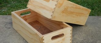
Structurally, a homemade sawing table looks quite simple. The machine consists of a supporting frame for mounting the motor, a transmission unit and a work table with a slot for the cutting disk. The design is equipped with stops for guiding the workpiece and a protective screen that prevents chips from entering and also increases work safety.
Mandatory requirements for a sawing table:
- rigid, stable design;
- smooth surface of the tabletop;
- secure disk mounting;
- fencing protecting the operator of the machine (table);
- easy access to the control device (start and stop buttons).
The equipment must be installed on a frame supported not on solid sheets, but on legs. This improves ease of use, although it makes the saw table less stable. To increase durability, the frame can be made of metal or reinforced with metal elements. Safety is ensured not only by the protective screen, but also by securing the disk from the bottom (inner) side. Additional requirements depend on the specifics of the work - auxiliary elements help to process parts more accurately, saw longer boards, as well as thick logs.
By making a saw table with your own hands, you can get a number of advantages - from reduced costs to the ability to change the design as the master needs it. If desired, you can replace some of the parts with more economical ones, or use materials left over from repairs or construction. The only disadvantage of a circular saw independently fixed to the machine is a decrease in the accuracy of workpiece positioning. But this moment still largely depends on the skill of the performer himself.
Rigid, stable construction
Smooth countertop surface
Secure disk mounting
Guard protecting the operator of the machine (table)
Desktop device
A table for a hand-held cutting circular saw should be a comfortable, reliable and safe workplace. To do this, he must meet the following requirements:
- Stable and rigid design;
- flat and smooth surface;
- fixing the legs in the ground;
- have a place for wood waste;
- be equipped with protective shields.
If the cutting table for a circular saw meets these simple five requirements, then the design will truly perform all its functions.
The machine must also meet certain requirements (after installing the saw on the table):
- High-quality fastening of the saw blade;
- the presence of protective walls that cover the cutting part;
- convenient location of the on/off button.
The more carpentry experience, the better the structure can be built. By choosing the right table dimensions, you will be able to better perform tasks on it in the future. Whether it will be possible to cut long boards and process workpieces depends only on the drawings and the execution of the work.
Materials
When assembling a cutting table from chipboard with your own hands, you should maintain an optimal balance between functionality, safety, time and money. This can be achieved by selecting parts and materials with the necessary parameters. It is possible to reduce costs by using old parts of other structures - furniture, frames of wooden houses and outbuildings.
Tabletop
The main requirements for a saw table are resistance to heavy loads, shocks and vibration. The tabletop must be smooth enough to move and not bend under a weight of 50 kg or more. Suitable options might be:
- Metal (steel or duralumin) 3–5 mm thick. The advantages of metal countertops are high strength, almost unlimited service life, the disadvantages are heavy weight, decent cost.
- Laminated chipboard or moisture-resistant plywood with a thickness of at least 2 cm. The cost of this option will be the most profitable, but the strength is noticeably reduced.
- Textolite 15–20 mm thick. The material is more durable than plywood, but inferior to metal. In terms of cost, textolite countertops are also between metal and plywood sheets.
Plastic, chipboard or OSB are not recommended as countertop materials. A structure made from this raw material will be unstable to vibration from the saw. It is possible to make a table entirely from natural wood, but it is too expensive.
You can reduce costs while increasing strength by using combinations of materials—for example, thick plywood covered with sheet metal.
Metal
laminated chipboard
Textolite
bed
At the base of the table for sawing boards there can be wooden beams, secured under the lid to increase rigidity. Elements with a cross-section of at least 5 x 5 cm are placed at a distance of 50–90 mm from the edge of the tabletop. For the sawing table, it is recommended to choose bars made of hard wood - beech, hornbeam, oak. The advantages of wood are low cost, easy installation using self-tapping screws. Disadvantages - less strength and service life, high probability of fire.
The upper part of the table frame for cutting chipboard and other materials is often made by hand from the same sheets that were chosen for the table top. For the legs of a wooden structure, it is recommended to use timber, securing it with metal corners. The pros and cons of wooden supports are similar to the features of a frame made of the same material.
The basis of the table for cutting and sawing boards can be metal. Stability increases when choosing metal corners or channels with sides of 25–50 mm. To save money, they are purchased at scrap metal collection points or replaced with profile pipes. The frame parts are connected by welding. The use of bolted connections is not recommended due to the possibility of loosening due to vibration. The reasons for choosing a metal frame are maximum strength, reliability, and easy maintenance. Disadvantages: high cost, need to use a welding machine.
Metal
Wooden beams
Plywood
laminated chipboard
DIY amateur sawing table
Good afternoon everyone! During the discussion of one of my reviews, in the comments the participants were asked to review the sawing table on which I work. In this review, I will tell you how I whipped up a sawing table, using what I had, plus some that I bought as small items. A detailed SketchUp model of the table, with all elements and components, is attached to the review. I had been thinking about a sawing table for a long time, but there were a huge number of other things to do, and, naturally, it was put off until better times. Then, when last year had a relatively calm winter, I came across a series of videos on homemade saw tables and realized that this was something that was time to do.
In so many video reviews, tables are made so seriously, and always against the backdrop of fully equipped workshops with a bunch of machines, that sometimes you look at your working conditions and doubt whether to take it. In this review, I will tell you how I made a table in fairly spartan conditions, having in my hands a circular saw, an angle grinder, a screwdriver and a router (it was here that the router, which had been lying new in the box for three years, was tested for the first time).
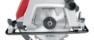
I had a Hitachi C6SS hand-held circular saw, a cheap one, but as it turned out, a very reliable machine that had survived and completed such a volume of work at a construction site that it was time to put it on a pedestal and in a prominent place in the workshop. But since any tool must work to the end, she was offered a new place.
After completing the main stage of building the house, I was left with a whole sheet of 21 mm plywood (FC 4/4), which had stood alone for 3 years, and it was time to adapt it somewhere. At that moment, I did not make a separate project for the table, the whole idea and idea, as I see it, formed in my head, so I did it right on the spot, and the main components and materials were selected for the implementation process, I ran my eyes through what was lying in the pantry, workshop , in boxes with hardware and fasteners and other small things. Accordingly, no modeling was done, but for this review I transferred the desktop into a 3D model in SketchUp, tried to represent all the component elements, the only thing I didn’t draw was the nuts and screws, it was too lazy, and it seemed like a waste of time to me , since it’s clear in principle and, if anything, I’ll explain as the review progresses. The model shows how and what is assembled; you can remove the enlarged elements layer by layer; perhaps this model will be useful for someone to repeat or as an idea for its implementation.
Model of a saw table in SketchUp
And so, I took a sheet of 21 mm plywood, marked it out and cut out with a circular saw the base of the table with dimensions of 1100 mm x 820 mm. The dimensions of the table are large, but what was needed was a universal table on which you can saw both small parts and large-format sheet materials, plywood , laminated chipboard for cabinet furniture.
Then he turned the resulting sheet over, marked it, placed the circular saw with the blade raised on the sheet, traced the contour of the saw sole with a pencil, and used a router with a groove cutter to select the material in the resulting projection of the sole to a depth of about 12 mm. The circular saw blade is then inserted into the resulting recess. The handle and protective blade guard are first removed from the saw.
Along the contour of the saw sole, 4 holes were made in the table base sheet for M8 bolts. M8 mustache nuts were installed from the upper part of the base (reverse). The saw sole is installed in the recess and pressed through reinforced washers with M8 bolts to the base of the table.
Then we loosen the mechanism for adjusting the cutting depth of the saw, plug the saw into a socket and, pressing the saw, saw through the base of the table to the full depth; on the back (working) side of the table we have a disk. The most important point here is that when installing the saw in a recess, do not confuse its direction, in which direction the disk should rotate (the disk on the side of the working surface of the table should rotate toward itself), while I was trying it on, I almost got it wrong, but I noticed it in time. By the way, in the Sketchup model I used a saw from 3D Warehouse, and if you look at the photo of my table, the saw drives in the SketchUp model (Makita) and in real life (Hitachi) are mirrored, located on different sides of the saw. I found only this model of saw and left it, the main thing was to correctly indicate the direction of rotation of the blade. Everyone's saws are different anyway.
Already in this form on the table you can saw: - place the base of the table on chairs / stools / drawers (in the workshop I placed one side on the shelf of the rack, the other on the back of a chair against the wall); - relative to the saw blade, using a long ruler, draw the center line of the cut.; - we take a long aluminum angle (or a beam, or a flat board), place it along the square relative to the cutting line, fasten it to the table with clamps - and we have an improvised temporary parallel stop.
In this way, I further sawed all the other parts of the table while it was slowly assembled.
The first thing I decided to do was cut out the saw guard to remove dust. For the first time in my life, I was able to instantly, without adjustment, get completely identical parts, like twin brothers. The casing consists of four walls made of 10 mm plywood, the bottom is made of a piece of fiberboard. We glue everything together using PVA and self-tapping screws.
To connect the vacuum cleaner, I made a hole in the lower corner of the box with a bimetallic crown for a 50 mm sewer fitting. To attach the fitting to the body, I cut the edge of the fitting into sectors, inserted the fitting, heated the sectors and bent them to the wall of the box, then I went through each sector with small self-tapping screws, and filled the gaps on the reverse side with hot glue. It turned out strong, and careless movement of the vacuum cleaner hose will definitely not tear the fitting out of the body.
To attach the box to the table I used metal corners 30x30, as well as 15x30 for the lock. I made flat lugs from cut 6 mm plywood plates with a Dremel, glued them to the table, and inserted the corners of the box into them. On the other side of the box, a kind of lock is made using a metal plate and self-tapping screws.
We connect the vacuum cleaner, try it - all the dust is inside, it no longer flies into the face.
We cut out longitudinal stiffening ribs on the table and glue them to the base using PVA and self-tapping screws. We will further attach the guide profiles of the parallel stop to these same ribs.
Since the surface of the future table must be smooth for normal sliding of workpieces and materials, and FK 4/4 plywood does not in any way contribute to normal sliding, it was necessary to come up with something with a coating. In general, laminated plywood is usually used for such tables, but we only sell it in huge sheets, and the main idea was to use an existing sheet of plywood. Here, a large corporate advertising poster made of foamed PVC, 4 mm thick, printed on only one side, was successfully turned up; accordingly, the clean white reverse side was perfect as a facing material for the table.
I’ll say right away that foamed PVC is not the best material for such purposes. I don’t know how long it will last, but there are grooves and scratches on it from the sharp ends of the missing parts. While this is not critical, and may not be critical at all, it may be necessary to change it in the future, or cover it on top with a thin sheet of another material. A sheet of plexiglass would generally be suitable for these purposes, but it was not available.
For future carriages and pushers, it is necessary to install guides made of aluminum profiles in the form of a 15x10x1 channel into the base of the table. For installation in the base, transverse grooves for aluminum profiles were marked and made with a router and a groove cutter. Since there will be a 4 mm PVC sheet on top of the table, the depth of the groove is accordingly 6 mm.
I cut the PVC sheet into 3 parts, two parts to the left and right of the profiles, and one part between the profiles. When I put the profiles in the grooves, the following problem was identified, but rather it is called a jamb. Table base sheet with deflection! About 3 mm in the center of the sheet relative to the edges, I applied a meter steel ruler, everything is clearly visible. The sheet of plywood stood for three years in the boiler room, in a vertical position against the wall, although it may have originally been crooked. Out of resentment, I took an angle grinder and a flap wheel and went outside to fix the deflection by removing material around the edges. There was a bucket of dust. As long as I had the patience, I removed it, but the area is large. I decided to fix the rest of the deflection as follows. Since I planned to fasten both the aluminum profile and PVC sheets using MOMENT MV-100 liquid nails, I made a larger portion of glue in the central part of the sheet and grooves, with intervals for subsequent shrinkage during leveling. Apply glue evenly from the edges of the sheet. Then I put aluminum profiles in the grooves on the glue, and then all three sheets to the profiles. I took a long aluminum corner 40x40x2 and, moving across the table, began to level the height in the central part of the sheets and profiles relative to the edges. After passing the profile, I checked the gaps and evenness of the sheets in the transverse, longitudinal and diagonal directions - everything worked out. After hardening, MV-100 becomes like a stone, so the performance and rigidity of the table were not lost.
Next, it was necessary to make a parallel emphasis. An aluminum profile 40x40x2 (which I used earlier for leveling) was used as the main element of the stop. To improve the rigidity and weight of the stop structure, as well as ease of installation of subsequent parts, it was decided to glue a 30x30 wooden beam into the profile. I also glued it to MOMENT MV-100. Other parts of the stop were also made from a profile and glued double slats of plywood 40mm wide.
For transverse movement and fixation of the stop, a system was chosen from a C-shaped steel profile, sliders made from oak parquet boards and a square washer on a long M8 bolt. The bolt head was thoroughly ground, the square thick cast washer (from the beam fastening of the cable routes) had a recess into which the bolt head was recessed and seated with two-component epoxy glue.
On the back side of the bolt, which passes through the transverse clamping element of the stop, a round handle with an M8 mustache nut was installed (the handle was also made from plywood directly on the saw blade)
A square washer with sliders starts from the C-profile, relative to which the stop structure moves; when we tighten the handle of the stop, we press the square washer against the outer walls of the C-profile and fix the stop relative to the table. Also, the square washer prevents the bolt from turning in the profile when the handle is tightened.
I also placed a C-profile on the back side of the table, and I wanted to make a similar system, but I was afraid that the stop would jam too much when moving, and I needed fixation on the back side too, I needed the stop to be even with respect to the center line on both sides, and with fixation at only one point, it doesn’t always work out where it will be level, and in some position it will be +2-3 mm, the C-profile may not be ideal, although it looks smooth. A much simpler design was invented: at the bottom of the C-profile I placed a slider part with an M8 pin fixed in it, and through the intermediate element and the stop I drilled a hole and brought up the mating part of the pin, onto which I placed another handle with an M8 mustache nut. Now, by twisting the handle, I press the slider through the pin onto the C-profile and thus fix the far part of the stop relative to the table.
Working with the stop is as follows: - loosen both handles on the stop; — move the emphasis in the desired direction; — using a square, I measure the required distance from the stop to the center line of the cut at the bottom of the stop; — I fix the lower part with a handle; — I check the distance from the stop to the center line of the cut at the top of the stop; — I fix the upper part with a handle; - you can saw.
To work with parts and workpieces on the table, a simple carriage and a small pusher with guide sliders were made.
The design of the carriage and pusher is made from the remains of 16 mm laminated chipboard; the pusher also uses an aluminum profile 40x40x2. I made the sliders for the guides from oak, cutting thin slats from oak parquet boards. I glued the sliders to the carriages using PVA and additionally self-tapping screws. To improve the sliding of the oak slider in the aluminum channel guide, I impregnate the oak slats with aerosol silicone grease; the wood absorbs it and moves perfectly in the profile without biting.
The workshop space in the house is very small, so the table must be collapsible (not needed - disassembled), and portable so that it can be taken outside for work. Therefore, it was decided to make the table stands in the form of removable vertical frames with bevels. At the bottom of the table, in the form of plywood slats, mating parts with M8 mustache nuts were glued to fasten the stand frames to the table with bolts and washers.
To connect the saw electrically, I installed a socket right next to the saw; the standard power plug of the saw is plugged into it. I connected the socket from the contactor; the contactor is controlled by a block of START/STOP buttons installed on a separate plate on the front side of the table. The contactor is powered by a separate long cable to an outlet in the wall. The power button on the saw is secured with a tie.
To collect dust and sawdust with a vacuum cleaner, I also use a homemade cyclone made from a bucket, lid and sewer fittings:
What are the problems and what do I plan to improve:
— slight runout of the disk, I don’t quite understand yet, whether it’s a problem with the shaft, or with the disk itself (I use this one), but the distance between the center lines of the cut on both sides of the disk (cut width) is 4 mm. In principle, it’s not critical, we cut relative to the resulting cutting line, but I want everything to be even, I’ll try to replace the disk; — make a zero-gap liner from an aluminum sheet, although during the work I noticed that the formation of chips on the back side of the sawn sheet can be reduced if you reduce the height of the disc’s overhang, for example, make 15 mm for plywood 10 mm, you can see that the angle of the tooth coming out of the material changes significantly ; — make a device for adjusting the reach of the saw, I now set the reach height using a standard fixing mechanism, but for this you need to completely remove the box, which is not very convenient, you need to make a lift;
The table works very well, you can see what was done on it in my other reviews. For non-professional use it is quite enough. It was easy to do, quick, and the cost was low. Of course, there are much more advanced designs, but they require more time and money. If there are additional questions/criticism/comments/suggestions for improvement, then I think it will be useful for everyone, since comments on mysku are a great storehouse of knowledge.
Model of a saw table in SketchUp
Partner
Selection of dimensions
It is worth choosing the size of the sawing table depending on the square footage of the workshop. The small area of the room allows you to use a tabletop of 50 x 50 cm. Making the sawing table smaller does not make sense - it will be difficult to use it when processing long workpieces. The universal size, ensuring convenient sawing of laminated chipboards, is 80 x 80 cm.
The maximum recommended dimensions of the sawing machine are 120 x 120 cm.
To comply with safety requirements, it is recommended to place the saw in the middle of the tabletop at a distance of at least 25 cm from the edge - it is this indicator that leads to the minimum width of 500 mm. The location of the saw blade also depends on how it will be used. There are three types of design:
- for longitudinal sawing;
- for cross cutting;
- universal.
The depth and location of the disk installation depend on the workpieces processed on the machine. For boards and plywood, it should protrude above the tabletop by 50-80 mm, for logs - by 110-125 mm. The height of the upper part of the frame made of sheets of plywood or chipboard can be in the range of 35–40 cm. If you make the frame only from timber, this parameter depends on the cross-section. The remaining part of the structure consists of wooden legs, the size of which craftsmen usually choose to suit their height. The overall height of the sawing table is about 1.0–1.1 m, but can be reduced to 900 mm.
Advantages and disadvantages of making a circular table yourself
A table for a circular saw of your own production has a number of advantages over furniture made in a factory:
- financial savings - a finished machine costs 5-6 times more;
- small sizes;
- your table will be made in a single copy. This is a unique project;
- ease of operation in cases where it is necessary to cut materials of non-standard dimensions and shapes.
Disadvantages of self-assembly of a circular saw:
- drawing up a drawing is quite difficult. Alternative - find a ready-made solution on the Internet that suits your size;
- If the saw hole is made incorrectly, the unit will quickly become clogged. Difficult waste exit is a common mistake of inexperienced furniture assemblers;
- incorrect determination of the center of gravity will negatively affect the result of the master’s work.
Create a drawing
The first stage of creating a machine for processing wood is drawings of a sawing table. You don’t have to compile them by choosing the appropriate option on thematic sites or forums. But it’s better to make at least the simplest diagram yourself, taking into account the available materials and the selected sizes.
The drawing notes all the nuances that will be needed to prepare the materials, indicate the mounting locations for the supports and their angles of inclination if the table legs are not perpendicular to the table top. In the figure it is also worth noting the place for attaching the unit to turn the saw on and off. When drawing up a diagram yourself, maintaining scale and exact proportions is not necessary. The main thing is to correctly indicate the dimensions of all future parts for the sawing machine.
Preparing for work
Before you begin, you need to decide on the necessary set of tools and materials that will be needed during the work process.
The following tools will be used for work:
- A circular saw or you can use a jigsaw.
- Screwdriver.
- Grinding machine.
- Grinder (Angle grinder).
- Jigsaw.
- Hand tools: hammer, pencil, square.
During the work you will also need the following materials:
- Chipboard.
- Plywood.
- Solid pine.
- Steel tube with an internal diameter of 6-10 mm.
- Steel rod with an outer diameter of 6-10 mm.
- Two washers with an increased area and an internal diameter of 6-10 mm.
- Self-tapping screws.
- Wood glue.
Manufacturing stages
Before assembling the machine for cutting boards, logs and blanks, you should prepare all the necessary materials and tools. To work you will need:
- moisture-resistant plywood;
- sheet material suitable for making the body;
- elements for the body and legs (bars 40 by 40 mm).
Fastening will be done with self-tapping screws using a screwdriver. All necessary parts are cut with a jigsaw. A saw with a disk of suitable diameter is also prepared.
Algorithm for creating a table:
- Sawing all parts into pieces with the required dimensions.
- Marking the mounting areas for the saw and legs on the table top.
- Making a case, which is usually a rectangular box without a lid or bottom.
- Installation of countertops.
- Cutting a hole that should be 5–10 mm longer and 4–6 mm wider than the disc.
If you cut the material at a certain angle, the resulting slot should resemble a trapezoid (inverted) in shape. For smooth sawing, a regular hole is made. Before cutting out the groove, you should apply a saw and adjust the marks.
Sawing all parts into pieces with the required dimensions
Marking the mounting areas for the saw and legs on the tabletop
Case manufacturing
Installing the countertop and cutting the hole
Preparing to install the saw
Features of manufacturing a metal frame (bed)
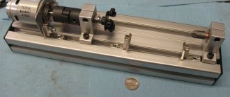
The upper part of the metal base is a welded frame measuring 800x800 mm with legs made of pipes 220 mm long and a cross-section of approximately 17-20 mm welded at the corners.
Two longitudinal profiles are mounted on a frame made of 25 mm angles, used to install the shaft on bearings.
To ensure greater stability of the structure, the lower part of the frame is welded from larger corners (40 mm) and has two jumpers intended for mounting the electric motor with starting equipment circuits. Pipes are also welded at its corners, having the same length as on the upper frame, but slightly larger in diameter (23-25mm).
Closer to the edge of such pipe legs, threaded holes are prepared in which special holders are located (they are also called “lambs”). With the help of these wings it will be possible to fix the position of the pipes of the upper part of the frame, which is moved to regulate the tension of the drive belt.
How to install the saw correctly
The next step is to properly position the saw on the top surface of the saw table. To do this, the contractor must perform the following actions:
- Install the tool so that its working part fits into the pre-prepared groove.
- Mark the locations for the M8 plowshare bolts with countersunk heads (they will be used to secure the saw blade).
- Drill the plywood from the top to make equal holes with a diameter of about 8 mm.
- Make a countersink to countersink the bolt heads.
- Carefully install the metal saw blade and carefully tighten the bolts from the bottom using nuts and lock washers.
The work of making a machine requires great concentration and concentration. The slightest mistake can lead to having to start all over again.
After securing the structure to the table, you need to install a block to turn the circular saw motor on and off. A hole is cut in the housing, the switch is secured with bolts and universal glue. There should be two separate cables coming from the unit. One to the instrument, the other to the nearest electrical outlet.
When assembling such a unit yourself, it is worth taking into account the performance of the motor, as well as the maximum power of the electric motor. In this case, experts advise choosing a motor whose power does not exceed 1000–1200 W, otherwise operation may be unsafe. And a more powerful saw means a heavier and more stable table.
Install the tool so that its working part fits into the pre-prepared groove
Mark the locations for the M8 countersunk plowshare bolts
Install the metal saw blade and carefully tighten the bolts from below
Install a block to turn the circular saw motor on and off
Pros and cons of a homemade circular saw table
You can make a table for a circular saw yourself, taking into account personal requirements and preferences. It will be as comfortable as possible to use. The table can be made in different sizes and heights.
There are models not only of the manual type, but also with the ability to be fixed on the table.
There are several main advantages:
- cost minimization;
- the ability to equip the structure with pushers and stops;
- ensuring maximum rigidity and stability.
Using a hand saw is not always comfortable; using a table allows you to make the sawing process smoother and more accurate.
The disadvantages of a homemade table for a circular saw include time costs. The master will need to study diagrams, drawings, prepare materials, and perform high-quality processing.
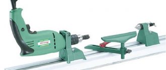
Making stops
The last stage of making a sawing table with your own hands is installing stops. A standard part of most circular saws is a rip guide. Traditionally, the stop is made from an aluminum cornice or a wooden block. Its size is chosen so that the part runs across the entire table - parallel to the saw and from edge to edge.
Cross stops are also often used on sawing tables. They are used to cut parts at an angle of 90 degrees and trim boards. To make a stop, follow these steps:
- Prepare an ordinary plywood sheet 1 cm thick.
- Secure a block at least 2 cm high to it.
- Attach a second rail perpendicular to the first on the bottom side of the base.
- Cut off excess base.
The transverse stops are attached to the workpieces using clamps or fastening devices made from wooden washers. Such homemade clamps provide fastening of guides to parts of almost any width. If you fix the block on the underside of the base at an angle of 45 degrees, you get a corner stop. After all work is completed, the surface of the circular table can be treated with a grinding machine and coated with a layer of protective varnish. This will protect it from various mechanical damage, and in general will extend its service life.
Perhaps such a table does not look as attractive in appearance as a factory one. However, from a technical point of view, it is in no way inferior to it, so even a novice carpenter can safely take on its manufacture.
Prepare parts for the longitudinal stop
Assemble mounting brackets
Place the bar on the table
Clamp the crosscut pieces together
Attach the cross supports using clamps
Cross stop is ready
Design of a circular saw stop
The entire structure consists of two main parts - longitudinal and transverse (meaning relative to the plane of the saw blade). Each of these parts is rigidly connected to the other and is a complex structure that includes a set of parts.
The main technological solution of this stop is the principle of jamming using an eccentric and tightly pressing two transverse guides with an oblique end.
Fixation occurs by turning the eccentric mechanism.
The pressing force is large enough to ensure the strength of the structure and securely fix the entire rip fence.
The entire design is not trivial and consists of a large number of different parts, each of which has its own purpose and size.
From a different angle.
The general composition of all parts is as follows:
- Transverse part
- The base of the transverse part;
- Upper transverse clamping bar (with an oblique end);
- Lower transverse clamping bar (with an oblique end);
- End (fixing) strip of the transverse part.
- Longitudinal part
- Planar sliding element (laminated chipboard, 2 pcs.);
- The base of the longitudinal part;
- Clamp
- Eccentric
- Eccentric handle
What do you need to buy?
Now the process of making the table itself begins. The pricing policy is quite modest due to the relative cheapness of the materials used. You, of course, can buy much more expensive ones, but this is not necessary due to the rapid wear and tear of this work area. It will be a big plus if you are good at working with wood. To create a homemade table you will need:
plywood sheet (approximately 800 by 800 mm, 10 mm thick); wooden blocks from 100 cm long (50 by 50 mm); necessary equipment (drill, screwdriver, jigsaw, etc.) 4 pcs. sheet material made of wood (for the body) 400 by 784 millimeters; ruler and pencil; clamps for working with wood; self-tapping screws, screws and bolts; plastic ties; 2 metal corners.
You may have to purchase additional building materials (if you want to add something of your own or upgrade your future homemade table).
Safety in use
Keep in mind that working with a circular saw is dangerous. In order to avoid injury during the work process, it is necessary to constantly monitor the position of the saw table, its strength and stability .
Each time, before turning on the equipment, check how firmly it is secured in place.
Attention : holding the cut material with your hands while the saw is running is strictly prohibited. Otherwise, your fingers may be damaged.
To prevent bouncing wood particles from getting into your eyes, it is recommended to wear safety glasses .
Tip : In the workshop you may also need a milling, welding or folding table, a simple table made of boards or pallets, and, of course, a personal tool cabinet.
Finishing
After manufacturing and assembling the circulation table, to simplify working moments, it is advisable to apply markings .
It is this that will make it easier to cut materials. To extend the life of the product and increase its aesthetics, a hand-made table can be primed and varnished . These manipulations will also prevent the lumber from sliding on the surface and protect the product from increased moisture.
Step-by-step manufacturing instructions
To make a table for a circular saw at home, you need to purchase the following tools:
- electric jigsaw;
- drill;
- screwdriver;
- milling machine;
- grinder;
- measuring instrument - tape measure, ruler, pencil.
Let's look at the order of assembling the structure using specific examples.
Lifting table for circular saw
Approximate design drawing - dimensions are selected individually:
Step-by-step instructions for assembling a table with a lifting mechanism made of wooden beams:
- Level the boards using a plane. Assemble the frame. Make holes with a diameter of 0.5 cm on 4 sides of the tabletop. Drill another through hole for the table legs;