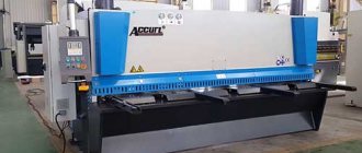
Guillotine, crank shears NK3418 are produced with automatic adjustment of the gap between the knives and a mechanized back stop, which allows you to set the specified size of the cut workpieces from the operator’s workplace using a digital counter installed on the front side of the shears. The series scissors are reliable, easy to use, and easy to repair. Provide high precision of cut workpieces and parts. The lubrication system and electrical equipment allow their operation in low temperature conditions, which is impossible when working on hydraulic shears. Due to the absence of oil leakage, as happens when working with hydraulic shears, the cleanliness of the working area of the shears is ensured.
NK3418 scissors are a new generation of scissors with a fundamentally new design and kinematic diagram. Purpose and scope of application: Crank sheet shears with an inclined knife NK3418 are designed for cutting sheet metal with a tensile strength of 500 MPa and a maximum cross-sectional size of 6.3x2000 mm. It is also possible to cut non-metallic sheet materials, eliminating the rapid dulling of the cutting edges of knives and cracking of the sheet being cut. Scissors are widely used in procurement shops of mechanical engineering enterprises, automotive and tractor manufacturing, aircraft manufacturing, shipbuilding, agricultural machinery and other industries, as they have higher productivity than shears of the “ND” series, due to the lack of preparatory time for readjusting the cutting mechanism for different thicknesses of the metal being cut and mechanization of the back stop.
- Guillotine shears NK 3418 are designed for cutting sheet metal into strips.
- NK3418 shears are intended for use in various industries where sheet metal is cut.
- Scissors NK3418 are supplied in climatic version UHL4 according to TU 3828-012-69398252-2012.
Information about the manufacturer of guillotine shears NK3418
The manufacturer of NK3418 scissors is the Stryi Forging and Press Equipment Plant .
Currently produced by PJSC Kuvandyksky, Orenburg region, Kuvandyk
Machine tools produced by Stryisky KPO plant
- ND3314g
crank sheet guillotine shears 1600 x 2.5 - ND3316g
crank sheet guillotine shears 2000 x 4.0 - ND3318g
crank sheet guillotine shears 2000 x 6.3 - NK3416
– crank sheet guillotine shears 2000 x 4.0 - NK3418
- guillotine sheet crank shears 2000 x 6.3
Hydraulic diagram of guillotine shears H3222. Hydraulic pump (Fig. 15,16)
Hydraulic diagram of guillotine shears N3222
In the assembly housing containing cylinder 1 and tank 2, there is a piston group, including piston 3 and piston 4, driven by a cam 5 mounted on the crankshaft, 1 through a roller 6 and a block 7, mounted on a swing arm 8. The return of the pistons is achieved by a spring. 9.
The cavity of the larger piston 3 is protected by two pressure valves 10, which control the pressure from the piston 4 line. The cavity of the piston 4 is protected by safety valve II with spring adjustment 12. Oil suction by the pistons is ensured by the return of the clamps and the check valve 13.
Check valve 14 allows you to apply clamps to the sheet being cut using both pistons. Pressure control in the cavities of pistons 3 and 4 is achieved, respectively, by 15 and 16 nanometers, connected through chokes 17 and valves 18 to turn off the pressure gauges after measurement.
The operation of the hydraulic system is illustrated by a hydraulic diagram (Fig. 16). The rotation of the cam 5 with the crankshaft of the machine through the roller 6 and the block 7 causes the movement of the pistons 3 and 4, which together direct the oil into the line of the clamps 19. The pressure spools 10 are locked until the clamps touch the sheet. Then the pressure in the clamp line quickly increases and causes the spool valves 10 to open and the piston cavity 3 to communicate with the tank.
Valve 14 closes and pressure is maintained only by piston 4. Excess oil under pressure opens safety valve II and drains into the tank. After cutting the sheet, cam 5 releases the pistons and the pressure drops.
Piston 4 receives oil supplied by the clamps from the return springs, and piston 3 receives oil from the tank through check valve 13. Holes “a” located on piston 4 open when all the oil from the clamps has entered the cavity of piston 4 and then the cavity is filled through check valve 13.
The hydraulic system is filled with oil at idle speed of the scissors with valve 20 open. At the same time, the flow of oil from the clamp line into the tank is monitored. When oil flows out without air and foam within 5-10 strokes of the slider, the scissors are stopped and valve 20 is closed. The hydraulic system is full.
Specification of components of scissors NK3418
| № | Parameter name | NK3414 | NK3416 | NK3418 |
| 1 | Remote Control | NK3418-93-001 | NK3418-93-001 | NK3418-93-001 |
| 2 | Side support | ND3316G-35-001 | ND3316G-35-001 | ND3316G-35-001 |
| 3 | Side support | ND3316G-35A-001 | ND3316G-35A-001 | ND3316G-35A-001 |
| 4 | Knife beam holding mechanism | NK3414-75-091 | NK3416-75-001 | NK3418-75-001 |
| 5 | Knife beam position indicator | NK3414-74-001 | NK3416-74-001 | NK3418-74-001 |
| 6 | Lighting | NK3418-76-001 | NK3418-76-001 | NK3418-76-001 |
| 7 | Corner stop | NK3418-37-001 | NK3418-37-001 | NK3418-37-001 |
| 8 | Rear stop | NK3414-34-001 | NK3416-34-001 | NK3418-34-001 |
| 9 | Cutting mechanism | NK3414-31-001 | NK3416-31-001 | NK3418-31-001 |
| 10 | Back gauge sensors | NK3418-39-001 | NK3418-39-001 | NK3418-39-001 |
| 11 | Sheet support | NK3414-38-001 | NK3418-38-001 | NK3418-38-001 |
| 12 | Backgauge drive | NK3414-24-001 | NK3416-24-001 | NK3418-24-001 |
| 13 | Lattice | NK3414-72-001 | NK3416-72-001 | NK3418-72-001 |
| 14 | Front stop | NK3418-36-001 | NK3418-36-001 | NK3418-36-001 |
| 15 | Lubrication | NK3414-81-001 | NK3416-81-001 | NK3418-81-001 |
| 16 | bed | NK3414-11-001 | NK3416-11-001 | NK3418-11-001 |
| 17 | Pneumatic equipment | NK3414-41-001 | NK3416-41-001 | NK3418-41-001 |
| 18 | Drive unit | NK3414-21-001 | NK3416-21-001 | NK3418-21-001 |
| 19 | Installation of clutch-brake | NK3414-23-001 | NK3416-23-001 | NK3418-23-001 |
| 20 | Gearbox | NK3414-22-001 | NK3416-22-001 | NK3418-22-001 |
| 21 | Electrical equipment | NK3414-91-001 | NK3416-91-001 | NK3418-91-001 |
Pneumatic schematic diagram of guillotine shears ND3316g
Pneumatic diagram of guillotine shears ND3316g
Air duct
The air pipeline (Fig. 23, 24) consists of a pneumatic block 1, a coupler-receiver 2, an oil sprayer 3 and a three-way double interlocked valve 4, connected by communication lines with a clutch-brake.
The three-way double interlocking valve (Fig. 25) is a dual valve with servo control from electro-pneumatic switching valves of the BB-32 type. The valve design is normally closed, i.e. when the solenoid coils of the switching valves are de-energized, the passage through the valve is closed. To turn on the valve, voltage is applied to the windings of the magnet coils of the BB-32 switching valves, while the valve valve connects cavity 1, permanently connected to the scissors receiver, with cavity IV. Compressed air supplied to the switching valves passes through the filter 9. Under the pressure of the compressed air, the pistons 6 rise upward, compressing the springs 4, previously reducing the (live) cross-section, blocking the exhaust openings. At the same time, at the end of the stroke of rod 7, valves 2 rise, compressing springs 1. Cavities I and II are connected. Cavity III is switched off, connecting the pneumatic network from the receiver to the pneumatic cylinder of the clutch-brake, and the clutch discs are turned on.
After removing the voltage from the windings of the electromagnet coils (disconnecting the clutch), valves BB-32 block the access of compressed air to cavity IV, simultaneously connecting it to the atmosphere. In this case, the pressure in cavity IV drops and the pistons 6 return to their original position under the action of springs 4, connecting cavity II with the atmosphere. Compressed air leaving the cavity passes through mufflers 8. At this time, springs 1 return valves 2 to their original position, blocking the access of compressed air from the receiver to the clutch-brake and valve (the clutch-brake is turned off). If, when the valve is turned on, one of the pistons (valves) does not turn on, compressed air from cavity II will enter the atmosphere through the gap between ring 5 and sleeve 3 - the brake clutch will not turn on. At the same time, the rocker arm will become skewed and press the microswitch, which will turn off the electrical control circuit of the press. If, during operation on single strokes, one of the electro-pneumatic control valves does not turn off (does not connect to the atmosphere), then the piston controlled by it will remain in the upper position, while the upper valve will be open and the lower one will be closed. The compressed air passed by the top valve will flow through the open bottom valve of the other piston into the atmosphere. In this case, the rocker arm will also become distorted and turn off the electrical control circuit.
Control panel for guillotine shears NK3418
Control panel for guillotine shears NK3418
List of controls on the remote control of scissors NK3418
- Switch - turn off the cutting line lighting
- Starting the main motor
- Manual clutch-brake control
- Stop automatic moves
- Turning on the rear support drive backwards
- Engaging the rear gauge forward drive
- General stop
- Handwheel for manual rotation of the rear stop drive
- Eccentric for setting the initial gap between the knives
- Electric scissor control pedal
- Control switch
- Operating mode switch
- Introductory machine
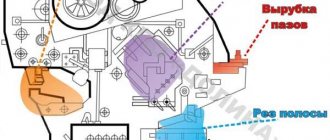
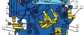
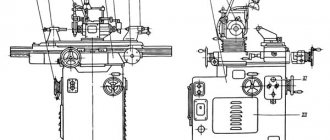
Description of the kinematic diagram of NK3418 scissors
The design of guillotine shears NK3418 includes three kinematic assembly units that have individual motion drives and autonomous control:
- main kinematic chain
- back stop
- thin sheet support
The main kinematic chain consists of an electric motor 1 (Ml), a V-belt transmission connected to the flywheel 2 and through a brake clutch 3 to the input shaft of a two-stage spur gearbox 4. The output wheel of the gearbox is rigidly connected to the eccentric shaft 5, on which connecting rods are mounted through levers 7, 8 , interacting with the pressure beam 9 and the knife beam 10. The knife beam is mounted in straight guides. The levers 7, 8 together with the pressure beam 9 and the knife beam 10 form a separate assembly unit (cutting mechanism) hinged in the frame on eccentric axes 11.
When the electric motor M1 and the brake clutch 3 are turned on, the cutting mechanism moves along path A (Fig. 7) as a single unit, rotating around axes 11 (see Fig. 6), until the pressure beam comes into contact with the sheet being cut (or the table if there is no sheet) . After the pressure beam stops, the knife beam from point B (Fig. 7) begins a linear movement along the guides. In this case, depending on the thickness of the sheet being cut, the required gap is automatically set between the knives. So, when cutting a sheet of thickness “t”, the gap between the knives will be A. When cutting a sheet of greater thickness t1 > t, the pressure beam will stop from the table surface above and, accordingly, the knife beam will begin linear movement from point C. The gap between the knives will be equal to A1 and A1 > A. For every millimeter of sheet thickness, the increase in the gap is ~ 0.04–0.05 mm.
If there is no sheet, set the gap between the knives using axes 11 to 0.02-0.03 mm (Fig. 6).
When the upper movable knife meets the sheet (start of cutting), the force increases, part of which is transmitted through the lever system to the pressure beam, providing a clamping force of 25% of the cutting force,
The kinematic chain of the back stop includes an electric motor 12 (M2), connected by a V-belt drive to the high-speed shaft of a worm gearbox 13. Two sprockets 14, 15 are mounted on the low-speed gearbox shaft
The first one is connected by a chain transmission to the indicator of the width of the cut strip 16, and the second is also connected by a chain to the shaft 17, through two pairs of bevel gears 18 driving the lead screws 19 into rotation, with which the thrust beam 20 is kinematically connected, moving when the screws rotate. To accurately install the beam 20 to the size of the cut strip, manual rotation of the M2 electric motor shaft is provided using the handwheel 21 through the cardan transmission 22
Thin sheet support . The support mechanism is designed to support the cut part of the sheet in order to obtain more accurate workpieces due to the sagging of the sheet when working with the back stop.
Purpose and scope
Model NK3418 crank sheet shears, which have an inclined knife, are used for cold cutting of sheet metal. An important property of each material is its strength. A high strength index brings limitations in the use of equipment. NK3418 shears can be used exclusively for cutting the following sheet metal:
- with a strength index of no more than 500 MPa;
- with a cross-sectional size of 2.5x1600, 4.0x2000, 6.3x2000 millimeters. the first value determines the thickness of the sheet, the second - the length of the cross section.
In some cases, such equipment can be used when cutting not only metal, but also other types of material.
Similar application features determine the scope of use of the NK3418 model:
- Procurement shops of enterprises associated with the fields of mechanical engineering, shipbuilding, aircraft manufacturing, and so on. In such areas of activity, NK3418 scissors allow you to quickly change the dimensions of sheet metal, which is the main material.
- Another area of activity in which the use of sheet metal is carried out. The characteristics of the NK3418 model determine the high performance of this equipment.
High productivity is primarily due to the absence of the need for readjustment. Guillotine shears can be used to cut metal of any thickness, within the established limit, without readjustment.
Download the passport of the guillotine NK3418
Another important point is that the NK3418 scissors have a mechanized back stop. This point determines that the guillotine is controlled using a special operator unit, which is used to set the size of the workpiece.
All guillotine shears of the NK model, including NK3418, have high operational reliability. At the same time, you should not forget about the ease of use, as well as the absence of difficulties at the time of repair work. The use of modern technologies allows us to achieve high cutting accuracy. The guillotine has a perfect lubrication system, as well as electrical equipment, which allows the machine to be used in difficult operating conditions. In comparison with hydraulic shears NK3418, the design option under consideration has a huge number of advantages.
Another important operational characteristic is the absence of oil in the cutting zone. This moment determines the cleanliness of the workpiece after cutting.
Electrical equipment for guillotine shears NK3418. General information
The following main electrical equipment is installed on the NK3418 scissors:
- M1 - main drive electric motor;
- MZ - Electric motor for rear stop drive;
The following voltage values are applied to the shears:
- Type of supply current: three-phase alternating
- Power circuit voltage 380 V
- Frequency 50 Hz
Control voltage:
- AC 110V
- DC 24 V
- Alarm circuit voltage 24 V
- Cutting line lighting circuits 24 V
#
#
All from the ruble!
- Why register?
- How to buy?
- How to sell?
- FAQ
Basket
Sell
Registration Recent
- Lots
Sections Searches Favorites
- Lots
Sections Searches
- Recent
- Lots
- Sections
- Search
Favorites
Lots Sections Searches Buying Bargaining now I bought Didn't buy Subscribe to new lots Requests for lots from sellers Sellers' offers Selling Transactions Completed auctions Top up account Demand Seller settings My store Activation Settings
Bargaining now I bought Subscription to new lots Requests for lots from sellers Sellers' offers Selling Sell On sale Transactions Completed auctions Top up your account Demand Seller settings
ListGallery
No items were found that matched your request.
Start from the first page of the site. Lots for all regions
| Frequently asked questions and support |
| Terms of Use | Sell | Registration | Open your auction | Affiliate program | Profile | Help All rights reserved 1999 - 2022. Old man |
Drawing of a knife for guillotine shears NK3418
Drawing of a knife for guillotine shears nk3418
Knife for guillotine shears 16 x 60 x 540
- HRC 54…58
- It is allowed to manufacture knives from steel grades 5ХВ2С and 6ХС according to GOST 5950-73
- Tolerance field for the thickness and width of a set of knives according to hll
- The permissible difference in the sizes of the set knives at the junction is no more than 0.03 mm
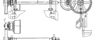
Knife beam of guillotine shears H3222 (Fig. 
Knife beam of guillotine shears N3222
It is a welded rigid structure of the slider 1 with a crankshaft 2, a connecting rod 3 and a device 4 for adjusting the slider in height.
A set of knives 5 in the amount of three pieces, identical to the fixed knives on the frame, is attached to the lower edge of the slide with special screws. To prevent wear of the slider in the part due to cutting forces, the knives rest on spacers 6. The spacers are replaced to compensate for the size of the knives during regrinding. Longitudinal displacement of the knives during cutting is prevented by a special stop.
The crankshaft 2, mounted in sliding frames 7 and 8, enclosed in axle boxes mounted on the frame struts, is connected to the slider 1 by connecting rods 3, which contain sliding bearings 9, covering the eccentrics of the crankshaft, and bearings 10, covering the eccentrics 11 of the slider adjustment device in height.
The eccentrics 11 are firmly connected to the slider 1 by means of housings and gears are connected to the adjusting roller 4. The eccentrics are locked from rotation by gear clamps 12.
To connect the balancers, the slider brackets 1 have holes with plain bearings 13.
The crankshaft has additional supports 14, in the form of semi-sliding bearings on the frame brackets, which reduces the bending of the shaft from cutting forces.
To remove the back stop from the sheet, a bracket 15 with guides for the stop roller is attached to the slide. The direction of movement of the knife beam relative to the vertical of the stationary knives is 3°, allowing the use of knives with mutually perpendicular sharpening planes.
To facilitate the change and reinstallation of knives, threaded holes are provided on the lower edge of the slide for attaching a special strip that supports the knives to be removed. The plank is manufactured by the consumer enterprise if necessary.
Technical characteristics of guillotine shears NK3418
| Parameter name | NK3414 | NK3416 | NK3418 |
| Basic parameters of scissors | |||
| Maximum thickness of the cut sheet at σ BP 50 kg/mm 2, mm | 2,5 | 4,0 | 6,3 |
| Maximum length of cut sheets in mm, mm | 1600 | 2000 | 2000 |
| The number of knife strokes per minute is not less than | 68 | 68 | 60 |
| Angle of inclination of the moving knife in degrees | 1°30′ | 1°30′ | 1°30′ |
| Width of cut sheet at back stop, mm | 700 | 700 | 700 |
| Number of knife cutting edges | |||
| Distance from the stationary knife to the frame (reach), mm | No | No | No |
| Clear distance between posts, mm | |||
| Table height above floor level, mm | 920 | 920 | 920 |
| Maximum cutting force, kN | 34 | 78 | 175 |
| Clamping force, kN | |||
| Operating modes | |||
| Brake type | |||
| Clutch-brake type | UV3132 | UV3132 | UV3132 |
| Electrical equipment | |||
| Number of electric motors | 2 | 2 | 2 |
| Electric motor, kW | 3,2 | 5,6 | 8,5 |
| Electric motor for back stop drive, kW | 0,37 | 0,37 | 0,37 |
| Total power of electric motors, kW | 5,57 | 5,97 | 8,87 |
| Dimensions and weight of scissors | |||
| Dimensions of scissors (length x width x height), mm | 2150 x 1475 x 1375 | 2610 x 1600 x 1510 | 2780 x 1600 x 1620 |
| Weight of scissors, kg | 1800 | 2870 | 4250 |
Related Links. Additional Information
- Manufacturers of forging and pressing equipment in Russia
- Classification and designation of hydraulic and crank presses
- Mechanical presses
- Hydraulic presses
- Automatic forging and pressing machines
- Bending and straightening machines
- Guillotine shears, press shears
- Hammers
- Repair of hydraulic systems of metal-cutting machines
- Designations of hydraulic circuits of metal-cutting machines
- Repair of gear hydraulic pumps
Home About the company News Articles Price list Contacts Reference information Interesting video KPO woodworking machines Manufacturers
Technical specifications
When choosing equipment, you should pay attention to the technical characteristics. These include:
- The maximum sheet metal thickness is 6.3 millimeters.
- The maximum width of the sheet to be cut is 2,000 millimeters.
- The maximum sheet length to the stop is 1,000 millimeters.
- The power of the installed engine is 8.5 kW.
- NK3419 scissors have a mass of 4250 kilograms.
The above points determine the possibility of using the equipment in different situations.