Press scissors NG 5223
are capable of developing a force of up to 63 tons during operation and are equipped with four functional sections, which allows them to perform the following operations:
- cutting round bars with a diameter of up to 50 mm, 90° angles with maximum dimensions up to 125x125x14 mm, 45° angles with maximum dimensions up to 100x100x10 mm, as well as shaped profiles up to No. 18A;
- cutting strips up to 190 mm wide and up to 18 mm thick;
- punching holes with a diameter of up to 30 mm in metal up to 16 mm thick;
- cutting open grooves with maximum dimensions of 80x65x10 mm.
The machine can be controlled either by push-button or pedal and is designed for three operating modes:
- single tool stroke;
- continuous running;
- manual rotation.
Equipment.
In addition to the standard equipment, it is possible to supply, for an additional fee, equipment that allows you to cut at right angles a corner of 160x160x12 mm, a channel of profiles 5-18U, an I-beam of 10-18 profiles and increase the length of the workpiece when cutting is carried out along the back stop, from 70 to 100 mm. In this case, the stop is also supplied at an additional cost.
Information about the manufacturer of press shears NG5223
The manufacturer and developer of the NG5223 press shears is the Kuvandyk plant of forging and pressing equipment "Dolina" , founded in 1941.
Earlier analogues of press shears were shears НВ5221, НВ5222, НБ5224.
Machines produced by the Kuvandyk Forging and Pressing Equipment Plant
- GD-162
- straightening machine for cutting reinforcing steel, Ø 16 - Н5222А
– combined shear press, Ø 45 - NB5222
– combined shear press, Ø 50 - NB5224
– combined shear press, Ø 67 - HB5221
– combined shear press, Ø 45 - HB5222
– combined shear press, Ø 50 - NG5222
– combined shear press, Ø 45 - NG5223
– combined shear press, Ø 50 - NG5224
– combined shear press, Ø 67
NG5223 Combined press shears. Purpose and scope
Combined press shears NG5223 are used for cutting strip, long and shaped rolled products and punching holes in sheet, strip and shaped rolled products, as well as for performing notching operations.
Press shears NG5223 can be used in machine-building, repair and other factories, when operating in climate zones with moderate and cold climates, version UHL, in dry and humid tropical climates - version O, placement category 4 according to GOST 15150-69.
Scissors model NG5223 , equipped with special devices and tools, can be used for bending and cutting operations, cutting and drawing blinds and for step-by-step punching of holes. With special knives in the sheet section, press shears can be used to cut strips of steel without “saber-shaped” deformations.
The frame is welded.
The slider of the section sheet , connected through a connecting rod to the eccentric shaft, makes a rocking motion, due to which the cutting work is carried out. Movable plate knives, a guillotine knife and a notching knife are attached to it.
The slider of the hole-punching section makes a reciprocating movement when punching holes.
The shears are driven from an electric motor through a belt drive to the flywheel. The movement is then transmitted through a two-stage gear transmission to the eccentric shaft.
Coupling with rotary key , band brake.
To prevent shifting of the material being cut, the scissors have clamps, and stops for cutting dimensional workpieces.
The electrical circuit ensures the operation of the scissors in single and automatic strokes.
Push-button and pedal controls.
Adjustment and adjustment of press shears HB5223
During the operation of the HB5223 press shears, it becomes necessary to regulate individual components to restore their normal operation. If belts slip over time, it is necessary to check their tension and, if necessary, tighten them. Set the normal belt tension using the adjusting screw.
During operation, due to wear of the textolite guides, it becomes necessary to regulate the gap between the guides and the slider of the sheet section. The gap is adjusted using six adjusting screws located on the rear and front walls of the frame. At the same time, the gap of the sheet shears can be adjusted using the slider guides. Adjust the gap between the knife plates of the shaped section using a set of shims installed under the L-shaped clamps. To obtain a normal gap between the guides and the punching press slide, a cast iron bar and spacers are used. Adjust the gap using three screws.
Maintenance of press shears HB5223
Every day before work you must:
- inspect and wipe the press shears НВ5223;
- check the reliability of the tool fastening;
- check the condition of the cutting edges of the tool. It is prohibited to work with chipped and dull knives, as this can lead to tool breakage and injury, as well as overload;
- Lubricate the shear press according to the lubrication diagram. Upon completion of work, turn off the power to the shear presses, inspect and wipe them thoroughly.
Once a week, it is necessary to blow through the internal cavity of the frame under the sheet slide with compressed air to remove accumulated scale.
Annually test the insulation of electrical equipment, switching wiring and test protective grounding, repair electrical equipment and grounding.
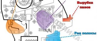
NG5223 Types of operations of combined shear presses
NG5223 shear press , combined with four working zones, allows you to perform several types of operations on one machine without preliminary reconfiguration of the shears, in any sequence and without changing tools, which ensures flexible and economical processing of rolled products, both in large engineering production and in any repair shop .
- Section for cutting long products - a section of an angle, a circle, a channel, an I-beam, a shaft profile. Cutting rolled products without marking up to 1000 mm along the stop
- Strip, sheet cutting section - strip cutting is carried out at different angles
- Punching section - punching holes of round, rectangular, square and any other shape in sheet and shaped rolled products
- Grooving section - punching open triangular and rectangular grooves
To facilitate the movement of long and shaped rolled products when feeding them into the working area of the shears, it is possible to use a roller table module of the MRPZ drive model.
The design of the shear press and many options for additional equipment allow the shear press to be used for processing rolled products of various profiles and different parameters.
To facilitate the movement of strip, long and shaped products when feeding them into the working area of the shears, it is possible to use a roller conveyor module of the MRP drive model.
Safety precautions when working with press shears HB5223
In order to increase safety measures for operating personnel, the HB5223 press shears are equipped with a mode switch and a control circuit switch located on the electrical cabinet.
During long breaks in work and after the end of the shift, the control circuit and the input circuit breaker are turned off. Maintenance of the electrical equipment of the shear press is carried out by electrical technical personnel. It is strictly forbidden to work on the shear press if the locking is faulty.
The installation of the modes is carried out by the service technician. After each switch, the switch handle is removed and kept by the service technician. If the electrical equipment is faulty, the worker must stop the shear press, turn off the input circuit breaker and call an electrician.
Prohibited:
- Cut and punch holes in profiles and materials larger than those indicated in the technical data.
- Work with the guard removed.
- Work on the sheet section without clamps.
- Feed material from the side opposite to the location of the control panels.
- Clean and wipe the press shears as you go.
- Adjust the shear press while the flywheel is rotating.
- Correct the position of the workpiece after pressing the pedal or lever.
- Cut a strip whose surface is covered with oil stains.
- Operate with the balancer switch unadjusted.
- Carry out adjustments with the electric motor turned on. The electrical equipment of the shear press must be reliably grounded and connected to a common grounded circuit. For this purpose, there is a terminal and a grounding bolt in the electrical cabinet and on the front of the frame.
- Work with chipped and dull knives.
NG5223 Components of combined shear presses
Location of the components of the shear press ng5223
NG5223 Specification of components and controls for combined shear presses
- General STOP
- Hole punching press - NG5223-3-001
- Punching press control
- Punching press table - NG5223-69-001
- Slider of the section sheet - НВ5222Б-31-001-А
- Signal lamp
- Input switch
- Electrical equipment - NG5223-91D-001
- Motor start button
- Switch for supplying voltage to the sheet section and the punching press
- Section table for cutting long products - NG5223-68-001
- Clamp - НВ5222-45А-001
- Pedal for switching on the sheet section
- Screw for fixing the stop of the sheet section
- Device for cutting channel and I-beams
- Channel cutting tool 5P, 6.5P, 8P
- Channel cutting tool 10P-18aP
- Special angle cutting tool
- Crankshaft
- Fencing - НВ5222-71Л-001
- Stop for cutting dimensional workpieces
- Device for punching holes at a certain pitch
- Device for punching rectangular grooves
- Bed - NG5223-11-001
- Drive - НВ5222Б-21-001
- Crankshaft - НВ5222Б-23-001
- Control of the leaf section - НВ5222-41-001
- Punching press control - НВ5222Б-42-001
- Centering mechanism - НВ5221Б-47-001
- Clamp of the sheet section - НВ5222-51-001
- Device for punching rectangular grooves - HP5222-53A-001
- Angle and circle cutting tool - НВ5222Б-61-001
- Sheet and notching tools - НВ5222-62А-001
- Lubricant - НВ5222-81А-001
Composition and delivery set of combined shear presses НВ5223
Main components of the combined shear press НВ5223
| Pos. in Fig. 1 | Name | Designation |
| 1 | bed | НВ5223-11-001 |
| 2 | Drive unit | НВ5223-21-001 |
| 3 | Section slider | НВ5223-31-001 |
| 4 | Crankshaft | НВ5223-23-001 |
| 5 | Punching slider | НВ5223-32-001 |
| 6 | Varietal Section Management | НВ5223-41А-001 |
| 7 | Punching press control | НВ5223-42-001 |
| 8 | Sheet section clamp | НВ5223-45А-001 |
| 9 | Centering mechanism | НВ5223-47-001 |
| 10 | Section clamp | НВ5223-51-001 |
| 11 | Angle and circle cutting tool | НВ5223-61-001 |
| 12 | Sheet and notching tools | НВ5223-62А-001 |
| 13 | Punching press table | НВ5223-69-001 |
| 14 | Fencing | НВ5223-71А-001 |
| 15 | Device for punching rectangular grooves | НВ5223-53А-001 |
| 16 | Electrical equipment | НВ5223-91-001 |
| 17 | Electrical cabinet | НВ5223-55-001 |
Controls of the combined shear press НВ5223
| Position in Fig.1 | Controls and their purpose |
| 9 | Centering mechanism handle |
| 18 | Pedal for turning on the hole-punching press and turning on the sheet, grade shears and scoring device. |
| 19 | Stop fixing screw |
| 20 | COMMON STOP button |
| 21 | COMMON STOP button |
| 22 | Eccentric axis for adjusting the slider position |
| 23 | Input switch |
NG5223 Kinematic diagram of combined shear presses
Kinematic diagram of press shears ng5223
The shear press is driven from electric motor 3 (Fig. 4) through a V-belt transmission, flywheel 2 and a single-stage gear transmission 1.4 to the eccentric shaft 6. Gear transmission 1.4 is straight-cut, cylindrical. The movement is transmitted to the slider 10 of the grade section through the connecting rod 5, and to the slider of the punching press 8 through the balancer 7 and the sinking stone.
Turning on and off . The actuators are turned on and off through a system of levers connected on one side to a connecting rod and a sinking stone, and on the other side to electromagnets 9.
Gear shaft 1 (Z1 = 14) has a rim width of 85 mm, made of steel 40X GOST 4543-71 (hardness HB 240... 260), wheel 4 (z2 = 126) - rim width 80 mm, made of steel 35L (GOST 977-88).
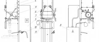
Design of the main components of the shear press ng5223
bed
The bed (Fig. 5) consists of two sheets - front 3 with a thickness of 50 mm and rear 7 with a thickness of 25 mm, welded together using spacers and ribs. The frame has borings for installing the axis 2 of the balancer swing, the axis 13 of the section slider, and the bronze bushing 12 for the gear shaft. In addition, windows 5 are made in the walls of the frame, into which stationary tool plates are inserted and secured using stops 4, 6. The gap between them is adjusted using liners 11, 10, which include gasket 9.
The knife 8 for cutting the strip is secured with screws in a special socket. On the side of the jaw, a strip 1 is welded to the frame, on which the press slide for punching holes is secured.
Section slider
The slider 1 (Fig. 6) of the section section is installed on the swing axis 11, secured by a bushing 9 in the bore of the frames (the axis is eccentric, which allows the windows of the slider and the frame to be aligned). The slider moves in textolite guides, with the help of which the gap between the movable and stationary knives is adjusted. The slider is connected to the eccentric shaft through a sinking connecting rod 2, which turns the section on and off, and a thrust bearing 6. To return the slider to the top dead center, a spring 5 and a rod 4 are used, and a screw 10 is used to stop the slider in the upper position. The movement of the balancer of the hole-punching section is transmitted by two brushes 3. The notching lever 8 is installed on the axis and connected to the slider through rod 7.
To reduce friction between the eccentric shaft and the liner 14, bronze liners 12, 13 are installed.
Punching press ram
Slider 3 (Fig. 7) of the press has a rectangular shape and performs a reciprocating movement. To obtain a normal gap between the guides and the slide, a cast iron strip and spacers are used. At the bottom of the slider, a punch 4 is fixed in the press table - a matrix. Stone 2, connected through an axis to an electromagnet, is attracted to balancer 5. The balancer presses on the stone and sets the slider in motion.
The punching operation is carried out. The return of the slider to its original position is carried out by a balancer through fist 6 and return spring 1. The centering mechanism allows the slider with the punch to be lowered to the intended location for punching the hole. The slider activation mechanism is controlled by a pedal.
Tool for cutting corners, circles, squares
The tool consists of a movable plate 5 (Fig. 8), a fixed plate 4, movable and fixed knives - plates 8 and 7 for cutting a circle into a square. A high-quality cutting stop 6 is installed on the movable plate, which is adjusted using oval grooves so that the workpiece fits snugly against the horizontal shelf of the stop. The movable plate is equipped with insert knives 9 and 10, the fixed one is equipped with knives 1, 2, 3 for cutting corners. Plate 5 and knife-plate 8 are installed in the socket of the section slider, plate 4 and knife-plate 7 are installed in the socket of the frame with fastening with L-shaped stops.
Sheet and notching tools
The tool consists of guillotine knives 1 (Fig. 9) for cutting rolled strips, a rectangular knife 2 and three fixed knives 3 for rectangular notching.
Channel and I-beam cutting tool
The tool consists of movable (Fig. 10) and fixed (Fig. 11) plates 4, equipped with knives, which change depending on the number of the channel and I-beam. The fixed plate is equipped with knives 1, 2, 3, 5, the movable one is equipped with three knives 1 ... 3.
Strip section clamp
The strip section clamp (Fig. 12) presses the strip when cutting to protect the worker’s hands from recoil impacts. The clamp is a bracket 6, bolted to the scissors frame. In the bore of the bracket there is an axis 8, on which the lever 7 and fist 1 are mounted. In the bore of the slider, an axis 3 is fixed, on which the rod 4 is mounted. The spring 5 is pre-tensioned with nuts 2. To the thickness of the rolled product being cut, the fist 1 is set by turning it by hand and locked with a lock 9 .
As the slider moves downwards, axis 3 and rod 4 compress spring 5. The spring presses on lever 7 and rotates it together with fist 1 until the fist touches the rolled product being cut. When cutting, the fist jams, thereby pinching the rolled product. After the cut, the fist returns to its original position.
Section clamp
The clamp of the section section (Fig. 13) is designed to protect the worker’s hands from recoil impacts. It consists of a clamp 1, which works similarly to the clamp of a strip section, but unlike it, the fist presses the rolled product through lever 2 and stop 3. The position of stop 3 is adjusted in the groove of lever 2 with a locking screw. Stop 4 serves as a lower support for the rolled product depending on the cutting angle of the rolled product (angle). The stop 4 moves along the rod 5 and is fixed by the locking device 6, while the mark on the lower part of the stop must coincide with the corresponding mark on the rod 5.
Round, hexagonal and square rolled products are fed into the holes of the stop 7. For unhindered feeding of rolled products into the middle hole, rod 5 is rotated to the upper position and fixed with screw 8 on the axis.
When replacing knife plates for cutting channels and I-beams, instead of stops 3 and 4, install a device for cutting channels and I-beams (NV5222B-52-001).
To punch holes on a hole-punching press without marking the centers of the holes, a table 8 (see Fig. 3) of the hole-punching press, which has movable stops, is provided. Mobile stops are installed on the table plate along two or three edges of the outer contour of the part and secured with crackers. The hole is being punched.
Table 34
The strip cutting table 34 allows cutting the strip at an angle.
The angle is set using a movable stop.
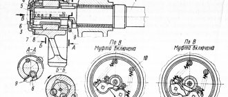
Crankshaft (Fig. 14).
Crankshaft 3 is installed in bronze bushings located: bushing 6 directly in the frame, bushing 4 in axlebox 2. Rotational moment is transmitted to the shaft from gear 1.
A cam 5 is installed on the shaft, turning the section section on and off.
Roller conveyor (Fig. 15).
The roller conveyor is designed for feeding long, strip and shaped products into the working area. The use of a roller table made it possible to increase the length of the workpiece when cutting to 3000 mm.
The assembly unit consists of a base 1, a holder 2, a roller 3. A stop 4 is installed on the roller table for cutting dimensional workpieces.
Setting up the shear press HB5223
- It is allowed to work with combined press shears HB5223 only after becoming familiar with the features of their maintenance, operation and safety measures. Before starting work, make sure the tool is reliable.
- When working with press shears НВ5223, to protect the operator’s hearing organs, it is necessary to use anti-noise headphones or anti-noise earplugs.
- After finishing work, turn off the power to the HB5223 press shears.
Features of the HB5223 press for punching holes
- Before starting work on the press, secure the punch and die in the appropriate sockets. Then, turning the handle of the centering mechanism, release the punch into the matrix and align the die holder body so that a uniform gap is maintained between the matrix and the punch. The gap is set depending on the thickness of the material being punched.
- After centering, return the handle to the upper position.
- After this, secure the matrix holder body to the frame and turn the gap again. Depending on the thickness of the material being punched, adjust the puller body with a gap of 1...2mm. from the plane of the sheet. Tighten the nuts and locknuts. Installing the puller body skewed is unacceptable.
- To punch holes along the cores, use the centering mechanism. Lower the punch with the handle and align the core on the workpiece with the punch core. Fix the workpiece and return the punch to its original position.
layout diagram of working places for press shears НВ5223
Features of the operation of the strip section of the NV5223 press shears
1. Before working on the section section, check the fastening of the knives to the knife plates and the fastening of the L-shaped adjusting clamps. The gap between the knives of the section section is set depending on the thickness of the material being cut and should not exceed 0.2...0.5 mm.
When replacing blade plates, remove the L-shaped tool clamps and remove the blade plates
2. To cut shaped steel, install the appropriate tool in the socket of the slider and frame. Align the stop plate to the appropriate angle (900 and 450) along the guide divisions and secure it. Install the stop and replaceable clamps. Insert the rental into the tool socket and align it according to the markings.
Press shears HB522 are equipped with automatic clamps.
When working with automatic clamping, due to the movement of the slider through a system of levers and springs, the force is transmitted to the fist and at the moment of cutting it fixes the workpiece, while before cutting the clamping lever must be in contact with the workpiece and be fixed by the hole on the cam. After the cut, the clamp automatically returns to its original position.
And all subsequent cycles are performed automatically.
Automatic clamps are made of high-quality structural steel that has undergone heat treatment. Automatic clamps are designed to protect the operator from impact when cutting workpieces.
Do not cut a strip that has oil stains on its surface. Cutting material with the tops of knives is not allowed. Adjust the gap between the knives using spacers under the supporting surfaces. To avoid breakage, the knives should overlap each other by 3...5mm. The gap between the knives should not exceed 1/30 of the thickness of the material being cut.
Attention!
Press shears are designed for processing materials with a tensile strength δ ≤ 498 MPa.
Scheme of fastening the knife plates of the grade section of the HB5223 press shears
Features of operation of the cutting device of the NV5223 press shears
When the scoring device is in operation, the gap between the knives is set by spacers under the supporting surfaces and depends on the thickness of the material being cut. The knives of the scoring device must fit snugly to the supporting surfaces, be well secured and dry. The fastening of the cutting device knives is shown in Fig. 9. The gap between the knives of the scoring device should not exceed 1/30 of the thickness of the material being cut.
For safety, the shear presses are equipped with guards for all rotating parts, knives for cutting strips and a scoring device for the hole-punching zone.
Scheme of fastening knives of the scoring device НВ5223
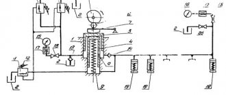
Electrical equipment for press shears ng5223
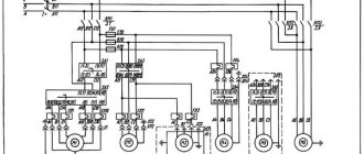
Electrical circuit of press shears ng5223
The electrical circuit (Fig. 16) of the combined shear press is designed to control two sections in the following modes:
- Single strokes (pedal control)
- Adjustment mode (manual rotation).
Operating modes are set by switch SA1 located on the electrical cabinet door. The electrical cabinet (Fig. 17) contains all the ballasts and protective equipment, as well as the TV1 transformer for powering the control circuits (OSM 0.25 380/5-22-110/24). The input circuit breaker QF1 (see Fig. 16) is located in the electrical cabinet on the left side and is locked in the OFF position by switch SA6. The electric motor of the main drive M1, lamps for local lighting of work areas and limit switches are located on the shear press. The layout of electrical equipment is shown in Fig. 18.
The electrical circuit of the machine (see Fig. 16) provides the following types of protection:
- The power circuit is protected from short circuit currents by the input circuit breaker QF1. After automatic shutdown by switch QF1, before turning it on, identify and eliminate the causes of the short circuit;
- the main drive electric motor is protected from overload by thermal relay KK1;
- electromagnets UA1, UA2 and transformer TV1 are protected from short circuit currents from the supply network by fuses FV1, FU4;
- control, alarm and lighting circuits are protected from short circuit currents by fuses FU5, FU6, FU7;
- zero protection, which prevents arbitrary starting of the electric motor when voltage appears after it has disappeared, is carried out by a magnetic starter KM1, connected according to a self-powered circuit.
Installation procedure for press shears НВ5223
When transporting the HB5223 press shears, you must be guided by the sling diagram
Before installing the HB5223 shear press, it is necessary to clean the anti-corrosion coatings applied to the metal
surfaces (except for painted surfaces) and cover with a thin layer of operating lubricant. To do this, degrease the preserved surfaces with white spirit or gasoline, and then wipe with a rag or dry with dry warm air.
Depreservation of spare parts, accessories and replacement units should be carried out in baths with a degreasing solution. Install the shear press on the foundation level. The foundation depth H is determined from the soil conditions, but must be at least 600 mm.
After leveling, pour cement mortar under the feet of the shear press (one part cement to three parts sand) and, when it hardens, evenly tighten the nuts of the foundation bolts, while checking the position of the shear press in level.
Knives for shears for cutting long products. Technical requirements
Knives for press shears are manufactured in accordance with GOST 25454-82 Knives for shears for cutting long products. Technical requirements
Fixed knife-plate for ng5223
Fixed knife-plate for ng5223
- Knives should not have cracks, burrs, shells, sharp corners and edges (except for cutting ones);
- The surfaces forming the cutting edge should not have nicks or burns;
- The cutting edge should not be blunted, chipped, or have nicks;
- Knives must be made of steel grades:
- Х12Ф1, ХБФ according to GOST 5990-73 for cold cutting of steel
- R6M5 according to GOST 19256-73, 4Х5В2ФС according to GOST 5990-73 for hot cutting of steel
- Surfaces forming the cutting edge (front, back) and supporting surfaces - 1.25 microns
Technical characteristics of combined press shears NG5223
| Parameter name | NG5222 | NG5223 | NG5224 |
| Basic parameters of press shears | |||
| Largest dimensions of the processed strip (thickness x width), mm | 16 x 150 | 18 x 190 | 28 x 200 |
| Largest dimensions of the machined wheel (diameter), mm | 45 | 50 | 67 |
| Largest dimensions of 90° corner, mm | 125 x 125 x 12 | 125 x 125 x 14 | 160 x 160 x 20 |
| The largest dimensions of the corner at 45°, mm | 90 x 90 x 9 | 100 x 100 x 10 | 125 x 125 x 14 |
| Largest channel dimensions, profile number | 5..18U | 5..18аУ | 5..30U |
| The largest dimensions of the I-beam, profile number | 10..18 | 10..18 | 10..30 |
| The largest diameter of the hole to be punched, mm | 30 x 16 | 32 x 16 | 40 x 25 |
| The largest dimensions of the grooves to be punched (length x width x thickness), mm | 70 x 65 x 10 | 80 x 65 x 10 | 100 x 85 x 16 |
| The number of knife strokes per minute is not more than | 18 | 17 | 14 |
| Maximum length of sheets to be cut along the back stop, mm | 70..1000 | 70..1000 | 130..1000 |
| Nominal cutting force, kN | 560 | 630 | 1250 |
| Electric motor, kW | 5,5 | 5,5 | 11 |
| Dimensions and weight of press shears | |||
| Dimensions of press shears (length x width x height), mm | 1900 x 1660 x 1950 | 1800 x 1700 x 1865 | 2735 x 1760 x 2445 |
| Weight of press shears, kg | 1940 | 2210 | 7050 |
- Banquetov A.N., Bocharov Yu.A., Dobrinsky N.S. and others. Press-forging equipment, 1970
- Bocharov Yu.A., Prokofiev V, N. Hydraulic drive of forging and pressing machines, 1969
- Belov A.F., Rozanov B.V., Linz V.P. Volumetric stamping on hydraulic presses, 1971
- Zhivov L.I. Forging and stamping equipment, 2006
- Kuzmintsev V.N. Forging with hammers and presses, 1979
- Rozanov B.V. Hydraulic presses, 1959
- Titov Yu.A. Equipment for forging and pressing shops, 2001
- Shcheglov V.F. Forging and pressing machines, 1989
- Berlet Development of forging drawings, 2001
- Rudman L.I. Sheet Forming Equipment Handbook, 1989
- Romanovsky V.P. Handbook of Cold Forging, 1965
- Okhrimenko Ya.M. Technology of forging and stamping production, 1966
- Kuzmintsev V.N. Forging with hammers and presses, 1979
- Meshcherin V.T. Sheet stamping. Atlas of circuits, 1975
Bibliography:
Related Links. Additional Information
- Manufacturers of forging and pressing equipment in Russia
- Classification and designation of hydraulic and crank presses
- Mechanical presses
- Hydraulic presses
- Automatic forging and pressing machines
- Bending and straightening machines
- Guillotine shears, press shears
- Hammers
- Repair of hydraulic systems of metal-cutting machines
- Designations of hydraulic circuits of metal-cutting machines
- Repair of gear hydraulic pumps
Home About the company News Articles Price list Contacts Reference information Interesting video KPO woodworking machines Manufacturers