Information about the manufacturer of the screw-cutting lathe 1K62
Manufacturer of the screw-cutting lathe model 1K62 - Moscow Machine Tools named after. A.I. Efremova , founded in 1857.
Machine tools produced by the Moscow Machine Tool Plant Krasny Proletary, KP
- 1A62
- universal screw-cutting lathe, Ø 400 - 1K62
- universal screw-cutting lathe, Ø 400 - 1K62B
– high-precision universal screw-cutting lathe, Ø 400 - 1K282
- eight-spindle vertical lathe, Ø 250 - 1K620
- universal screw-cutting lathe with variator, Ø 400 - 1K625
- lightweight screw-cutting lathe with an increased line of centers, Ø 500 - 16A20F3
– CNC lathe, Ø 400 - 16B20P
- high-precision screw-cutting lathe, Ø 400 - 16K20
– universal screw-cutting lathe Ø 400 - 16K20VF1
- universal high-precision screw-cutting lathe with digital display, Ø 400 - 16K20M
- mechanized screw-cutting lathe, Ø 400 - 16K20P
- high-precision screw-cutting lathe, Ø 400 - 16K20PF1
- high-precision screw-cutting lathe with digital display, Ø 400 - 16K20F3
- CNC lathe, Ø 400 - 16K20F3S32
- CNC lathe, Ø 400 - 16K20T1
- lathe with operational control, Ø 500 - 16K25
- lightweight screw-cutting lathe with an increased line of centers, Ø 500 - 162
— universal screw-cutting lathe, Ø 420 - 1622
— universal screw-cutting lathe, Ø 120 - 1730
— semi-automatic multi-cutting lathe, Ø 410 - DIP-40 (1D64)
- universal screw-cutting lathe, Ø 800 - DIP-50 (1D65)
- universal screw-cutting lathe, Ø 1000 - DIP-200
– universal screw-cutting lathe, Ø 400 - DIP-300
– universal screw-cutting lathe, Ø 630 - DIP-400
– universal screw-cutting lathe, Ø 800 - DIP-500
– universal screw-cutting lathe, Ø 1000 - MK6046, MK6047, MK6048
- universal screw-cutting lathe, Ø 500 - MK6056, MK6057, MK6058
- universal screw-cutting lathe, Ø 500 - MK-3002
- table lathe, Ø 220
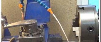
Causes of turning errors on a 1K62 screw-cutting lathe
The following factors can affect the accuracy and purity of processing:
- Incorrect level installation of the machine on the foundation;
- The presence of a gap between the carriage clamping strips and the bed; the presence of a gap between the guides and wedges (it is necessary to tighten the clamping bars and wedges);
- Non-rigid spring mounting of the cutter;
- The part fixed in the chuck has a large overhang (it should be supported by a steady rest or pressed in with the center);
- The chuck faceplate is poorly secured, the chuck mounting screws are not tightened enough;
- Presence of dirt in the conical hole of the spindle;
- The mass of the chuck or workpiece is unbalanced (needs to be balanced);
- Incorrect cutting modes selected (high cutting speed or feed);
- The spindle bearings are not adjusted correctly. (for adjustments, see section “Adjusting the Machine,” page 43).
Repair by grinding
It is not always possible to use planing or longitudinal milling machines for repairs due to the long length of the lathe bed. In this case, the bed guides are restored using a portable device with a grinding head, which is installed directly on the equipment bed.
Repairs can be made on site, without removing the machine from the foundation. This method ensures high repair accuracy, low surface roughness, and is also indispensable when processing hardened surfaces. This method is many times more productive than scraping, but experts still prefer finishing planing.
Adjustment of screw-cutting lathe 1K62
Adjusting the tension of the main drive belts
If over time there is a decrease in spindle torque, then since the machine has a V-belt drive from the main motor to the friction shaft, the belt tension should be checked. If the belts are not tensioned enough, they should be tightened. To do this, remove the lower casing covering the motor unit and loosen the nut securing the wedge pin of the vertical axis clamp of the plate, and the nut securing the sub-motor plate. By turning the round nut counterclockwise, lower the sub-motor plate to the required belt tension.The nuts must be tightened after adjustment.
Adjusting the friction multi-plate clutch
Friction reversible clutch of screw-cutting lathe 1k62
When the belt tension is sufficient, the main drive friction clutch should be adjusted to increase the spindle torque.
To do this, you need to turn off the main drive motor and remove the top headstock cover and the oil distribution tray.
By turning round nut 2 (Fig. 12), you can adjust the direct rotation clutch of the spindle, and by turning nut 3, you can adjust the reverse rotation clutch. To regulate the direct rotation clutch (handle 21 (see Fig. 5) is turned down, and to regulate the reverse rotation clutch it is turned up. In this case, the handle (see Fig. 5) must be tilted to the left (16:1 selection is turned on). Turn nuts can be installed only after latch 4 (see Fig. 12) is recessed into ring 5.
In most cases, it is enough to make 1/12 of a turn (one of the twelve grooves located along the periphery of the nut). You should ensure that the latch slides back into the groove of the nut, otherwise the latter may unscrew spontaneously.
If, after adjustment, turning on handle 21 (see Fig. 5) is difficult, then the clutch is too tight and the nuts should be loosened slightly.
Adjusting the band brake
Band brake of screw-cutting lathe 1k62
If, when the friction clutch is turned off, the spindle does not brake quickly enough, then the brake must be adjusted by tensioning the brake band 1 (Fig. 13) with nuts 2.
The spindle braking time depends on the amount of belt tension. At 2000 rpm, the spindle braking time without the product and chuck should not exceed 1.5 seconds.
When the spindle is in a locked position, lever 3 should be positioned symmetrically to the protrusion of the roller-rack 4, the position of which is secured by ball 5 with a control spring 6.
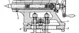
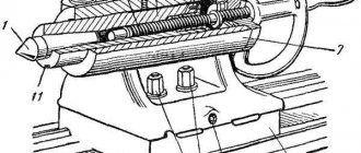
Adjusting the spindle bearings
Supports for the front and rear ends of the lathe spindle 1k62
The spindle bearing supports (front - double-row roller and rear - angular contact bearings) are adjusted at the factory and do not require any adjustment.
During repairs, the bearings are adjusted as follows. The front spindle bearing is adjusted by nut 8 (Fig. 18), located inside the headstock housing, in the following order: release screw 9 and turn the nut in the required direction. By turning this nut, axial movement is carried out (movement of the inner ring of the bearing 10 on the conical neck of the spindle
When the nut is turned to the right, the inner ring of the bearing is tensioned onto the conical journal of the spindle. In this case, the ring is deformed, its outer diameter increases, ensuring a tight fit of all rollers to the surfaces of the inner and outer rings of the bearing, which reduces the radial clearance in the bearing. After adjustment, tighten screw 9 again.
The axial clearance of the angular contact bearings of the rear spindle support is adjusted outside the headstock housing using a nut 11 through a thermal compensator 12. The tension is carried out by turning the nut to the right at an angle of 18..20° before the gaps are selected at the joints between the bearings and spacers. The outer rings are installed close to the stop using nut 13.
Repair by planing
This method is less tedious than scraping and less expensive sanding. For example, the average repair time for machine guides is:
If wear is more than 0.15 mm, manual scraping is replaced by mechanical processing on a longitudinal planing machine with a centralized method of organizing repairs in a repair shop or at a specialized enterprise. The reason is simple: you will have to remove the frame from the foundation and install and align it on the rigid table of the planing machine.
Planing bed guides
At the first stage, test planing is carried out once to obtain a base surface, which will make it possible to determine deviations along the entire length of the bed. To do this, alternately bring the cutter to the most worn surfaces and remove the metal layer until the wear is eliminated. Finish planing is performed in at least two finishing passes with wide carbide cutters. The last pass is performed with a cutting depth of less than 0.05 mm, constantly wetting the cutter and the surface of the guides with kerosene. When wear exceeds 0.4-0.5 mm, the guides are subjected to rough and fine planing. The main disadvantage of this repair method is the considerable time it takes to dismantle the bed, transport, install the bed on the planer table, align and remove the restored bed.
When cutting the flat prismatic surface of the guides, small metal particles of various sizes and shapes are torn out from the solid frame. Furrows and grooves appear on the surface, forming a rough surface. Therefore, sometimes after machining it is impossible to do without scraping or vibration rolling. This increases the strength of the guides due to plastic deformation (changes in the structure of the material). Vibration rolling achieves smoothing of micro-roughness and irregularities by translational movement along and across the axis with specially treated balls or rollers.
Repairing lathe guides using one of the described methods is an element of complex work related to restoring the full functionality and accuracy of metal-cutting equipment. But we should not forget that the quality of the repair, with a minimum period of time for its completion, significantly depends on the degree of preparation of the machine for repair and the qualifications of the mechanic.
Source
Lubrication of screw-cutting lathe 1K62
Lubrication diagram for screw-cutting lathe 1k62
The durability of machine mechanisms largely depends on timely and high-quality lubrication of interacting parts. Before lubrication and startup, the machine is thoroughly wiped.
When the machine is operating, all parts of the mechanism and headstock bearings (Fig. 4) are lubricated by an automatically operating plunger pump 2.
A plunger pump, driven by an eccentric mounted on the friction shaft, supplies oil from a reservoir located at the bottom of the headstock housing, through a plate filter to the front spindle bearing and onto a tray, from where it spreads to the necessary mechanisms of the assembly.
After turning on the machine, a thin stream of oil should appear in the inspection eye located on the top cover of the headstock, indicating normal operation of the pump. If a trickle does not appear, it is necessary to remove the upper headstock cover and, using a stop screw screwed into the drive lever, adjust the normal operation of the pump.
The oil level in the reservoir should be checked daily before starting work. If, when the machine is stopped, the oil level is below the oil indicator mark located on the left side of the headstock, it is necessary to add oil to the reservoir. When the machine is turned on, the oil level in the reservoir decreases, as some of the oil circulates in the system. This does not require additional oil filling.
When changing the oil, remove the oil drain plug located in the oil indicator.
It is recommended to change the oil immediately after turning off the machine, when all wear particles and dust are suspended and removed along with the used oil.
Before filling the housing again with oil, thoroughly rinse and clean the headstock to completely remove any settled dirt. It is unacceptable to use cleaning materials with loose fibers for cleaning.
Fresh oil should be added only after the assembly has been thoroughly dried.
The feed box is lubricated by plunger pump 3 located in the upper part of the housing. The proper operation of the pump can be monitored through the inspection eye located on the front cover of the feed box. To control the oil level, there is an oil indicator located under the sight glass.
Oil is poured into the upper part of the feedbox reservoir. The oil drain plug is located in the bottom wall of the housing.
The plunger pump 4 in the apron is mounted in the bottom cover and is driven by the eccentric of the worm gear shaft. It provides lubrication to all drive parts, bearings and guides of the caliper and carriage.
The oil supply to the caliper and carriage guides is turned on using valve 10.
It is recommended that at the beginning of the shift, set the valve to position “0” (open) and run the carriage along the frame and the lower part of the support along the carriage at high speed two or three times. After this, the tap should be returned to position “3” (closed).
If the valve remains in position “0” (open) while the machine is operating, then all the oil from the apron reservoir will be pumped out during the shift.
Oil is filled through a hole in the left wall of the apron, closed with a plug.
There are two oil drain plugs in the lower apron cover. The transverse and longitudinal feed screw of the caliper and their supports, as well as the axis of the cutting head, are lubricated with grease nipples 7, 11, 12, 13.
Lubrication of the supports of the eccentric shaft of the quill and the tailstock screw is carried out through grease fittings 5, 8, 9, 14; The bearings of the lead screw and the lead shaft are lubricated through a hole closed by plug 6.
During operation of the machine, it is necessary to monitor the operation of the oil pumps and the presence of oil in the tanks. Oil characteristics and lubrication intervals are indicated in the lubrication chart.
Repair by scraping
Scraping of guides or scraping followed by lapping remains the most effective way to restore their geometric and technical accuracy. And now this method is often used, demonstrating excellent results in machine bed repair for many decades. First of all, it is necessary to examine the condition of the guides and determine the degree of their wear. The place where the wear is minimal is taken as the base level, and the measurement data is entered into a table, on the basis of which repairs will be made. In a lathe, the base surface is most often taken to be the location of the tailstock, which practically does not wear out during operation of the equipment. The method includes the following steps:
Since the guides of the lathe bed are quite long, processing is carried out along the beacons, dividing the total length into sections. The first beacon is always the place of maximum production. At a distance less than the length of the straight edge from the first beacon, a second beacon is scraped, located in the same plane as the first. Then the entire surface between the beacons is scraped, followed by moving to the adjacent area. Periodically, apply a ruler with paint to assess the condition of the guides and the quality of work.
Watch the video of rough scraping
Non-hardened parts of lathe guides are subjected to this treatment; the method guarantees the achievement of high surface accuracy (0.002 mm per 1000 mm length). The tiny holes formed after scraping are able to hold the lubricant well and distribute it evenly. The quality of scraping depends entirely on the professionalism of the worker.
Technical data and characteristics of the screw-cutting lathe 1K62
| Parameter name | DIP-200 (1d62m) | 1A62 | 1K62 | 16K20 |
| Main settings | ||||
| Accuracy class according to GOST 8-82 | N | N | N | N |
| The largest diameter of the workpiece processed above the bed, mm | 410 | 400 | 400 | 400 |
| The largest diameter of the workpiece processed above the support, mm | 210 | 210 | 220 | 220 |
| Maximum length of workpiece processed in centers (RMC), mm | 750, 1000, 1500 | 750, 1000, 1500 | 710, 1000, 1400 | 710, 1000, 1400, 2000 |
| Maximum turning length, mm | 650, 900, 1400 | 650, 900, 1400 | 640, 930, 1330 | 645, 935, 1335, 1935 |
| Height of the center axis above the flat guides of the frame, mm | 202 | 215 | 215 | |
| The greatest distance from the axis of the centers to the edge of the tool holder, mm | 228 | 228 | 240 | |
| Height from the supporting surface of the cutter to the axis of the centers (cutter height), mm | 23 | 25 | 25 | 25 |
| The largest cross-section of the cutter holder, mm | 25 x 25 | 25 x 25 | 25 x 25 | 25 x 25 |
| Maximum mass of workpiece processed in the chuck, kg | 500 | 200 | ||
| Maximum mass of workpiece processed in centers, kg | 1500 | 460, 650, 900, 1300 | ||
| Spindle | ||||
| Diameter of through hole in spindle, mm | 38 | 36 | 38/ 47 | 52 |
| The largest diameter of the rod passing through the hole in the spindle, mm | 37 | 34 | 36/ 45 | 50 |
| Number of speed steps for direct spindle rotation | 18 | 21 | 24 | 24 |
| Spindle rotation speed in forward direction, rpm | 11,5..600 | 11,5..1200 | 12,5..2000 | 12,5..1600 |
| Number of spindle reverse rotation frequency steps | 9 | 12 | 12 | 12 |
| Spindle rotation speed in reverse direction, rpm | 18..760 | 18..1520 | 19..2420 | 19..1900 |
| Size of the internal cone in the spindle, M | Morse 5 | Morse 5 | Morse 5/6 | Morse 6 |
| Spindle end flanged | M90x6 | M90x6 | M90x6/ 6 | 6K according to GOST 12593-72 |
| Spindle braking | There is | There is | There is | |
| Spindle material | Art.45 | Art.45 | ||
| Caliper. Submissions | ||||
| Maximum movement of the longitudinal carriage of the caliper by hand, mm | 650, 900, 1400 | 650, 900, 1400 | 640, 930, 1330 | |
| Maximum movement of the longitudinal carriage of the caliper along the roller and along the screw, mm | 650, 900, 1400 | 650, 900, 1400 | 640, 930, 1330 | 645, 935, 1335, 1935 |
| Maximum movement of the transverse carriage of the caliper by hand, mm | 280 | 280 | 250 | 300 |
| Maximum movement of the transverse carriage of the caliper along the roller and along the screw, mm | 280 | 280 | 250 | |
| Longitudinal movement per dial division, mm | No | 1 | 1 | 1 |
| Transverse movement per dial division, mm | 0,05 | 0,05 | 0,05 | 0,05 |
| Transverse movement per one revolution of the dial (transverse caliper screw pitch), mm | 5 | 5 | ||
| Number of longitudinal feed stages | 35 | 35 | 49 | |
| Limits of longitudinal working feeds, mm/rev | 0,082..1,59 | 0,082..1,59 | 0,07..4,16 | 0,05..2,8 |
| Number of cross feed stages | 35 | 35 | 49 | |
| Limits of working cross feeds, mm/rev | 0,027..0,522 | 0,027..0,522 | 0,035..2,08 | 0,025..1,4 |
| Speed of fast movements of the caliper, longitudinal, m/min | No | No | 3,4 | 3,8 |
| Speed of fast movements of the caliper, transverse, m/min | No | No | 1,7 | 1,9 |
| Maximum permissible speed when working on stops, m/min | 0,25 | |||
| Number of metric threads to be cut | 25 | 19 | 44 | |
| Limits of metric thread pitches, mm | 1..12 | 1..12 | 1..192 | 0,5..112 |
| Number of inch threads to be cut | 30 | 20 | 38 | |
| Limits of pitches of inch threads, threads/inch | 24..2 | 24..2 | 24..2 | 56..0,5 |
| Number of modular threads to be cut | 12 | 10 | 20 | |
| Limits of modular thread pitches, module | 0,25..3 | 0,5..3 | 0,5..48 | 0,5..112 |
| Number of cut pitch threads | 24 | 24 | 37 | |
| Limits of pitches of cut pitch threads | 96..7 | 95..7 | 96..1 | 56..0,5 |
| Longitudinal switch stops | There is | There is | There is | There is |
| Transverse switching stops | No | No | No | |
| Overload protection | There is | There is | There is | There is |
| Blocking the simultaneous activation of longitudinal and transverse movement of the caliper | There is | There is | There is | There is |
| Thread indicator | No | |||
| Outer diameter of lead screw, mm | 40 | 40 | ||
| Lead screw pitch, mm | 12 | 12 | ||
| Running shaft diameter, mm | 30 | 30 | ||
| Cutting slide | ||||
| Maximum movement of the cutting slide, mm | 100 | 113 | 140 | 150 |
| Movement of the cutting slide by one division of the dial, mm | 0,05 | 0,05 | 0,05 | 0,05 |
| Movement of the cutting slide per one revolution of the dial (screw pitch of the cutting slide), mm | 5 | 5 | ||
| Maximum angle of rotation of the cutting slide, degrees | ±45° | ±90° | ±90° | ±90° |
| Scale division of the tool slide rotation scale, deg | 1° | 1° | 1° | 1° |
| Number of cutters in the cutting head | 4 | 4 | 4 | 4 |
| Tailstock | ||||
| Tailstock quill diameter, mm | 65 | 70 | ||
| Cone of the hole in the tailstock quill according to GOST 2847-67 | Morse 4 | Morse 4 | Morse 5 | Morse 5 |
| Maximum movement of the quill, mm | 150 | 150 | 150 | 150 |
| Movement of the quill by one division of the dial, mm | No | No | 0,05 | 0,1 |
| The amount of lateral displacement of the headstock body, mm | ±15 | ±15 | ±15 | ±15 |
| Electrical equipment | ||||
| Number of electric motors on the machine | 1 | 2 | 4 | 4 |
| Main drive electric motor, kW | 4,3 | 7 | 10 | 11 |
| Electric motor for fast movements, kW | No | No | 0,8 | 0,75 |
| Electric motor of hydraulic station, kW | No | No | 1,1 | 1,1 |
| Cooling pump electric motor, kW | No | 0,125 | 0,125 | 0,12 |
| Cooling pump (pump) | PA-22 | PA-22 | PA-22 | |
| Dimensions and weight of the machine | ||||
| Machine dimensions (length width height) (RMC = 1000), mm | 2650 x 1315 x 1220 | 2650 x 1580 x 1210 | 2812 x 1166 x 1324 | 2795 x 1190 x 1500 |
| Machine weight (RMC = 1000), kg | 1750 | 2105 | 2140 | 3005 |