The device of the tailstock of a screw-cutting lathe
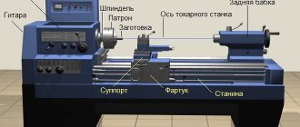
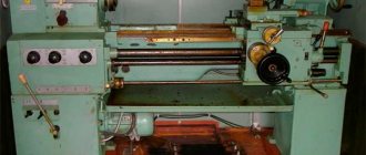
The general view and layout of the tailstock of a screw-cutting lathe is shown in Fig. 33.
Technical characteristics, photographs and drawings are given on the page Screw-cutting lathe 1K62 .
The tailstock serves to support the workpiece during processing in the centers and represents a second support.
When drilling, the tailstock is connected to the caliper carriage with a special clamp and receives mechanical feed from it. The drill is inserted into the quill instead of the center.
The tailstock must satisfy the following conditions:
- under no circumstances move arbitrarily
- give the correct position of the center axis
- enable quick installation along the machine axis
- provide the ability to accurately position the workpiece on both center holes of the machine
- ensure reliable direction of the spindle (quill) of the tailstock and its clamping without disturbing the position of the axis
The stability and reliable position of the tailstock axis are necessary conditions for obtaining satisfactory results when machining on centers and eliminating the possibility of accidents due to the workpiece being pulled out of the centers. This depends on how the tailstock housing is secured to the frame.
The designs of tailstocks are very diverse, but their basic concepts have much in common. Therefore, knowing the basic structure of the tailstock of any medium-sized universal lathe, you can easily understand the design of the tailstocks of other lathes.
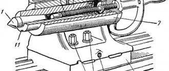
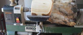
Let's look at the design of the tailstock of a lathe. The tailstock body of this machine, like most other types of machines, consists of two parts: the body itself 1 and the base (raft, bridge) of the tailstock 2.
The raft (bridge) is scraped along the frame guides, and the body is installed on its upper surface.
The planes of contact between the body and the raft are scraped so that the axis of the tailstock coincides in height with the axis of the machine spindle and is parallel to it. Parallelism of the axes is achieved by scraping the vertical edge of the guide bead on the raft. Lateral alignment of the axes is achieved by moving the body along the raft using a square-head screw and nut. The body is attached to the raft and at the same time to the frame using two bolts 4 and a lining 3.
Achieving coincidence of the axes of the spindles of the headstock and tailstock by scraping the supporting planes of the headstock body requires a significant investment of time. Therefore, as a rule, during a major overhaul, the coincidence of the axes of the headstock and tailstock is achieved by boring the hole for the tailstock spindle. In this case, it becomes necessary to replace the tailstock spindle, which is finally machined along the outer diameter only after boring the tailstock body.
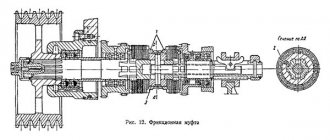
The tailstock spindle (quill) 7 is a hollow cylinder, the front edge of which is made in the form of a Morse cone into which a center 6 or drill is inserted, and a nut 9 is inserted into the rear edge. Using this nut and a screw 8 with a flywheel 10, the spindle can move along the axis . Key 5 protects the spindle from turning. The spindle is clamped with a handle, which has right and left threads at the end for clamping nuts. When the spindle is retracted completely into the tailstock, screw 8 with its end rests against the end of center 6 and pushes it out of the spindle body. Thus, in this design, knocking the center out of the cone is very convenient.
In heavy machines, the spindle does not have a nut, the cutting is done directly on the spindle, and the flywheel bushing is a nut. It is impossible to knock out the center from the end of such a spindle. Therefore, ordinary centers are not suitable for such spindles; the centers should be threaded. A nut is screwed onto the thread, with which the center can be pressed out, or flats are made on the centers, which make it possible to turn the center with a key and thereby release it from the socket. The use of simple centers on these machines should be prohibited, since they are pressed in and can only be knocked out by hitting a sledgehammer or heating the spindle with blowtorches. This leads to damage to the spindle cone.
When processing flat cones, it is necessary to shift the center of the tailstock in the transverse direction. For this purpose, the tailstock body and the base are connected to each other by a transverse key. The transverse displacement of the headstock body relative to the base is made by screws and a nut.
Tailstock of lathe 1k62. Assembly drawing
Tailstock of lathe 16k20. Assembly drawing
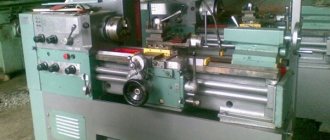
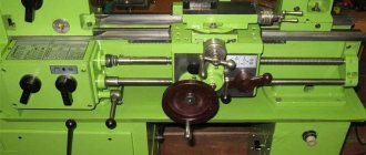
Guides of the bed and supports of a 16K20 CNC screw-cutting lathe.
In the Technologist's Tips section, we have already described the repair of the caliper guides and crossbars of the same machine. In a new case, at another enterprise, the guides and frames and supports were restored. Final video:
Let’s describe everything in more detail, since in this case two important parameters of the guides’ operation are very indicative - excellent gliding and the absence of a “stick-slip effect” after restoration. For more information about this in theory, see here https://remval.by/category-products/moglice-pretsizionnye-iznosostojkie-pokrytiya-skolzheniya/
The wear of the bed guides reached 1.5 mm in places.
screw-cutting lathe 16K20 with CNC
Our company offered to carry out repairs WITHOUT DISASSEMBLY AND DISASSEMBLY OF THE MACHINE at its location in the Customer’s workshop. Such repairs on site are carried out using wear-resistant material “Moglice” using the imprint method. In this case, the guides are restored to factory accuracy standards. Moglais allows you to make any print with an accuracy of 1 micron.
The process consists of two stages: 1 – repair of the friction surfaces of the frame using special equipment (ruler-conductor) 2 – formation of the friction surfaces of the caliper using the imprint method from the restored frame
Repair of bed guides
Using a calibration tool (SD ruler), we identified areas of wear that were subject to repair. Sections of worn metal were cut out from the frame in a layer of 2.5 - 3.0 mm. Next, we made equipment, which then formed new sliding surfaces. In this repair, a ground channel was used, the working edges of which were also checked for accuracy. Moglice P 1130 was applied in excess to the prepared cut areas on the bed.
Then a polished conductor channel, treated with separating material 1354 Trennmittel Fl, was lowered and secured onto the moglies. After approximately 16 hours, the jig was removed from the surface being repaired. We received completely new ideal wear-resistant sliding surfaces that fully comply with the required accuracy standards.
Repair of caliper guides
Before our intervention, caprolon-type plastic was used on the caliper guides, which quickly warped and came off. After removing it, the caliper was adjusted to the required clearance relative to the frame using adjusting bolts and manufactured end bosses. Next, according to DiamantMetallplastic rules, Moglice P 1130 material was applied in excess
The support was turned into its working position and lowered onto the restored frame using a crane beam, treated with release agent 1354 Trennmittel Fl
After approximately 16 hours, the caliper was moved from its place along the guides by applying an impact load, turned over and cleaned of the squeezed out excess and hardened material.
Lubrication channels were cut on the resulting surfaces.
Installed on the bed. The result of the work in the video. The presented video clearly shows the quality of fit of the new sliding surfaces and the low coefficient of sliding friction of the moglies-moglies material pair. Submit your application
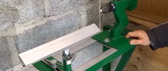
Repair and restoration of the tailstock of a lathe
When repairing the tailstock, the accuracy of the mating surfaces of the bridge with the frame and the body, the accuracy of the body opening and the height of the centers of the front and rear stock are restored, the quill, feed screw and other parts are repaired or remanufactured.
The most labor-intensive operations are to restore the accuracy of the hole in the body for the quill and restore the height of the centers.
The hole for the quill in the body is repaired by lapping, boring, followed by finishing, and using acrylic plastics.
Laps usually repair lightly worn holes. In this case, the height of the centers is restored by placing compensation pads on the guides and a new quill is made.
When repairing by boring, the height of the centers is simultaneously restored. After boring, the hole is usually finished with laps, and the quill is made of a larger diameter.
Acrylic plastics restore both the precision of the quill fit and the height of the centers. In this case, the quill is not manufactured, but repaired.
This repair method is the most effective, since it requires 3-5 times less time and money than the first two methods.
The two options for repairing the tailstock discussed below clearly confirm the profitability of repairs using acrylic plastics, in particular styracrylic of the TSh brand.
Repair of the tailstock housing and bridge without the use of acrylic plastic
The repair sequence is as follows:
- The surface of the 9th body is scraped (Fig. 60). The number of paint prints must be at least 10 on an area of 25 X 25 mm
- The surface 10 of the bridge 8 is milled and the cover is installed with glue or screws. If the bridge protrusion is tightly coupled with the housing groove, this operation is not performed
- The surfaces of the bridge mating with the hull are scraped (along the hull). The number of spots when checking for paint is at least 10 on an area of 25 X 25 mm. The protrusion of the bridge must fit tightly into the groove of the housing (without play)
- The surfaces of the bridge are scraped along the frame guides. The number of paint prints is 10-15 on an area of 25 X 25 mm. At the same time, when scraping, the surface mating with the body is ensured to be horizontal with an accuracy of 0.05 mm per 1000 mm of length. The check is carried out using a level installed on surface 9 along and across the frame guides. The frame is installed and leveled, while the plane for attaching the feed box must be positioned strictly vertically.
- Attach the bridge to the hull
- The bead rod is secured in the spindle of the machine headstock. The axis of the bead rod at the point where the cutter is attached must be 0.05 mm higher than the normal position of the spindle axis, for which: the measuring rod of the indicator, mounted on the machine support, is brought to the upper generatrix of the bead rod (at the point where the cutter is attached) and this position is fixed; loosen the front bolts securing the headstock (the spindle axis is already aligned parallel to the frame guides), use a lever to slightly raise the front part, place 0.02-0.05 mm thick foil under the front ends of the guides and secure the headstock to the bed; bring the indicator to the upper generatrix of the bead rod and notice its new position, in which the axis of the bead rod should be located 0.05 mm above the spindle axis.
- Install the tailstock in front of the caliper carriage and apply a weight for rigidity
- Boring the hole for the quill in the tailstock body (in 2-3 passes), spindle rotation speed 250 rpm; feed 0.1 mm/min. In this case, the surface finish must be no lower than V5, taper - no more than 0.02 mm, ovality - no more than 0.01 mm.
- Grind the hole in the body using an expanding mandrel mounted in the spindle and sandpaper. Spindle rotation speed 500-800 rpm, feed 10-15 m/min. Surface finish V7, taper - no more than 0.02 mm, ovality - no more than 0.01 mm
- The hole in the body is fine-tuned using a cast iron lap. Spindle rotation speed 200-300 rpm, feed - 5-8 m/min. In this case, a surface cleanliness of V 8 is achieved, the taper should be no more than 0.01 mm, and the ovality should be no more than 0.005 mm.
- Remove the foil from under the headstock guides and secure the headstock to the bed. The tailstock is assembled with a newly manufactured and fitted quill. The movement of the quill should be smooth, without backlash. The clamp should ensure reliable fastening of the quill.
- Check the position of the quill in relation to the bed guides and the coincidence of the centers of the front and rear stock, in accordance with the technical specifications in accordance with GOST 42-56.
The considered tailstock technological process is widely used in many factories, despite its significant labor intensity.
Restoring the tailstock with acrylic plastic
Restoring the tailstock with acrylic plastic is very simple and effective, since operations on precise boring and finishing of the housing hole are eliminated and it is possible to preserve the old quill. Bridge repairs are carried out in the same way as for repairs without acrylic plastic.
The technological process of restoring the hole in the tailstock housing includes the following operations:
- The hole for the quill in the body 4 of the tailstock (Fig. 60) is bored on a boring or lathe, and a layer of metal equal to 2-3 mm is removed. The cleanliness of the processing must correspond to V 1, taper and ovality are allowed no more than 0.5 mm.
- In the spindle 2 of the headstock 1 of the machine, the axis of which is adjusted to be parallel to the bed guides, a hollow mandrel with a plug 7 is installed. The outer diameter of the cylindrical part of the mandrel corresponds to the outer diameter of the repaired quill and has a size 0.01 mm larger than the quill. The mandrel is installed eccentrically relative to the spindle axis by 0.07-0.08 mm. To do this, a gasket shaped like a truncated cone with a thickness of 0.07–0.08 mm is placed in the conical hole of the spindle before installing the mandrel. The material for the gasket is paper or foil. The shape of the gasket (truncated cone) ensures uniform runout at both ends of the mandrel.
- By rotating spindle 2, check the runout of the mandrel, which should be no more than 0.15-0.18 mm, and install the spindle so that the generatrix of the mandrel with the largest positive deviation is located above the spindle axis. This arrangement of the mandrel ensures that the difference in height between the centers of the headstock and tailstock (0.05-0.07 mm) is established in accordance with the requirements of the technical specifications.
- In the body of the tailstock 4, three holes with a diameter of 6-8 mm are drilled above the hole for the quill; holes are located in the middle and along the edges of the body
- Degrease the bore of the housing and dry for 15-20 minutes until the solvent has completely evaporated.
- A thin, even layer of soap is applied to the mandrel, the tailstock body is installed and bolted to the frame.
- The hole for the quill (the space between the mandrel and the headstock body) is sealed with rings and plasticine 6; The holes of the quill fastening devices are also sealed, and three funnels 3 and 5 are installed from plasticine above the three drilled holes.
- Prepare an acrylic solution and pour it into the middle funnel. Filling is completed when the mass of styracrylic partially fills the outer funnels
- The flooded tailstock is kept in place for at least 2 hours at a temperature of 18-20 ° C
- They move the tailstock, protect the body from plasticine and tides of plastic, make lubrication grooves, drill holes, chisel the keyway and assemble the tailstock
Tailstock quill repair
This process involves grinding the outside diameter and restoring the taper bore by installing an expansion sleeve.
The compensation sleeve (Fig. 61, a) has a cylindrical shape on the outside and a cone on the inside. The bushing is often made from case-hardened steel, with the cone hardened to HRC 58-60. The wall thickness of the bushing near the largest diameter of the cone is taken to be 2 mm or more (depending on the diameter of the quill).
The outer diameter of the bushing is made according to the bored hole of the quill with a gap of 0.05 mm, the cleanliness of the machined surface is V5-V6.
The bushing is glued into the quill and after hardening (after 24 hours), the conical hole is ground.
As an example, we give the technology for restoring the tailstock quill of a screw-cutting lathe model 1E61, which consists of two stages:
- manufacturing an expansion sleeve (Fig. 61, a)
- quill repair (Fig. 61, b)
- The sleeve is machined with technological allowances, Morse taper No. 3, for grinding the interference is 7-8 mm, not counting the allowance of 5 mm. Cement to a depth of 0.8-1.2 mm. Remove technological allowances, leaving 1 mm per side. Kalat, HRC 58-62. The outer diameter and ends are machined according to the drawing (checked on a cone mandrel).
- Bore a hole in the quill Ø30A to a length of 90 mm (check for runout with an accuracy of 0.05 mm, finish V 5). Install the bushing with epoxy glue and keep it for 24 hours at a temperature of 18-20° C. Insert plugs on both sides, center them with an accuracy of 0.02 mm, grind the quill along the top to size and trim the front end, chamfering. Grind the outer diameter to size. The lubrication groove is milled according to the sketch. The numbers are engraved according to the sketch. Remove the plugs. Then the quill is aligned with an accuracy of 0.01 mm, the Morse taper No. 3 is ground on the cork and the front end is clean.
A quill repaired using this technology has increased wear resistance of the tapered hole, and the cost of repair is significantly lower than the cost of manufacturing a new quill.