In fact, the design of a lathe, regardless of its model and level of functionality, includes standard structural elements that determine the technical capabilities of such equipment. The design of any machine belonging to the category of turning group equipment consists of such basic elements as a headstock and tailstock, a support, a device apron, a gearbox for changing speeds, a feedbox, an equipment spindle and a drive motor.
Main parts of a metal lathe
Headstock
Tailstock
Caliper
Drive shafts
Gear shift lever
Limbo
How the bed and headstock of the machine are arranged
The frame is a supporting element on which all other structural elements of the unit are installed and fixed. Structurally, the frame consists of two walls connected to each other by transverse elements that give it the required level of rigidity. Individual parts of the machine must move along the bed; for this purpose, it is equipped with special guides, three of which have a prismatic section, and one has a flat section. The tailstock of the machine is located on the right side of the bed, along which it moves thanks to internal guides.
The cast lathe bed is reinforced with stiffening ribs and has ground and hardened guides
The headstock simultaneously performs two functions: it gives the workpiece rotation and supports it during processing. On the front part of this part of the lathe (it is also called the “spindle head”) there are gearbox control handles. With the help of such handles, the machine spindle is given the required rotation speed.
In order to simplify the control of the gearbox, next to the shift knob there is a plate with a diagram that indicates how to position the handle so that the spindle rotates at the required frequency.
Speed selection lever for BF20 Yario machine
In addition to the gearbox, the headstock of the machine also contains a spindle rotation unit, in which rolling or sliding bearings can be used. The device chuck (cam or drive type) is fixed at the end of the spindle using a threaded connection. It is this unit of the lathe that is responsible for transmitting rotation to the workpiece during its processing.
The frame guides along which the machine carriage moves (the lower part of the support) have a prismatic cross-section. They are subject to high demands on parallelism and straightness. If these requirements are neglected, it will be impossible to ensure high quality processing.
Main parts and components of a screw-cutting lathe
3Despite the variety of types, designs and sizes of lathes, they have common components, and details that we will consider using the example of a modern screw-cutting lathe shown in Fig.
The main components of a screw-cutting lathe are the bed, the front
headstock, tailstock, feed box, apron and caliper.
The bed is used for mounting the main components of the machine on it, and the support and tailstock can move along the bed in the direction.
The headstock serves to secure the workpiece and transfer it
rotation. The gearbox and spindle are mounted in the headstock.
The tailstock serves to support the other end of the workpiece; also used for installing drills, countersinks, reamers and other tools.
The feed box of the machine is designed to transmit rotation to the lead screw or lead shaft, as well as to change the number of their revolutions.
The apron serves to convert the rotational movement of the lead shaft and lead screw into the rectilinear movement of the caliper.
The support is designed to move the cutter fixed in the tool holder in the longitudinal, transverse and oblique directions.
Shown in Fig. The machine has a running shaft and a lead screw and is called a screw-cutting lathe. It got its name because, in addition to all the usual turning operations, it can be used to cut threads with a cutter.
A machine without a lead screw is simply called a lathe. On a lathe, you can perform various turning operations, in addition to cutting threads with a cutter.
BED
The frame is made of cast iron and consists of two longitudinal walls connected by transverse ribs for greater rigidity. The headstock is secured at one end of the frame, and the tailstock is installed at the other. The tailstock can be moved along guides along the bed and secured in the required position. The lower plate of the support, called the carriage, also moves along the frame guides. The outer guides of the frame, along which the carriage moves, usually have a prismatic shape. One of the internal guides along which the tailstock is moved has a flat surface. The bed guides must be accurately machined and strictly straight and parallel, since the accuracy of the processing of parts depends on this.
HEADSTOCK
The purpose of the headstock is to secure the workpiece and transmit rotational motion to it.
The most important part of the headstock is the spindle. The spindle is the main shaft of the gearbox. The spindle transmits the rotation of the workpiece using a cam or drive chuck screwed onto the right threaded end of the spindle. To set the spindle into rotation, as well as to change the number of its revolutions per minute, there is a special mechanism in the headstock housing.
In modern lathes, such a mechanism is the gearbox. It is located inside the cast iron body of the headstock and consists of a number
gears, shafts and other parts.
Rotation is transmitted from the electric motor to the drive pulley using a belt. The pulley sits freely on the gearbox shaft. Inside the pulley there is an engagement clutch. If you turn on the clutch using the starting handle, the pulley will connect to the gearbox shaft and cause it to rotate.
A block of gear wheels sits on the shaft, which can be moved along a key along the shaft using a handle. In the right position of the block, the wheel engages the wheel; in the middle position - wheel with wheel and in the left position - wheel with wheel. The wheels sitting on the shaft are rigidly connected to this shaft. Note that the numbers of teeth of the meshing gears are different in all three cases. Therefore, although the shaft has a constant number of revolutions, the shaft can be given three different revolutions per minute depending on which pair of gears is in mesh.
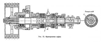
The wheels are cordoned off accordingly with the wheels freely sitting on the spindle. In order for the spindle to rotate, you need to engage the double-sided gear coupling located on it with one of the gears, for which their ends are equipped with teeth (cams). The clutch, moved by the handle along the spindle key, is always connected to the spindle. Therefore, connecting the clutch to either of the two wheels causes the connection of that wheel to the spindle.
Let's assume that the clutch is turned to the right. This means that rotation is transmitted to the spindle through gears. In this case, in accordance with the three positions of the handle, the spindle receives three different speeds. If the clutch is engaged to the left, then transmission occurs through other wheels. In accordance with the same three positions of the handle, the spindle receives three other numbers of revolutions. Thus, the spindle receives a total of six different speeds by switching handles located on the outer wall of the headstock.
How to turn the handles to obtain the required number of spindle revolutions is indicated on a metal plate attached to the wall of the headstock.
TAILSTOCK
The tailstock housing is located on a plate that moves along the frame guides. A quill with a nut fixed in it can move longitudinally in the housing hole. At the front end, the quill is equipped with a conical hole into which the center, and sometimes the tail part of the drill or reamer, is inserted. The quill is moved by means of a handwheel that rotates the screw; When the screw rotates, it moves the nut, and with it the quill.
To prevent the quill from turning when the handwheel rotates, it has (at the bottom) a keyway into which a key embedded in the tailstock housing fits. The handle serves to secure the quill in the headstock body. The axes of the machine spindle and the tailstock quill must coincide; a screw is used to install the quill along the spindle axis. (Using a screw, you can move the body relative to the plate in the transverse direction, which is sometimes resorted to when turning flat cones.
To turn parts of different lengths in the centers, move the plate along with the tailstock body along the bed and secure it in the desired position with clamping bolts or using an eccentric clamp and bracket. Use the handle to turn the eccentric roller and release or tighten the bracket. Having released the bracket, move the tailstock and, having installed it in the desired position, tighten the bracket again.
To remove the rear center from the tapered hole of the quill, rotate
handwheel so as to retract the quill into the tailstock housing until
refusal. In the extreme position, the end of the screw pushes out the center.
FEED MECHANISM
The feed motion is communicated to the cutting tool in order to spread
gradually the process of cutting onto the entire surface of the workpiece.
Longitudinal feed is directed along the axis of the machine spindle; transverse - perpendicular to this axis. The feed rate is the length of movement of the cutter per revolution of the spindle; it is measured in millimeters.
The caliper receives its mechanical feed movement from a lead screw or lead shaft. They, in turn, are driven by the machine spindle through a series of gears.
At the end of the spindle is attached a gear, to which either a gear or a gear can be engaged by means of a lever. The gear is constantly in mesh with and against the wheel. If, by turning the lever down, a wheel is engaged with a gear, the rotation of the wheel will be transmitted through two intermediate wheels. By turning the lever up, the wheels are engaged directly with the wheel. In this case, wheel 4 will receive rotation only through one intermediate gear, therefore, it will rotate in a different direction than in the first case.
The mechanism under consideration is called a snaffle. It is widely used in older types of lathes and is designed to change the direction of feed. If the lever is fixed in the middle position, the gears will not engage with the wheel and the feed mechanism will be turned off.
The snaffle is usually placed inside the headstock housing. The end of the shaft on which the gear sits protrudes outward. Another wheel can be mounted on it, from which the rotation is transmitted from the wheels to other wheels. The wheel receives rotation from the chassis, screw or drive shaft. These four gears are replaceable, meaning they can be removed from the machine and replaced with others with different numbers of teeth.
By selecting the number of teeth of these wheels accordingly, you can obtain the required rotation speed of the lead shaft or lead screw. In order for the installed gears to mesh with each other, first move the wheel axle along the straight groove of the guitar until the wheel engages the wheel. Then they secure this axle in the groove with a bolt and, turning the slope, engage the wheels. Finally, secure the guitar with a bolt. When installing replacement wheels, you need to leave as small a gap between their teeth as possible, but clearly noticeable when rocking. A tight connection may cause teeth to break.
In machines that do not have a feed box, the gear is usually located on the lead screw, which communicates the feed to the support. In more advanced machines, this wheel is installed on the first roller of the feed box.
The feed box is used to change the rotation speed of the lead screw and the lead shaft, i.e., to change the feed amount. If the machine does not have a feed box, then the feed rate can be changed only by changing the gears on the guitar. This is very inconvenient, as it takes a lot of time, but this method is also used in modern lathes when cutting precise threads, in addition to the feed box.
The first feed roller receives rotation from the guitar's replaceable gears. This shaft has a long keyway into which the key of a gear located in the lever slides. The lever carries an axis on which a gear wheel, constantly engaged with the wheel, rotates freely (By means of the lever, the wheel together with the wheel can be moved along the shaft; by turning the lever, the wheel can be engaged with any of the ten gear wheels mounted on the shaft. The lever can occupy ten different positions according to the number of gears. In each of these positions the lever is held by a pin inserted into one of the holes in the front wall
feed boxes
At each position of lever 4, due to the adhesion of wheel 6 with any wheel from the set, the roller receives a different rotation speed. At the right end of this roller, on a key, there is a movable gear wheel with a row of projections on the right end. In the left position, the wheel is engaged with a wheel mounted on the drive shaft. If the wheel is moved to the right along the shaft, it will disengage with the wheel and the end protrusions will engage with the jaw clutch, which is rigidly seated on the lead screw. In this case, the roller will be directly connected to the lead screw. When the lead screw is turned on, the lead shaft remains stationary; on the contrary, when the drive shaft is turned on, the lead screw remains motionless.
On the wall of the feed box there is usually a sign indicating what feed or thread pitch is obtained for each of the ten lever positions with a certain selection of guitar replacement gears
CALIPER
The lower plate of the support, called the carriage, or longitudinal slide, can move along the bed guides mechanically or manually and gives the cutter movement in the longitudinal direction. The top surface of the carriage has dovetail-shaped guides located perpendicular to the bed guides. Cross slides can move along the carriage guides mechanically or manually, through which the cutter receives movement perpendicular to the spindle axis.
The rotating part of the caliper is located on the upper surface of the cross slide. After unscrewing the nuts, you can rotate this part of the caliper at the desired angle relative to the frame guides and then tighten the nuts again. On the upper surface of the turning part there are dovetail-shaped guides along which the upper caliper slide can move when the handle is rotated.
Tool holders. A tool holder or cutting head is installed on the upper slide of the caliper, in which the cutter can be secured with screws.
Tool holders come in various designs. On light machines, a single tool holder is used. It is a cylindrical body into the slot of which a cutter is inserted and secured with a bolt. The cutter rests on a lining, the lower spherical surface of which is in contact with the same surface of the ring. This device allows you to tilt the lining with the cutter and set its cutting edge to the height of the centers. The lower part of the tool holder, which is T-shaped, is inserted into the groove in the upper part of the support. Fastening the cutter in a tool holder of this type is quick, but not strong enough; Therefore, it is used mainly for small jobs. The cutter is secured more firmly in the tool holder. The tool holder, equipped with a T-shaped block, is secured to the upper part of the caliper with a nut. To adjust the position of the cutting edge of the cutter in height, the tool holder has a pad, the lower spherical surface of which rests on the same surface of the tool holder block. Secure the cutter with two bolts. This type of tool holder is used on both small and large machines.
On medium-sized lathes, a tetrahedral rotating cutting head is predominantly used, which makes it possible to secure four cutters at once, which can be used alternately. To do this, you need to rotate the cutting head and place the required cutter in the working position. Before turning the cutting head, it is necessary to unfasten it by turning the handle connected to the nut sitting on the screw. After each rotation, the cutting head must be clamped again using the same handle.
On large lathes, single tool holders are used. In this case, the cutter is installed on the plane of the upper part of the caliper and secured with a bar, tightening the nut. To protect the screw from bending, the bar is supported by a screw resting on the shoe. When the nut is unscrewed, the spring lifts the bar.
APRON
An apron is attached to the bottom surface of the carriage, which contains mechanisms for converting the rotational movement of the lead shaft and lead screw into the linear movement of the caliper.
The transverse feed of the cutter is carried out by moving the transverse slide of the support
ta. To do this, the handle rotates the screw, the nut of which is fastened to the transverse slide. The handwheel is used to communicate longitudinal feed (manually) to the support along the bed guides. For more precise mechanical longitudinal movement of the caliper, a lead screw is used, to which is connected a uterine nut installed in the caliper apron. When cutting a thread, both halves of the nut are brought together using a handle; they grab the thread of the screw, during the rotation of which the apron, and with it the caliper, receive longitudinal movement.
The mechanism for sliding and spreading the halves of the split nut is designed as follows. A disk with two spiral slots is attached to the handle shaft, into which the pins of the lower and upper halves of the nut fit. When the disk is turned, the slots force the fingers, and therefore the halves of the nut, to move closer or further apart. Both halves of the nut slide along the dovetail-shaped apron guides. The lead screw and the nut are used only when cutting threads.
In all turning operations, except for cutting threads with a cutter, longitudinal feed is carried out using a gear rack rigidly attached to the frame and a gear wheel installed in the apron rolling along it. The rack wheel can be rotated either manually or from the drive shaft. The long keyway of the shaft receives the key of the worm sitting on it. As the worm rotates, it sets the worm wheel in motion. To turn on the mechanical longitudinal feed, you need to connect the worm wheel to the wheel with a handle (using a clutch). The latter will impart rotation to the wheel coupled to it, and the rack and pinion wheel sitting on the same roller will rotate with it. This wheel rolls along a stationary rack, driving the apron and caliper along the bed.
Next to the worm on the drive shaft sits a bevel gear, the key of which also slides in the long keyway of the drive shaft. Rotating together with the shaft, the wheel causes another conical wheel and cylindrical wheels to rotate. Using the button you can connect the wheel to the wheel. Together with the wheels, the screw rotates, carrying out the transverse feed of the cutter. To turn off the cross feed, the wheel is disengaged from the wheel using the same button.
Manual transverse feed is done with a handle, and manual longitudinal feed is done with a handle through the wheels and rack.
If you turn on the longitudinal feed mechanism from the drive shaft at the same time as closing the nut on the lead screw, the apron mechanism or feed box will break. To prevent the possibility of such incorrect activation, the machine has a special mechanism called a locking mechanism. It eliminates the possibility of turning the handle and closing the nut when the feed from the running shaft is turned on, or turning the handle for turning on the mechanical longitudinal feed from
shaft if the uterine nut on the lead screw is closed.
3
Purpose of the tailstock of turning equipment
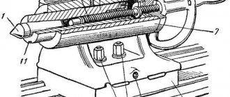
The tailstock of a lathe, the design of which can include several design options, is necessary not only for fixing parts of considerable length, but also for fastening various tools: drills, taps, reamers, etc. An additional center of the machine, which is installed on the tailstock, can be rotating or stationary.
Tailstock structure: 1, 7 – handles; 2 – handwheel; 3 – eccentric; 4, 6, 9 – screws; 5 – traction; 8 – quill; A – counterbore
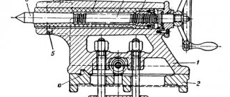
A scheme with a rotating rear center is used if the equipment is used for high-speed processing of parts, as well as when removing chips that have a large cross-section. When implementing this scheme, the tailstock is made with the following design: two bearings are installed in the quill hole - a front thrust bearing (with tapered rollers) and a rear radial one - as well as a bushing, the inner part of which is bored to a cone.
Axial loads arising during processing of a part are absorbed by a thrust ball bearing. Installation and fixation of the rear center of the equipment is ensured by the tapered hole of the bushing. If it is necessary to install a drill or other axial tool in such a center, the sleeve can be rigidly fixed with a stopper, which will prevent it from rotating with the tool.
Rotating center KM-2 of a table lathe Turner-250
The tailstock, the center of which does not rotate, is fixed to a plate that moves along the guides of the machine. The quill installed in such a headstock moves along the hole in it using a special nut. In the front part of the quill itself, into which the center of the machine or the shank of the axial tool is installed, a conical hole is made. The movement of the nut and, accordingly, the quill is ensured by the rotation of a special flywheel connected to the screw. What is important is that the quill can also move in the transverse direction; without such movement it is impossible to process parts with a flat cone.
Machine device
If we look at the drawing of a home turning device, then it is obvious that its headstock consists of the following elements:
- V-belt;
- two-stage pulley;
- spindle;
- ball bearing.
The tailstock in a lathe contains the following parts:
- frame;
- center;
- two handles;
- quill;
- three screws;
- flywheel;
- craving;
- lever arm;
- screw.
It must be borne in mind that the driven center is located on the tailstock and can be either dynamic or stationary. Such a center can be made from a simple bolt, sharpened at one end, giving it a cone shape. They are treated with technical oil (solid oil) and inserted inside. The tailstock of a wood lathe is made in a similar way, using the same cone-shaped bolt with a lock nut.
Tailstock detailing
Spindle as an element of a lathe
The most important structural component of a lathe is its spindle, which is a hollow metal shaft with a conical inner hole. What is noteworthy is that several structural elements of the machine are responsible for the correct functioning of this unit. It is in the inner conical hole of the spindle that various tools, mandrels and other devices are fixed.
Spindle drawing of screw-cutting lathe 16K20
In order to be able to install a faceplate or a lathe chuck on the spindle, its design includes a thread, and to center the latter there is also a collar on the neck. In addition, to prevent spontaneous unscrewing of the chuck when the spindle is quickly stopped, some models of lathes are equipped with a special groove.
The results of machining parts made of metal and other materials on the machine largely depend on the quality of manufacturing and assembly of all elements of the spindle assembly. In the elements of this unit, in which both the workpiece and the tool can be fixed, there should not be even the slightest play that causes vibration during the rotational movement. This must be carefully monitored both during the operation of the unit and when purchasing it.
In spindle units, which can be immediately determined from their drawing, sliding or rolling bearings can be installed - with roller or ball elements. Of course, rolling bearings provide greater rigidity and accuracy; they are installed on devices that process workpieces at high speeds and with significant loads.
Caliper structure
A lathe support is a unit that ensures the fixation of the cutting tool, as well as its movement in the inclined, longitudinal and transverse directions. It is on the support that the tool holder is located, moving with it due to a manual or mechanical drive.
Support with carriage for machine Optimum D140x250
The movement of this unit is ensured by its structure, which is characteristic of all lathes.
- The longitudinal movement, for which the lead screw is responsible, is performed by the caliper carriage, while it moves along the longitudinal guides of the frame.
- Transverse movement is performed by the upper - rotating - part of the support, on which the tool holder is installed (such movement, due to which the depth of processing can be adjusted, is carried out along the transverse guides of the support itself, which are shaped like a dovetail).
Quick-change tool holder MULTIFIX cartridge type
The tool holder, also called the cutting head, is installed on the top of the support. The latter can be fixed at different angles using special nuts. Depending on the need, single or multiple tool holders can be installed on lathes. The body of a typical cutting head has a cylindrical shape, and the tool is inserted into a special side slot in it and secured with bolts. There is a protrusion on the bottom of the cutting head that fits into a corresponding slot on the support. This is the most typical tool holder mounting scheme, used primarily on machines designed to perform simple turning work.