What is known about the production of the machine
The 6P82 horizontal milling machine was developed in the 70s of the last century. After testing and modifications, it was put into mass production at the Gorky Milling Machine Plant in 1970. The model was modernized several times and CNC was installed on it.
Currently, the plant on the Volga continues to produce modern models of milling metalworking equipment based on 6P82. Old-style machines have migrated to home workshops and small businesses and continue to produce planks, tables and slats with high precision.
Reference! The Gorky milling machine plant was put into operation in 1931 under the Stalinist program of industrialization of the country. Until the end of the 20th century, it was practically the only manufacturer of milling machines of various types in the country. Now the plant's equipment is produced under the FZS brand.
General form
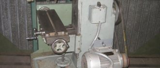
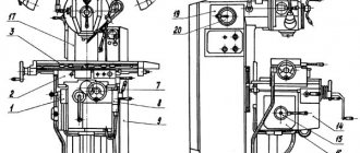
The 6P82 milling machine is made in a single-column version. Its cast frame is located vertically and rests on the foundation slab. The hollow structure houses the gearbox on one side and the electrical control cabinet on the other. The engine is located behind. It attaches directly to the back wall. The drive shaft inside the frame is connected to the spindle assembly and gearbox.
In the front part, the console moves along the vertical guides of the frame, resting on the lead screw. The horizontal table protrudes on the sides beyond the remaining nodes. The spindle is stationary. To install the mandrel under the disk cutters, a trunk with earrings is moved from above.
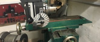
Connecting bases for milling machine 6M82. Trunk, earrings and spindle.
The connecting base consists of: trunk, earrings and spindle.
Trunk
The trunk serves to support the free end of the milling mandrel. For this purpose it is equipped with special pendants. The other end of the mandrel is attached to the spindle cone using a bolt. The trunk is attached to the guide profiles and can move along them thanks to a gear rack.
The trunk is attached to the frame at the front and back with two clamps. Both clamps must be fully tightened. The front protrusion of the trunk is usually equipped with two earrings, tightened with a nut (less often - one).
Earring
Each earring has a bearing in the form of a bronze bushing. This bushing helps control the clearance in the plain bearing.
It is very important to monitor the oil level in the inner recess of the earring. Sometimes, in order to give the trunk additional rigidity, it is equipped with support posts that are attached to the console. But in this case, vertical feeding is not allowed and the convenience of operation is lost.
Purpose and scope
The 6P82 cantilever milling machine is designed to work with all types of cutters and perform a wide range of work:
- processing of side surfaces;
- creating protrusions and recesses;
- milling straight and curved grooves.
The model is designed for processing metals of different hardness and viscosity:
- cast iron;
- steels;
- bronze;
- alloys of non-ferrous metals.
Installation of devices increases the number of technological operations. On the machine, from one installation, the upper surface is processed, the ends are milled, holes are drilled and bored.
Important!
When installing a special tool, plexiglass, polyurethane and other dense materials are processed on the 6P82 milling machine.
The main products produced on the 6P82 model are rectangular-shaped parts of varying complexity: plates, gaskets, inserts, pillows and others.
Specifications
The 6P82 machine processes parts weighing up to 250 kg. Main technical indicators of milling equipment:
- machine dimensions 2305×1950×1670 mm (length, width, height);
- net weight without tools and accessories 2900 kg;
- accuracy class N;
- 18 spindle speeds;
- table size 320×1250 mm;
- for fastening workpieces in the plane of the table 3 longitudinal T-shaped grooves;
- longitudinal movement of the table 800 mm;
- lateral movement 240 mm;
- vertical movement 370 mm.
The machine operates from a network with a voltage of 380 V. Power consumption at full load is 200 W.
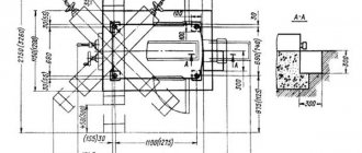
Installation drawing
The drawing is calculated individually depending on the room. The standard drawing is presented so that the equipment fits when rotated 45 degrees on any plane.
Limits of machine use in terms of power and power loads
The operating limits of the drive are determined only by the indicators of the electric motor installed in the equipment (if carried out at more than 63 revolutions per minute). If the number is less than 63, then the power of the main drive is reduced. The cutting force for longitudinal feed is a maximum of 1500 kgf, transverse - 1200 kgf, vertical - 500 kgf. The maximum workpiece size for roughing is up to 160 millimeters.
Advantages and disadvantages
The main positive characteristic of the machine is its versatility. All milling and drilling work is performed on it. Model 6P82 has advantages over other models:
- operator-friendly control;
- quick tool change;
- convenient table for fastening workpieces;
- several table feed speeds;
- built-in feed slowdown mechanism in automatic mode;
- automatic lubrication of components;
- mechanism for smoothly changing the feed speed;
- embedding the machine into automatic lines;
- Possibility of connecting CNC.
Reference! The machine has a push-button duplicate control panel for spindle and table movement.
It is convenient for the worker that the movement switch handles are turned to turn on in the direction of movement of the part.
Main advantages of the machine:
Constructive:
- mechanized tool fastening in the spindle;
- a device for periodically adjusting the size of the gap in the longitudinal feed screw pair;
- safety clutch protecting the feed drive from overloads;
- spindle braking when stopping using an electromagnetic clutch.
- various automatic machine operation cycles;
- wide range of spindle speeds and table feeds;
- high drive power;
- high rigidity;
- reliability and durability
Technological:
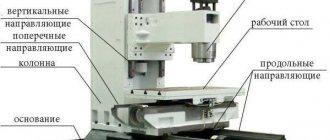
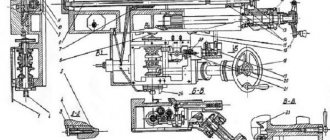
Design and its features
All working units are mounted directly on the cast machine bed. The spindle does not change its position and only moves forward during operation.
Trunk and earrings
The trunk moves horizontally, parallel to the spindle, along guides located in the upper part of the frame. A motor is installed in the rear part of the trunk body. It turns on when installed in front of the rotary head and rotates the tool installed in it.
When processing massive parts, the mandrel with the tool is fixed with earrings. They move along guides at the bottom of the trunk.
Gearbox
The gearbox is located directly in the hollow frame of the machine, in its upper part. An elastic coupling connects the gearbox to the electric motor shaft and at the same time eliminates misalignment of rotating parts.
To carry out inspection and maintenance of the gearbox, there is a special door on the right side of the frame.
Gearbox
The shift box is located directly above the gearbox, in the trunk. With its help, the required cutting mode is set using the handles located on the right, on the trunk body.
Gearbox
The console houses the feed box. The handles on the front wall of the unit set all feeds for movement in any direction. The feed drive is independent, powered by a motor located directly in the console body.
An adjustable ball clutch is built into the feed box. It protects against overloads by disconnecting the box from the motor shaft.
Overall dimensions of the workspace
Overall space is determined by the following parameters:
- table dimensions 1250×320 mm;
- maximum longitudinal movement 800 mm and transverse 240 mm;
- distance from the spindle axis to the table surface is 30–450 mm;
- the distance from the axis of the rotating spindle head to the frame guides is 260–280 mm.
One division of the dial is equal to a displacement of 0.05 mm in any direction.
Schedule and composition of repair and maintenance work
When the machine operates under normal operating conditions and compliance with all operating and maintenance rules specified in this manual, the overhaul cycle (service life before major repairs during two-shift operation) is (mainly) at least 9 years when processing steel (mainly), and at least 8 years for cast iron years.
Maintenance and repair work is recommended to be carried out according to the repair work schedule (Fig. 39).
| Parameter name | 6Р82 | 6R82G | 6Р83 | 6R83G |
| Cutter diameter, mm | 100 | 100 | 100 | 100 |
| Number of teeth | 8 | 8 | 8 | 8 |
| Milling width, mm | 100 | 100 | 150 | 150 |
| Milling depth, mm | 12 | 12 | 10 | 10 |
| Number of revolutions per minute, rpm | 50 | 50 | 50 | 50 |
| Longitudinal feed along the dial, mm/min | 125 | 125 | 125 | 125 |
In these modes, the clutch may periodically click.
The gap between the clutch discs is adjusted using nut 14, which is secured against spontaneous movement.
Schedule and composition of repair and maintenance work
When the machine operates under normal operating conditions and compliance with all operating and maintenance rules specified in this manual, the overhaul cycle (service life before major repairs during two-shift operation) is (mainly) at least 9 years when processing steel (mainly), and at least 8 years for cast iron years.
Maintenance and repair work is recommended to be carried out according to the repair work schedule (Fig. 39).
Machine inspection
- External inspection of the machine (without disassembling to identify defects) of the condition and operation of the machine as a whole and by components;
- Inspection and check of the condition of the main movement and feed drive mechanisms;
- Adjusting the table lead screw clearances;
- Spindle bearing adjustment;
- Checking the operation of speed and feed switching mechanisms;
- Regulation of the mechanisms for switching on cam clutches and feeds and the high-speed friction clutch;
- Adjustment of table wedges, slides, console and trunk;
- Inspection of guides, cleaning of nicks and burrs;
- Tightening loose fasteners;
- Checking the operation of the limiting cams;
- Checking the condition and minor repairs of cooling and lubrication systems;
- Checking the condition and repairing protective devices;
- Identification of parts that require replacement during the next repair (starting with the second minor repair);
Small machine repair
- Partial disassembly of components;
- Flushing all components;
- Adjustment or replacement of rolling bearings;
- Cleaning burrs and nicks on gear teeth, crackers and shift forks;
- Replacement and addition of friction discs of the high-speed clutch (starting from the second repair);
- Scraping and cleaning of wedges and strips;
- Cleaning the lead screws and replacing worn nuts;
- Cleaning nicks and burrs on the guides and working surface of the table;
- Replacing worn and broken fasteners
- Checking and adjusting the mechanisms for switching on speeds and feeds;
- Repair of lubrication and cooling systems;
- Testing the machine at idle speed, checking for noise, heating and accuracy of the workpiece.
Average machine repair
- Unit disassembly of the machine;
- Flushing all components;
- Inspection of parts of disassembled units;
- Drawing up a list of defects;
- Adjusting or replacing spindle bearings;
- Replacement or restoration of spline shafts;
- Replacement of worn bushings and bearings;
- Replacement of discs and fastener clutch parts;
- Replacement of worn gears;
- Restoring or replacing worn lead screws and nuts;
- Scraping or replacing adjusting wedges;
- Repair of pumps and fittings of lubrication and cooling systems;
- Correction by scraping or grinding the surfaces of the guides if their wear exceeds the permissible level;
- Painting the external surfaces of the machine;
- Running in the machine at idle (at all speeds and feeds) with checking for noise and heating;
- Checking the machine for accuracy and rigidity according to GOST 17734-72.
Overhaul of the machine
Major repairs are carried out with complete disassembly of all components of the machine, based on the results of which a defective estimate sheet must be drawn up. As a result of the repair, all worn components and parts of the machine must be restored or replaced, and its original accuracy, rigidity and power must be restored. The nature and scope of work for this type of repair are determined for specific operating conditions by a unified system of scheduled preventive maintenance.
Operating instructions, passport
The operating manual contains the passport data for the machine, its purpose, and lists the main components with assembly drawings and detailing. The installation diagram of the machine and the rules for its operation are indicated.
The milling machine's passport can be downloaded for free from the link - Passport for a horizontal console milling machine with a rotary table 6P82.
The operating instructions contain a description of the control panels, the schematic arrangement of handles, and cutting modes. It lists the main causes of malfunctions and includes a lubrication diagram and bearing arrangement. The instructions describe the rules for operating the machine, including safety precautions.
The 6P82 horizontal milling console machine is easy to operate and reliable. These models are multifunctional and take up little space. They are suitable for repair shops and garage installations.
Kinematic diagram
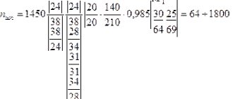
The kinematic diagram shows that the drive is connected to the electric motor through a coupling. It is responsible for transmitting movement to the structural unit. The transformations of the three blocks determine the number of spindle revolutions. Communication up to 13 speeds is possible, without the need to change in stages.
To read: What is special about CNC machines for cutting foam plastic
An electric motor located in the console acts as a gear drive. This happens by one of 18 different feeds through the jaw coupling to the screws. Those, in turn, on a horizontal mill can be of three types: vertical, longitudinal and transverse.
The function of the travel friction is important, which carries out movements through the gears before the feeds. This part is connected to the coupling, simultaneous functionality is limited. The frame is fixed with pins according to the scheme, fixed in a rigid way.