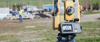
For goniometric measurements, without which not a single geodetic or theodolite survey is complete, as well as general construction work of industrial volumes or modest private construction, the UOMZ 3T5KP theodolite of serial production 3T, which is an optical type instrument, is used.
Its main purpose is to determine the directions and values of horizontal and vertical angles; in addition to this function, this tool is capable of:
- measure distances with a thread rangefinder;
- determine magnetic azimuths on the ground using a reference compass;
- perform geometric leveling;
- create a plan-height survey justification.
An easy-to-use device with a fairly simple design is used in various fields where the necessary, not very high accuracy of calculations is required (the model has a goniometric accuracy of 5 minutes):
- general civil and housing construction of buildings and infrastructure of various types;
- forestry and agriculture, execution of theodolite and tacheometric traverses;
- expeditionary and field conditions;
- geodetic and survey condensation networks;
- surface surveying and mining;
- other areas of exploration work.
The manufacturer has specified a warranty period of 2 years.
Device structure
Knowledge of the symbols that form the marking of the device will allow you to select a theodolite with the characteristics and functions required for operation. Theodolite marking “3T5KP” is deciphered as follows:
- “3” is an instrument of the third, quite progressive generation, which has significant modifications compared to younger models;
- “T” - Russian theodolite - standard accuracy class, determining the error in minutes; the accuracy of angular measurements classifies the 3T5KP model as a precision type device;
- “K” - indicates that the theodolite structure is equipped with an automatic compensator, which aligns the axes of the device when deviating from the working position within acceptable limits;
- “P” - a special telescope device forms a familiar direct format image.
There is no micrometer in the design of the model.
The instrument's telescope is characterized by a fairly high zoom level – 30-fold. The image is formed in a direct way with sufficient contrast and clarity that is comfortable for the visual organs of the specialist servicing the device.
The model uses a scale reading microscope with a division value of 1′.
The basic, standard package includes:
- theodolite with a tribrach stand;
- attachments for the lens and attachments for the eyepieces of the reading microscope and optical tube;
- a set of tools for adjustment (pin and screwdrivers large and small);
- technical documentation: operating instructions for theodolite 3T5KP, technical passport, factory certificate of state verification;
- transport case.
A compass for determining magnetic azimuths on the ground and a sighting pole inserted into the theodolite handle designed for carrying are supplied optionally.
Popular devices
The modern market offers many models of electronic theodolites. Among the most popular devices are:
- DJD2-GH is an accurate device, the mean square error of which is 2. A two-line graphic monitor and control panel are located on different sides of the alidade. The vertical and horizontal angle data is displayed simultaneously on the monitor. The 30x tube provides a direct image. Thanks to the built-in backlight, the device can be used even in poor lighting conditions.
- ADADigiTeo 10 with a dust and waterproof housing and a two-sided LCD screen, the numbers on which are visible in any position of the device. The angular accuracy of the telescope when zoomed by 30 times reaches 10, the picture is straight. The presence of a code dial minimizes inaccuracies when reading data.
- DT-205 with a removable tribrach to facilitate installation of the device at travel stations. Refers to construction theodolites (angular accuracy is 5). The reading results are displayed on a sectional double monitor with backlight. Information is transferred to external data storage elements or a PC using a COM port.
Specifications
| Mean square error of one measurement | 5" (same value for horizontal and vertical angles) |
| Vertical angle measurement range | +60…-55° |
| Approaching the sighting scope | 30 times |
| Image | direct |
| Compensator | present, the compensator operating range is ±4′ |
| Reading device | scale system with 1′ divisions |
| Operating temperature range | -40 … +50°С |
| dimensions | 183×123×345 mm |
| Weight with tribrach | 4.4 kg |
The 3T5KP theodolite user manual can be found at the following link.
Principle and features of devices
The most important difference between electronic theodolites and optical devices is the use of a binary digital measuring system with full rotation angle sensors. Its essence lies in marking the photoelectric disk with an algorithm of black and white code marks, when illuminated, the result is 1 or 0. This value is subsequently analyzed and processed in the processor. The captured information is recorded in an integrated storage element or transferred to external media or a PC.
The main components of electric theodolites are:
- laser or optical plummet;
- stand with tribrach;
- graphic LCD screen with control panel for the most important actions;
- a visual optical tube with a network of threads for high-quality positioning on an object;
- screws for fastening, adjustment and alignment;
- high-strength housing with a reference system housed in it.
Modern models, as a rule, are equipped with vertical compensators, which greatly simplifies the work with the device.
Basics of operation and storage
Before using a geodetic instrument, it is necessary to check its stability on a tripod, the movement of the screw system must be smooth and small, and the fixing screws must be reliable. Bringing the theodolite into working position, centering, is performed using an optical plumb line.
The wide, in contrast to similar foreign-made models, range of operating temperatures (from -40 to +50°C) is due to the absence of electronic elements in the design of the device. The optical observation system does not require the use of batteries or other power supplies, which makes the device completely mobile and ensures the feasibility of long-term continuous operation.
The vertical circle compensator allows for quick and accurate measurements. A well-thought-out design and connection for the use of additional equipment makes the 3T5KP theodolite a multifunctional device.
The design of all devices of the UOMZ 3T series without exception allows the installation of light rangefinders from the same manufacturer.
When receiving the device from another owner, after repair, long-term storage and before performing high-precision work, it is necessary to perform a set of verifications. Verifications are designed to determine the compliance of the existing parameters of the device and its characteristics declared by the manufacturer.
Discrepancies in the case of verifications will have a negative impact on the quality of the work performed, and therefore must be corrected by adjustment (regulation). If this does not lead to the desired result, the device is unsuitable for further use, since it cannot provide the necessary accuracy of work.
It is recommended to store the device in a clean room at positive temperatures +5...+40° and relative humidity no more than 65%. The air environment of the room should not be aggressive and conducive to rusting and corrosion of metal parts, as well as the appearance of plaque on the elements of the optical system. It is also necessary to exclude thermal effects: central heating radiators, direct sunlight, open fire sources, etc.
The average cost of a 3T5KP theodolite in the Russian Federation varies from 50,000 to 60,000 rubles.
Measuring distances with a theodolite
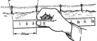
Distances are measured using a theodolite using a special rangefinder rod 3 m long, 7-8 cm wide, 3 cm thick, the front side of which is divided into segments measuring 50, 10 and 2 cm as shown in Fig. 3.7.
To measure distance, install a theodolite at one end and a rod at the other end of the line being measured. The upper or lower thread of the telescope reticle is aligned with the beginning of the meter or half-meter division (depending on the length of the line being measured) and the number of divisions of the staff between the rangefinder reticle threads is counted. If one large division (50 cm) of the staff fits between the strokes of the thread rangefinder, then the measured distance is 50 m (the rangefinder coefficient is 100). A checker of five divisions (10 cm) of the staff corresponds to 10 m, a small division of the staff (2 cm) corresponds to 2 m. In Fig. 3.7 the reading on the staff is 103 m.
Using a theodolite, you can measure distances from 50 to 300 m. The accuracy of measuring distances using a theodolite is characterized by a relative median error of 1: 300-1: 400. When measuring inclined lines using a theodolite (at angles of inclination exceeding 5°), the measured distance leads to horizon by introducing a correction
↑ Measurement of horizontal angles and inclination angles PAB-2
Horizontal angles are measured using a compass in one or two half-measures. When measuring an angle using two half-measures, the operating procedure is as follows:
The first half-technique - when installing a bead-sol ring at random, the vertical thread of the bead-sol monocular is sequentially pointed first at the right and then at the left object; at each pointing, a count is taken from the compass ring and drum and recorded in a journal (Diagram 3.4).
The second half technique is to turn the compass with the drum of the adjusting worm to an arbitrary angle, after which pointing at the right and left objects is repeated, taking readings.
In both half-techniques, the value of the horizontal angle is determined as the difference in readings for the right and left objects.
The discrepancy in the angle values in the first and second half* techniques should not exceed 0-01.
To measure the angle of inclination, it is enough to align the horizontal thread of the compass monocular with the point of sight and take a reading on the reference puck and the vertical aiming drum. In this case, it is necessary that the bubble of the ball level is in the middle.
For positive elevation angles, the reading is taken from the upper (red) numbers of the drum scale; for negative elevation angles, the reading is taken from the lower (black) numbers.
↑ Measuring distances
Distances using a compass are measured using the rangefinder scales of a monocular using a constant base—a two-meter staff—or using a sighting rod using the goniometric scales of a monocular as a rangefinder with a constant angle. To measure distances on rangefinder scales, the rod is installed horizontally or vertically, depending on the terrain conditions.
To measure the distance along a horizontal rod, a compass is installed at one end of the distance being measured, and a rod is installed at the other end so that it is located perpendicular to the observation line. By rotating the handwheel of the reference (setting) worm and the drum of the vertical aiming mechanism, install the monocular so that the image of the staff is located under the horizontal rangefinder scale, and combine the right (non-digitized) stroke of the rangefinder scale with the right mark of the staff. The value of the measured distance is read from the rangefinder scale against the left mark of the staff.
When measuring distance along a vertically installed staff, the image of the staff is placed to the left of the vertical rangefinder scale, and the upper (non-digitized) line of the scale is aligned with the center of the upper mark of the staff and the distance on the scale is counted against the center of the lower mark. An example of distance measurement using a vertically mounted staff and a vertical rangefinder scale is shown in Fig. 3.15. The measured distance is 160 m.
To measure a distance using a sighting rod, it is necessary to count the number of divisions of the sighting rod installed at the end of the measured distance, enclosed between adjacent elongated strokes (0-10) of the goniometric grid, and calculate the distance using the formula d=\Qn, where n is the number of decimeter divisions of the pole.
Example 1. In the 0-10 grid division, 9.6 pole divisions fit. Measured distance d—10 -9.6=96 m.
When measuring the distance along adjacent grid lines (0-05), the value obtained from the above formula is multiplied by 2.
Example 2. Between adjacent grid strokes (0-05) 5 pole divisions fit. Measured distance d=2-10-5 = 100 m.
The accuracy of measuring a line using a compass depending on the distance is characterized by a relative median error equal to 1: 100–1: 150.
Basics of geodesy
A device for measuring horizontal and vertical angles on the ground is called a theodolite.
In the first theodolites, in the center of the goniometer circle, on the tip of the needle, a ruler was placed, which could rotate freely on this tip (like the needle on a compass); Cutouts were made in the ruler and threads were stretched in them, playing the role of reference indexes. The center of the goniometer circle was placed at the vertex of the angle being measured and it was securely fixed. Rotating the ruler, aligned it with the first side of the angle and took reading N1 on the scale of the goniometer circle. Then the ruler was aligned with the second side of the angle and reading N2 was taken. The difference between N2 and N1 readings is equal to the angle value. The movable ruler was called an alidade, and the goniometric circle itself was called a limb. To align the alidade ruler with the sides of the angle, primitive sights were used.
Modern theodolites, while retaining the idea of measuring angles, are structurally significantly different from ancient theodolites. First, to align the alidade with the sides of the angle, a telescope is used, which can be rotated in height and azimuth; secondly, there is a reading device for reading on the dial scale, thirdly, the entire structure of the theodolite is covered with a durable metal casing, etc. For smooth rotation of the alidade and limb there is a system of axes, and the rotations themselves are regulated by clamping and guide screws. To install the theodolite on the ground, a special tripod is used, and the center of the limb is aligned with a plumb line passing through the top of the angle being measured using an optical plummet or a plumb line.
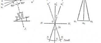
The sides of the angle being measured are projected onto the limb plane by a movable vertical plane, which is called the collimation plane. The collimation plane is formed by the sighting axis of the telescope when the telescope rotates around its axis.
The sighting axis of the tube (or sighting line) is an imaginary line passing through the center of the reticle and the optical center of the tube lens.
Let us list the main parts of the theodolite (Fig. 4.4):
Limb is a goniometric circle with divisions from 0o to 360o; when measuring angles, the dial is a working measure (not shown in Fig. 4.4).
Alidade is a movable part of the theodolite, carrying a dial reading system and a sighting device - a telescope. Usually the entire rotating part of the theodolite is called the alidade part or simply the alidade (2 in Fig. 4.4).
The telescope is mounted on stands on the alidade part (3).
Axle system – ensures rotation of the alidade part and the limb around a vertical axis.
The vertical circle is used to measure vertical angles (4).
Stand with three lifting screws (5).
Clamping and guiding screws of the rotating parts of the theodolite: limb (8,9), alidade (6,7), pipes (10,11); clamping screws are also called fastening and locking screws, and guiding screws are called micrometer screws.
A tripod with a hook for a plumb line, a platform for installing a theodolite stand and a mounting screw.
12 – dial adjustment screw; 13 – level for alidade of a horizontal circle; 14 – level of the vertical circle; 15 – tube focusing screw; 16 – eyepiece of the microscope of the reading device.
Fig.4.4
There are three different rotations in theodolites: telescope rotation, alidade rotation, and limb rotation; in this case, the rotation of the pipe and the rotation of the alidade are supplied with two screws each - clamping and guiding. As for the rotation of the limb, it is designed in different ways. In repeating theodolites, the dial can only rotate together with the alidade; in the T30 (2T30, etc.) theodolite there are two screws for rotating the dial: clamping and guiding, and they only work when the alidade screw is clamped. In the T15 theodolite of the first releases, the dial was fastened to the alidade using a special latch, and in this position, the joint rotation of the alidade and the dial was regulated by the alidade screws. In precise and high-precision theodolites, rotation (rearrangement) of the dial is performed with a special endless screw (position 12 in Fig. 4.4-b).
Recommend Google:
Benefits of use
The main advantages of using electronic theodolites include:
- automatic calculation and recording of reference information;
- minimizing errors in determining readings (which is typical for optical models);
- Possibility of operation in the dark in the presence of a laser pointer and illumination of the monitor microscale.
The use of devices in field conditions is limited due to the impossibility of their operation without batteries and recharging. Also, the electronic elements of the device (monitor, microprocessor, sensors) do not function at low temperatures.
Types and classification
Just like other types of theodolites (optical and laser), their electronic assemblies are divided according to the mean square error (MSE):
- high-precision or engineering (RMS indicator is 0.5''-1'');
- precision or construction (2''-10'');
- technical (15''-30'').
Structurally, an electronic theodolite can be made:
- with or without the use of a vertical circle compensator (which is displayed in the device marking with the letter “K” - compensator);
- using an optical or laser plumb line.
Working with an electronic theodolite of any type does not present any particular difficulties: modern instruments provide the convenience of taking readings, which allows you to comfortably work with them even without special skills, having undergone minimal instruction.
