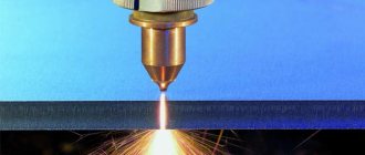
Seam roller welding helps to make sealed containers and weld metal without surfacing materials. Accurate point connection can withstand heavy loads. Using special equipment, a sealed seam is obtained that does not allow liquids and gases to pass through. Roller technology, like all other types of welding, has its advantages and disadvantages. It is worth talking about them in detail. But first, a few words about the essence of the method of seam joining metal sheets.
Content
- Definitions and diagrams of spot and seam welding
- Spot resistance welding
- Seam (roller) resistance welding
- Plastic deformation in the welding zone
- Technological capabilities of spot and seam welding
- Spot and seam resistance welding technology
- Requirements for welded structures
- Preparation for welding
- Preparing the surfaces of parts
- Assembling parts for welding
- Tack parts
- Classification of welding machines
- Electrodes of welding machines
- Mechanization and automation of seam and spot welding
Spot and seam (roller) resistance welding are the most popular and common methods of resistance welding. Approximately 90% of all welded joints created using resistance welding are spot and seam (roller) welding, because in these methods of joining parts, the advantages of resistance welding given on this page are most fully manifested. Next, we will consider the essence, technology of each of these types of welding and the equipment necessary for this.
Operating principle
The technology of resistance welding by spot, seam and relief methods is based on the same single operation - creating a weld point at the point of contact of the surfaces of the workpieces. In general it looks like this (see figure below):
- Installation of overlapping workpieces on the lower electrode.
- Compressing them with the upper electrode.
- Supply of a welding current pulse.
- Briefly hold the compression until the weld spot cools.
- Retracting the upper electrode to its original position.
Resistance welding installations use direct current of reverse polarity (plus to the top electrode) or alternating current at a frequency of 50 Hz (in some cases, high-frequency sources are used)
Pressing parts is an important part of the technological process. After the passage of a current pulse, a lens of molten metal appears at the point of contact between the surfaces of the parts, which in contact technology is called a core. Compression with the necessary force does not allow the metal to splash out beyond the core area, and also causes plastic deformation of the core area and mutual penetration of the metals of the workpieces
Compression with the necessary force does not allow the metal to splash out beyond the core region, and also causes plastic deformation of the core zone and mutual penetration of the metals of the workpieces.
A standard spot welding setup consists of the following elements (see figure below):
- AC or DC power supply;
- lower (support) handle with a ground electrode;
- upper (pressure) handle with the main electrode;
- installation housing with a clamping mechanism and contacts.
Butt welding technology differs from other contact methods, because in this case, the end parts of two massive parts are connected by melting metal. The sequence of technological operations for resistance butt welding is as follows (see figure below):
- Fixing one of the workpieces in a stationary clamping device.
- Installation of the second workpiece into the movable equipment.
- Compression of the ends of workpieces with constant force.
- Supplying a welding current pulse to the workpiece.
- Heating the metal to a melting state with continued application of force after the current is turned off.
- Bringing the ends together and forming a weld.
- Cooling of the seam and removal of stress.
The open circuit voltage in resistance welding devices is much lower than that of other welding equipment. Typically it is 3÷6 V (maximum up to 20 V), while the welding voltage is 1÷1.5 V. The current strength in all contact methods, depending on the thickness of the workpieces and the contact area, ranges from a few to hundreds of thousands of amperes. The penetration depth of each part, depending on the type of material, should be from 20 to 80% percent of its thickness. Through penetration (burning) of the metal is not allowed, as well as its penetration to a depth less than the norm.
Definitions, features and diagrams of spot and seam welding
Spot resistance welding
Spot welding is a type of contact welding in which welding of parts occurs in separate areas of contact at several points with a certain step.
Figure a) on the left shows a spot welding diagram. The parts to be welded (item 1) are overlapped and placed between the electrodes (item 2) of the welding machine. One of the electrodes begins to move and acts on the part with a force Fst. After some time necessary to ensure reliable electrical contact, an electric current of 5-6 V is supplied to the electrodes from the secondary winding of the welding transformer (item 3) or rectifier. A short-term powerful pulse of welding current, lasting 0.01-0.1 s, provides very fast, almost instantaneous heating and the formation of a melting zone - a liquid core (item 4), common to both parts.
Heating is accompanied by plastic deformation of the metal during welding and a sealing belt is formed around the liquid core (item 5), which protects the liquid metal from splashing and interaction with the environment. Therefore, a special layer of protection, for example, as when welding in a carbon dioxide environment or in an argon environment, is not required.
After the current supply is stopped, the liquid metal quickly cools and crystallizes, and a strong metallic bond is formed between the parts. The force from the electrodes is not removed immediately, but after some time, which ensures crystallization under pressure - forging and the absence of defects in the weld (hot and cold cracks, shrinkage cavities, residual stresses). In some cases, the impact force at this stage of the process is increased by 2-3 times, i.e., in fact, forging force is used.
To increase welding productivity, a protrusion is preliminarily formed on one of the parts (item 6 in diagram b). The shape of the protrusion is semicircular or trapezoidal. This method is called spot relief welding. The protrusion limits the initial contact area, making it possible to increase the current density in the part-to-part contact area, using electrodes with a large surface area. As a result of heating, the protrusion is gradually deformed and at the end of the process a core is obtained, as in conventional spot welding. You can weld simultaneously on several protrusions.
If access of the electrodes to one of the parts is difficult, then it is advisable to use one-sided spot welding. Its diagram is shown in diagram c) of the figure on the left. In this case, the parts assembled for welding are installed on a copper lining (item 7) and the parts are pressed against it by two electrodes located on the side of one of the parts.
Seam (roller) resistance welding
Seam welding is a contact welding method in which current is supplied and parts are moved using rotating disk electrodes-rollers (item 8 in diagram d); the name roller welding is also common. As with spot welding, the metal is heated using short-term pulses of electric current, repeated at regular intervals. As a result, a series of points is formed. If the gap between pulses is small enough, the points overlap, forming a sealed weld.
There are continuous and step resistance welding. During continuous welding, the rollers rotate without stopping, and during step welding, the rollers stop at the moment the current pulse passes and the joint is forged, which reduces wear of the rollers, residual stresses and deformation during welding and reduces the tendency to form defects in the weld, especially hot cracks and shells.
In most cases, seam welding parts are assembled overlapping, but butt welding is also used, which provides greater strength to the welded joints (diagram e). For such welding, foil pads (item 9) are often used to obtain complete penetration of the parts being welded.
Plastic deformation in the welding zone
Plastic deformation of the metal being welded is one of the features of all types of resistance welding. At the first stage, mainly deformation of microroughness occurs, the degree of which in the contact of parts reaches up to 70%. This deformation is alleviated if increased crimping forces or additional electrical impulses are used at this stage to form good electrical contact. When current is applied, the metal rapidly heats up, its resistance to plastic deformation decreases, and the rate of microplastic deformation increases and by the time the metal begins to melt, the degree of its deformation approaches 100%.
From the moment of heating, volumetric plastic deformation of the metal begins to develop. The reason for its occurrence is external (welding) force and internally, associated with an uneven temperature field and unfree thermal expansion of the metal. These forces cause uneven volumetric compression of the metal in the welding zone.
At the stage of cooling and crystallization, a reduction in the volume of the metal occurs and residual tensile stresses are formed in the welding zone, which can lead to the formation of cold cracks in the metal and reduce the performance characteristics of the structure.
The peculiarity of metal deformation during cooling is that the volume of the metal contracts most quickly near the axis, as a result of which the pressure in the center decreases and the possibility of reverse deformation arises - from the edge of the joint to its center. Reverse deformation helps reduce stress and the tendency to form discontinuities, especially when increased forging forces are applied at this stage.
At the end of the welding process, dents remain on the surface of the seam, with a depth of 10-15% of the thickness of the metal being welded.
It is believed that one of the conditions for a stable welding process (no metal splash) is a certain degree of plastic deformation. The degree of this deformation increases with the use of increased welding forces, the use of soft modes, preheating of parts and other technological methods.
The most severe degree of deformation appears during projection welding immediately after turning on the current. In some cases, the flow of metal along the surface of the parts can ensure their strong connection without melting in the annular zone along the periphery of the contact (see diagram b in the figure above).
Plastic deformation during resistance welding does not remove oxide films from metal surfaces. Only at the initial stage does microplastic deformation contribute to the destruction of these films. The final removal of their parts occurs in the molten metal under the influence of electrodynamic forces.
Technological capabilities of spot and seam resistance welding
Spot and seam (roller) types of resistance welding have wide technological capabilities, as they allow connecting almost all structural materials with a wide range of thicknesses.
In practice, resistance welding of copper and copper alloys, titanium and magnesium welding, aluminum welding, welding of nickel and nickel alloys, and alloy steels are widely used. Some difficulties arise when welding refractory metals, for example, molybdenum, and they are associated with the low resistance of the electrodes due to the high temperature on their working surface.
In addition, it is possible to weld metals with anti-corrosion coating - galvanized, aluminized and nickel-plated steels and even metals with non-metallic insulating coatings, as well as composite materials. But, when connecting all of the listed dissimilar materials, it should be borne in mind that spot welding is allowed for welding only homogeneous materials or alloys on the same base, for example, welding low-carbon steel with corrosion-resistant steel. When welding dissimilar materials using this method, in particular magnesium with aluminum, a large amount of intermetallic compounds is formed in the weld, and the mechanical properties of the joint will be low.
The range of welded thicknesses is 20 µm - 30 mm for spot welding and 8-10 mm for seam welding. Most often, metals of the same thickness are welded, but it is possible to weld parts of different thicknesses, and the thickness of one of them can be 20 or more times greater than the other. Welded joints have very high strength values. At the same time, the tear strength of the points is 2-4 times less than the shear strength.
Essence of the process
The resistance welding process is based on short-term exposure to current of varying strength. As it passes through the metal, it heats up, thereby significantly increasing the degree of ductility. The main positive features include the following:
- When using the technology under consideration, heat is generated in the body of the workpiece itself. In order to eliminate the possibility of heat spreading throughout the material, its feed rate must be high. That is why special welding equipment is used.
- The supplied current should be high and the heating time should be short. As practice shows, the power during the processing in question amounts to several hundred and even thousands of Amperes. In this case, the exposure time is only a few fractions of seconds. A similar result can only be achieved with internal heat generation in the material.
- The equipment used can significantly increase productivity. Many people call this point an advantage of contact welding. Today, robotic technology is being created that welds large amounts of metal by applying current.
- The processing takes place without the use of filler metal. That is why the technology is considered more economical in terms of the amount of energy consumed.
- Heating occurs directly in the affected area. This is why there are no heat losses when compared with manual arc welding or other technologies.
- The equipment used greatly facilitates the process. In this case, you can use equipment that automates processing. At the moment of exposure to current, a bright flash does not form, therefore, the cost of equipment in the treatment area is reduced.
Spot welding in production
Today, resistance welding is used in the case of conveyor production. Robots can join metal virtually continuously.
We should not forget about some of the disadvantages of resistance welding. It also defines the features of the technology in question. The disadvantages are as follows:
- In order to ensure high quality joints, equipment must be used that can apply pressure to the workpiece.
- The connection can only be carried out if the workpieces can be placed in a special machine. In other words, there are certain restrictions on the size of products.
- If the seam must be large, then the mechanical power and the strength of the supplied current increase significantly. In addition, there are certain restrictions regarding the thickness of the elements being connected.
- The technology is not characterized by versatility and maneuverability. In other words, it is quite difficult to carry out work at the site where the products are placed; for this purpose, home-made structures are often created.
- The resulting seam is characterized by low tightness.
Spot resistance welding
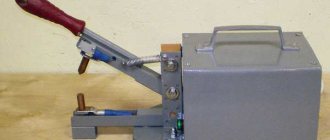
In addition, purchased equipment is characterized by high cost. Serious problems may arise during maintenance. If desired, you can create a homemade design that is highly efficient.
Spot and seam resistance welding technology
Requirements for welded structures
One of the main requirements is the possibility of easy access of electrodes to the welding zone (assemblies of the “open” or “semi-open” type). Open panels are most convenient for welding; box-shaped units, shells, small-diameter pipes, and others are the least convenient.
Typically, sheet and profile parts are connected by spot and seam welding. If the product does not have tightness requirements, then spot welding is used. If strong and tight seams are needed, seam welding is used. If access to the welding zone is difficult, then one-sided welding is used.
According to GOST 15878, the main structural elements of connections for groups A and B are distinguished, see the figure above. Group A compounds have greater strength due to their large core diameter. The strength and tightness of welds are most influenced by the diameter of the core (for spot resistance welding) and the width of the seam (for seam resistance welding). The actual diametrical size of the core must be no less than indicated in the table below:
When setting up the mode, the core diameter is set 15-25% higher than that indicated in the table in order to compensate for fluctuations in various mode parameters, for example, a decrease in current strength, the condition of the surfaces of parts, etc. Modern welding machines make it possible in some cases to reduce the core diameter by 20 -thirty%.
The penetration depth (relative core height) is 20-80% of the part thickness. But when welding titanium alloys, due to their low thermal conductivity, the penetration depth can reach 95%. On average, for most alloys it is 50%.
The dent depth g should not exceed 20% of the thickness of the parts if they are of equal thickness. If parts of different thicknesses are welded, the dent on a thin part can reach 30%.
The minimum distance (step) between the centers of adjacent points tsh is selected from the conditions for limiting current shunting while maintaining high weld strength.
The overlap of the cast zones of the sealed seam f should be 25% of the length of the cast zone l, or slightly more. On average, the overlap is 50%.
The maximum overlap value B is the smallest value of the mating part of the parts being connected. The distance between the axes of adjacent rows C is 20% greater than the pitch.
The dimensions of structural elements increase as the thickness of the parts increases. When welding parts of different thicknesses, the dimensions are selected based on the thinner part.
Relief welding is most often used when welding steel parts, and up to 20 reliefs can be welded in one pulse. The main types of reliefs used in practice are shown in the figure below:
The dimensions of spherical reliefs, shapes of punches and matrices are shown in the figure below:
In this case, the core diameter, in most cases, is 20-50% greater than the dр value. Tolerances for the height and diameter of the relief are ±0.05 and 0.1 mm if the thickness of the parts does not exceed 1.25 mm and ±0.12 if the thickness of the parts exceeds 1.25 mm. The connection dimensions are shown in the table:
Preparation for welding
The technological process of manufacturing welded assemblies includes a number of different operations performed in strict sequence. To obtain a high-quality connection, preparatory operations are very important: surface preparation, assembly and tack welding.
Preparing the surfaces of parts
The purpose of this operation is to clean the welded areas from oxide films. To do this, two stages of surface cleaning are carried out. First, the surface is degreased in solutions of sodium carbonate (for welding titanium and alloy steels) or in alkali solutions and organic solvents (for welding aluminum, magnesium and their alloys). Low-carbon steels in mass production are often not degreased.
Next, the oxide films are removed chemically or mechanically. Mechanical processing is carried out with cast iron or steel shot (only for welding steel and titanium parts) or mechanical brushes (this method is suitable for most welded materials). Mechanical cleaning methods are quite universal, but very limited due to the high activity of the surface. The shelf life, for example, for aluminum and magnesium alloys is 1-5 days, depending on storage conditions.
Chemical processing is used for all metals and allows you to obtain a fairly clean and relatively low-active surface. For example, the shelf life of processed aluminum and magnesium parts is 15-30 days.
Assembling parts for welding
When assembling the parts, their mutual arrangement is achieved, ensuring minimal gaps between them. If parts are not interchangeable, they are adjusted during pre-assembly, followed by surface preparation and final assembly.
Large gaps increase the likelihood of defects in the weld such as lack of penetration, general warping of the weld, and splashes of liquid metal. The permissible gap size depends on the welding mode, the rigidity of the structure being welded and the length of the gap. If the thickness of the parts being welded is 1 mm in normal modes, the gaps should not exceed 0.4 mm for a length of 100 mm and 1.2 mm for a length of 300 mm.
If the thickness of the parts is 3mm, the gaps must be reduced to 0.3 and 0.9mm, respectively. Assembly is carried out according to markings, using templates and special devices.
Tack parts
This operation is necessary to ensure accurate fixation of the parts being welded and to reduce residual deformations after welding. Tacks are performed with a certain step at individual points. For spot resistance welding, the tack spacing is 10-30cm, for seam welding - 2.5-10cm.
To reduce warping of the welded unit, tack welding is performed in a certain sequence. The sequence of tack welding on some types of construction is shown in the figure:
Selecting welding modes
In spot and seam resistance welding, there are many possibilities for controlling the thermal deformation cycle, for example, by changing the modes at the heating and cooling stages, thus minimizing changes in the structure and properties of the source material, the formation of residual stresses and wear of the working surface of the electrodes.
The main indicators of the welding mode at the heating stage include the current strength, the time of its exposure and the welding force. At the cooling stage - the forging force and the time of its application. The values of one or another parameter can be constant or change at each stage according to a specific program. This, first of all, depends on the properties of the metal being welded and its thickness. For example, with increasing metal thickness, the core diameter increases and other parameters increase. Approximate welding modes for certain metals and alloys are presented in the tables below:
Treatment of joints after welding
To increase cyclic strength, in some cases, after spot contact welding, cold or hot hardening adhesive is introduced under the overlap (in the latter case, heat treatment at a temperature of 120-170°C is required). Instead of applying glue, the welded joint is often soldered with copper or silver solders on components made of titanium and heat-resistant alloys. Using this technique, they achieve an increase in cyclic strength by 2-3 times and corrosion resistance due to sealing the gap.
If the degree of warping of the welded joint is unacceptable, the joint is heated and straightening is performed using external force. Assemblies with base and seating surfaces in some cases undergo mechanical processing (milling, turning, etc.).
Electrode designs
Electrodes are also used to work with electric arc welding, but they are fundamentally different from the conductive elements for contact welding, and are not suitable for this type of work. Since at the time of welding the parts are compressed by the contact parts of the welding machine, electrodes for resistance welding are able to conduct electric current, withstand compression loads and remove heat.
The metal being welded determines the shape of the electrode used. These elements, which have a flat working surface, are used for welding conventional steels. The spherical shape is ideal for joining copper, aluminum, high carbon and alloy steels.
The spherical shape is most resistant to combustion. Due to their shape, they are able to make a larger number of welds before sharpening. In addition, the use of this form allows you to weld any metal. At the same time, if you weld aluminum or magnesium with a flat surface, dents will form.
Electrode diagram for welding
The electrode seat is often cone-shaped or threaded. This design avoids current losses and effectively compresses parts. The landing cone can be short, but they are used with low forces and low currents. If a threaded fastener is used, it is often through a union nut. Threaded fastening is especially important in special multi-point machines, since the same gap between the claws is required.
To perform welding deep into the part, electrodes of a curved configuration are used. There is a variety of curved shapes, so if you are constantly working in such conditions, it is necessary to have a selection of different shapes. However, they are inconvenient to use, and they have lower durability compared to straight ones, so they are used last.
Since the pressure on the shaped electrode is not along its axis, it is subject to bending during heating, and this must be kept in mind when choosing its shape. In addition, at such moments, it is possible that the working surface of the curved electrode may shift in relation to the flat one. Therefore, in such situations, a spherical working surface is usually used. Non-axial load also affects the seat of the electrode holder. Therefore, if there is excessive load, you need to use electrodes with an increased cone diameter.
When welding deep into a part, you can use a straight electrode if you tilt it vertically. However, the angle of inclination should be no more than 30°, since with a greater degree of inclination, deformation of the electrode holder occurs. In such situations, two curved conductive elements are used.
Appearance of electrodes
Using a clamp at the point where the shaped electrode is attached allows you to reduce the load on the cone and extend the service life of the welding machine seat. When developing a shaped electrode, you must first make a drawing, then make a test model from plasticine or wood, and only then begin its manufacture.
In industrial welding, cooling of the contact part is used. Often this cooling occurs through an internal channel, but if the electrode is of small diameter or increased heating occurs, then the coolant is supplied externally. However, external cooling is allowed provided that the parts being welded are not susceptible to corrosion.
The most difficult thing to cool is the shaped electrode due to its design. To cool it, thin copper tubes are used, which are located on the side parts. However, even under these conditions, it does not cool well enough, so it cannot cook at the same pace as a straight electrode. Otherwise, it overheats and its service life is reduced.
During resistance welding, the axis of the two electrodes should be 90° relative to the surface of the part. Therefore, when large-sized parts with a slope are welded, rotary, self-aligning holders are used, and welding is performed with a spherical working surface.
Steel mesh with a diameter of up to 5 mm is welded with a plate electrode. Uniform load distribution is achieved by free rotation of the upper conductive contact around its axis.
Although the spherical shape of the working surface is the most stable of the other shapes, it still loses its original shape due to thermal and power loads. If the working surface of the contact increases by 20% of the original size, then it is considered unusable and must be sharpened. Sharpening of resistance welding electrodes is carried out in accordance with GOST 14111.
Equipment for spot and seam contact welding
Modern equipment for spot and seam resistance welding is a set of elements for solving technological problems. The equipment includes the welding machine itself, means of mechanization and automation of welding processes and a control system for all these devices.
The diagram of the spot welding machine is shown in the figure above. The machine consists of two main parts. The first is mechanical with structural elements that provide rigidity and strength of the machine (body, bracket, etc.) and drives for transmitting force and moving parts. The second part is electrical, which includes a welding current source (welding transformer, rectifier, accumulators - capacitor banks, inverters - frequency converters, etc.) and a secondary circuit with current leads - consoles, electrical holders and electrodes.
Means of mechanization and automation are adaptations to universal machines or devices that ensure the preparation of a product for welding, assembly, tacking, installation, movement and removal of the unit.
A control system is necessary to set the work program (welding modes, sequence of operations, control and automatic adjustment of technological cycle parameters, collection and processing of information about the condition of equipment and product quality).
Classification of welding machines
Welding machines for resistance roller and seam welding are produced in different countries, but they can all be classified according to various criteria:
1. According to the welding method. There are machines for spot, relief and seam welding.
2. As intended. There are universal machines (general purpose) and specialized ones (usually by type of unit or assortment).
3. According to the installation method. There are stationary and mobile machines.
4. By type of food. There are AC machines, low-frequency and DC machines, and capacitor machines.
5. By type of force drive. Machines can be lever, spring, pneumatic, hydraulic, electromechanical, etc.
6. According to the degree of automation. The machines are non-automatic, semi-automatic and automatic.
Electrodes of welding machines
Electrodes of welding machines are a very important element, because the performance of turned and, especially, resistance seam welding depends on their durability. The basic requirements for electrode materials are set out in GOST 14111. For welding aluminum alloys and similar materials, these are, first of all, thermal and electrical conductivity. The requirements also include resistance to plastic deformation at temperatures of 300-500°C (for welding heat-resistant steels).
For the manufacture of electrodes, materials such as copper alloys are used. Pure refractory metals - molybdenum and tungsten - are used as electrode inserts. A separate group is represented by materials strengthened by particles of oxides (Al2O3, CrO3), carbides and nitrides, which have high heat resistance and electrical conductivity.
For welding copper alloys and aluminum alloys, electrode materials with high electrical conductivity are used, and for welding heat-resistant alloys - with high hardness at high temperatures (about 500°C).
Mechanization and automation of seam and spot contact welding
Welding machines for spot and seam contact welding provide almost complete automation of the process. To reduce the duration of auxiliary operations and increase the productivity of the entire process, various mechanized devices, automatic machines, automatic lines and industrial robots are used.
Assembly and welding devices include jigs, stocks, assembly stands, on which the assembly, tacking and welding of products is carried out. In practice, supporting (leveling) devices are also widely used, with the help of which you can orient the welded unit relative to the electrodes or rollers of the welding machine. An approximate diagram of such a device is shown in the figure.
Automatic lines are in demand in the automotive industry, in the production of agricultural machinery, in carriage building, in electronics, in the production of pipe blanks and in other areas of mass production.
Relief method
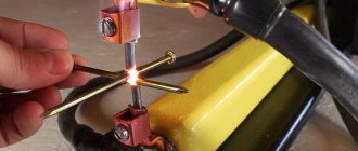
Relief welding is often used in the automotive industry to connect brackets with sheet elements (in particular, brackets are attached to the car hood and door hinges to the cab using the relief method), as well as for fixing standard fasteners - studs, bolts, nuts.
Regardless of the type of welding, the surfaces of the workpieces must be cleaned of dirt, corrosion, fuels and lubricants. However, relief welding requires additional preparation of products. Quite complex in shape (for example, round or oblong) protrusions must be made on them using special equipment.
Industrial applications of spot and seam welding
Due to the high productivity and quality of welded joints, these welding methods are among the most promising, primarily in mass production conditions. Among mechanized welding methods, contact welding confidently takes first place. This welding is most widely used in the automotive industry. It finds no less application in carriage building, when connecting the car skin to the frame.
Other areas of mass application are the production of combines and tractors, household appliances, electronics, sports equipment and in construction for the manufacture of building panels and frames. Spot and seam welding occupies a special place in the manufacture of metal structures for critical purposes, for example, in the production of modern airliners.
In instrument making, this type of welding is used to produce sensitive elements, instrument housings, and relays. In electronics in the manufacture of terminals of integrated circuits, conductors, electron-optical systems.
Relief welding is used in the manufacture of reinforced concrete reinforcement, meshes, gratings, connections of fasteners and fittings, studs with sheets, automobile brake pads, ball bearing cages, etc.
Using seam resistance welding, you can obtain strong connections that operate at high pressure and in high vacuum conditions, for example, fuel tanks of cars and agricultural machinery, drums of washing machines, refrigerator bodies and various containers (fire extinguishers, cans, siphons, etc.). At the same time, the welding speed of sealed seams reaches 10-15 m/min.
Quality control of welded joints
Welding quality control during seam and resistance spot welding is especially important, since the process proceeds very quickly and the nature of the formation of the joint is hidden from external observation. Various factors can lead to the formation of defects in a weld, such as lack of penetration. This includes the condition of the surfaces of parts and electrodes, the quality of assembly, and the variability of welding modes. In addition to lack of penetration, hot cracks, metal splashes and pitting may occur during welding.
Lack of penetration poses the greatest danger; they significantly reduce the performance characteristics of the connection, such as strength and tightness. External and internal metal splashes worsen the appearance of the product and can clog the lines. Cracks and cavities can mainly affect the tightness and, to a lesser extent, the strength, since they are located outside the zone of greatest operating stress.
When resistance welding, comprehensive control of joints is usually used, starting from monitoring equipment, fixtures, the condition of the surfaces of parts and electrodes, checking the quality of assembly and ending with monitoring the welded joint itself.
Control of the finished welded joint is a rather difficult task in resistance welding. For this purpose, the radiographic method of X-ray control is used. Using this non-destructive testing method, cracks, cavities, and splashes can be clearly identified.
Possible defects
During work, defects may occur that negatively affect the final result.
- Burn-through - this defect appears due to high voltage, due to a prolonged impulse or due to strong compression of parts. The overheated metal begins to drain, a hole is formed, and as a result, the welded edges can be easily torn off. To avoid this, you need to reduce the electric current supply and the clamping force.
- Metal splashing - during operation, sparks begin to fly from connection points. This occurs due to strong compression of the elements or due to weak impulse delivery for a long time. The metal begins to go beyond the contours of the “core”, and voids form in this place - the strength of the connection is compromised.
- Lack of penetration - appears due to weakly supplied current, insufficient clamping force or weakened tongs. Lack of penetration occurs if the welding points are nearby.
- Reduced weld size - occurs due to a short pulse or the parts were not tightly compressed.
In the next video you will find a modern process for spot welding metal objects.