What gases are used?
Gas welding uses flammable gases - natural, acetylene, gasoline vapor, hydrogen. These gases burn well in air without developing a high temperature; an oxygen stream is sufficient for combustion. Gas welding is most often carried out on the basis of acetylene, which is created on the basis of water and calcium carbide. It burns at a temperature of 3200-3400 degrees.
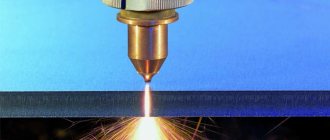
How to use a plasma cutter?
Experienced carvers have formulated a number of recommendations to make it easier for beginning craftsmen to master the technology:
- strictly maintain a constant distance from the burner to the workpiece;
- if necessary, use a stop that is attached to the side of the burner and limits the gap;
- operate the burner evenly, without jerking, at a given speed;
- monitor the perpendicularity of the plasma beam to the surface of the part; deviations lead to a decrease in the quality of the cut surface;
- monitor the beam of sparks flying from the back side of the part; if there are few of them or they disappear, the metal is not completely cut through and the cutting mode must be adjusted;
After completing the cut, the torch must be tilted to allow the gases accumulated in the hose to escape.
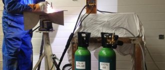
Oxygen reducer
When welding, oxygen comes from a special cylinder - it is painted blue or blue. To ensure normal operation, oxygen must enter the burner evenly and at low pressure. It is for these purposes that there is a reducer on the cylinders - it regulates the gas supply. In this case, hoses for gas welding - acetylene and oxygen - are supplied to the torch. Oxygen is supplied to the central channel, where the jet is more discharged, sucking in acetylene, which enters the burner under low pressure. The gases are mixed in the chamber and then released out of the tip.
4.1. Metal materials
4.1.1. Materials for working with acetylene and gases with similar chemical properties For the manufacture of parts in contact with gases, it is not allowed to use: – copper and alloys with a copper content of more than 65% (with the exception of mouthpieces and tips of torches and cutters); - materials containing copper (including metal-ceramic, fibrous and finely dispersed), - for flame-retardant, filtering, etc. elements with a large surface); - silver and its alloys (except for hard solders); - zinc (except for anti-corrosion coatings); - mercury; - magnesium. The content of silver and copper in hard solders should not exceed 46 and 37% by weight, respectively. Soldered joints must be designed in such a way that the area of contact between the seam and acetylene is as small as possible, and all flux residues after soldering can be removed. 4.1.2. Materials for working with oxygen All parts in contact with oxygen must be degreased. Springs and other moving parts in contact with oxygen must be made of oxidation-resistant materials and not have coatings. The springs of oxygen reducers may be coated with protective coatings that are resistant to oxygen.
Features of the technology
When performing gas welding, it is important to obtain a high-quality connection, so much attention is paid to careful preparation of the edges to be welded, choosing a method for joining the metal, installing the torch in the desired position and determining the required burner power parameters. Gas welding technology requires that the edges must be thoroughly cleaned of various contaminants. The bevel is performed using a manual or pneumatic chisel, and sometimes special machines are used. Scale and slag can be removed with a wire brush. Tacking the edges prevents their position from changing during welding.
Abstract to the book “Welding: A practical guide for electric and gas welders”
The book contains general information about welding, welded joints and seams, electric and gas fusion welding, gas welding and cutting. Devices, equipment and equipment for arc and gas welding, surfacing and cutting are briefly described, techniques for making various welds, and issues of quality control of welded joints are discussed. Information about promising types of welding is provided. For professional training and advanced training of welders, students of vocational schools and educational institutions, as well as for craftsmen and engineering personnel.
Other books by the author on Litres
Welding methods
Gas welding can be carried out in several ways. The first is left-hand welding, which is the most common. It is used when working with thin and low-melting metals. The torch moves from right to left, and the filler wire is driven in front of the flame, aimed at the unwelded area of the seam. In right-hand welding, the torch is moved from left to right, and the filler wire moves behind the torch. With this method, the heat of the flame is dissipated to a lesser extent, therefore the opening angle of the seam is not 90 degrees, but less - 60-70.
It is advisable to use right-hand welding to join metal whose thickness is from 3 mm and above, as well as metals with a high level of thermal conductivity. It is recommended to use filler wire whose diameter is equal to half the thickness of the metal being welded.
Gas welding technology also involves a process that is carried out with a through bead. In this case, the sheets are installed vertically to the gap - its size is equal to half the thickness of the sheet. Using a torch, melt the edges to create a round hole. It is then melted on all sides until the seam is welded. This method is good because the sheets being welded have a tight seam without pores or slag inclusions.
Pool welding is good for welding joints and corners of metals that have a maximum thickness of 3 mm. As soon as a pool is formed on the seam, the end of the filler wire is inserted into it, which melts slightly, then the end of the wire is moved to another section of the seam. The peculiarity of this approach is that the weld is of excellent quality, especially if thin sheets and pipes of steel (low-carbon and low-alloy) were welded.
Gas welding and cutting can be carried out on the basis of multilayer welding. This method has a number of features:
- heating zone is small;
- When surfacing subsequent layers, the underlying layers are simply annealed;
- each seam can be hammered before the next one is placed on it.
This affects the improvement of seam quality. On the other hand, this method is characterized by low productivity and requires high gas consumption compared to single-layer welding, so it is used when it is necessary to create responsible and high-quality products.
Purpose and scope
The use of a gas welding machine allows you to carry out the following operations:
- welding of various parts;
- soldering (including repair of damaged products);
- surfacing;
- cutting sheet metal and pipes into separate pieces.
The advantages of gas welding make it possible to use it in construction, industrial production, public utilities, car repair, and when solving everyday problems in dachas and country houses. Gas welding can join almost any material. It is used when connecting assemblies of products made of non-ferrous metals, thin-walled pipes, and elements of complex structures. With the right selection of conditions and solder, it is possible to weld cast iron and fuse brass onto its surface. Connecting and cutting metal elements allows you to obtain the required result of good quality.
Surfacing is intended for applying a metal of a different type or structure to the surface of the main product. In this case, the surface being treated is heated to the so-called fogging temperature. This method restores worn parts, increases their size, and deposits material with higher strength and wear characteristics. The use of surfacing increases the service life of parts, reduces the consumption of scarce materials, and reduces the cost of repairs.
Features of welding various seams
To work with horizontal seams, the right-hand method is used, which makes it possible to easily form a seam, and the metal of the bathtub itself does not drain. Welding of vertical and inclined seams is carried out using the left method, and if the metal thickness is above 5 mm, a double roller is used. Welding ceiling seams involves heating the edges until they melt, then inserting a filler wire into the pool - its end quickly melts. The process itself is carried out in the right way.
Technique of suturing in various spatial positions
Down position
Welding in the lower position is the simplest; in this case it is easiest to control the process of seam formation. The likelihood of lack of penetration and the appearance of other defects is reduced. The technique used is, as a rule, spiral-shaped movements of the end of the autogen mouthpiece. The additive is lowered into the heated weld pool, a “loop” is made and the operation is repeated. Each subsequent turn should overlap the previous one by 1/3 of the diameter.
Thin sheets are butt welded by flanging the edges, i.e. the edges of the workpieces are bent and welded without the use of filler wire. You can use both right and left connection methods.
Lap seams
Work should be carried out, if possible, without interruptions. If you pause, before repeating the process, melt the metal that has crystallized in the crater. Welding is carried out using the left-hand method with filler material. When working with this type of connection, it is more advisable to use arc technologies, as they are less expensive and more productive. This will especially affect large volumes.
Vertical position
Possible options for making vertical seams both from top to bottom and from bottom to top. In the first case, the right method is used (used when the metal thickness is small), in the second method, both options are possible. A certain amount of skill is required to hold the weld pool and prevent it from flowing down. It is ensured by the correct position of the mouthpiece, as well as the pressure of the gas flame.
If the parts are significantly thick (up to 20 mm), filling the seam with metal should be done with a double roller. In this case, edge preparation is not required; the gap between the parts should be half the thickness of the workpieces being welded.
Ceiling position
Requires accuracy and maximum concentration. Before feeding the wire, the edges are heated. When they begin to melt, wire is introduced into the weld pool zones. The end of the filler melts quickly, forming a weld. The metal is held in the weld pool by flame pressure. Cook in the right way in several stages, making each layer small in thickness. To prevent the metal from flowing down the rod, it should be kept closer to the horizontal plane of the ceiling seam.
What equipment?
Gas welding equipment for gas welding is a wide selection of devices that allow you to carry out a range of work. This type of welding is considered simple, and the equipment itself is quite concise and easy to use. Depending on the type of fuel, gas welding devices are propane-oxygen or acetylene-oxygen, gasoline or kerosene-oxygen. Most often, welding is performed on the basis of propane-oxygen and acetylene-oxygen welding, since the flame of these gases has the highest temperature.
Gas welding equipment for gas welding is also a generator, which is supplemented with different types of gas. Also, when working, you will need an oxygen cylinder and reducers. The most common are acetylene generators for gas welding, which make it possible to obtain acetylene directly by mixing calcium carbide and water. This type of generator is available in five types, which allows you to choose the best option for a particular material.
Safety valves play an important role when working with welding; their task is to ensure safety during welding. With their help, the backlash of the flame that occurs during welding is prevented. In addition, thanks to check valves, the reverse flow of gas into rubber hoses is prevented when flame processing of metals and when working with compressed gases.
MAIN PARAMETERS AND DIMENSIONS
2.1. The main parameters and dimensions of stationary machines must correspond to those indicated in the table. 2.
table 2
| Execution according to the design diagram | The largest size of processed sheets (welded panels), mm | Rail track gauge, mm | Range of control of cutter speed, mm/min | Power consumption*, W, no more | Chassis weight**, kg, no more | ||
| width | length | from | before*** | ||||
| Sh | 1000 | 1000 | – | 100 | 800; 1600; 2000; 4000; 6000; 8000; 10000; 12000 | 120 | 200 |
| PC | 1000 | 2000; 4000; 6000; 8000; 12000; 20000; 24000 | 1600 | 1000 | 600 | ||
| 1300 | 2100 | 1500 | 750 | ||||
| 2000 | 2400 | 1500 | 900 | ||||
| P | 1000 | 1500 | 70 | 800 | 350 | ||
| 1500 | 2000 | 1300 | 700 | ||||
| 2000 | 2700 | 1800 | 920 | ||||
| 2500 | 3300 | 3400 | 1230 | ||||
| 3200 | 4000 | 3600 | 1900 | ||||
| 3500 | 4500 | 3600 | 1960 | ||||
| 3600 | 4500 | 3600 | 2000 | ||||
| 5000 | 6500 | 4400 | 2600 | ||||
| 6500 | 8000 | 5800 | 2900 | ||||
| 8000 | 9500 | 7100 | 3500 | ||||
| 10000 | 11500 | 8900 | 4200 | ||||
| 12000 | 13600 | 10500 | 4800 |
* Without power supplies for technological equipment. ** Without weight of control units installed on the chassis. *** For machines with laser equipment, the upper range is not limited.
(Changed edition, Amendment No. 4).
Table 3
| Machine accuracy class | Maximum deviation, mm |
| IN | +0,10 |
| 1 | ±0,33 |
| 2 | ±0,50 |
| 3 | ±1,00 |
2.2. Depending on the accuracy of reproduction of a given contour, stationary machines should be manufactured in the accuracy classes indicated in Table. 3.
The structure of the symbol for stationary machines is shown in the diagram
1 – design according to the design diagram; 2 – execution according to the cutting method; 3 – execution according to the contour control system or movement method; 4 – width of the processed sheet (welded panels) in meters; 5 – maximum speed of movement of the cutter in meters per minute; 6 – machine accuracy class; 7 - designation of this standard.
(Changed edition, Amendment No. 1, 2, 3, 4).
2.3. The main parameters of portable machines must correspond to those indicated in the table. 4.
Table 4
| Standard size | Movement method | Number of cutters | Maximum thickness of cut metal, mm | Range of control of cutter movement speeds, mm/min, not less | Power consumption, W, no more | Weight, kg, no more | |
| from | before | ||||||
| K-1 | R; C; N; G | 1 | 65 | 100 | 800; 1600 | 30 | 15 |
| K-2 | R; C; N; G | 1; 2 | 100 | 50 | 20 | ||
| K-3 | N | 1-3 | 300 | 50 | 100 | 50 | |
| Pl-1 | R; C; N; G | 1 | – | 1600; 4000 | 50* | 20* | |
| Pl-2 | N | 1 | – | 1600; 10000 | 100* | 50 |
* Without power supplies for technological equipment.
The symbol of portable machines must consist of designations of the standard size, method of movement and this standard.
(Changed edition, Amendment No. 1, 2).
2.4. (Deleted, Amendment No. 2).
2.5. Stationary portal and portal-console machines must be provided with devices for automatic or manual remote maintenance of a given distance of the cutter from the surface of the sheet, as well as a system for manual or automatic ignition of the cutter.
2.6. The accuracy of reproduction of a given contour by stationary machines should be checked by comparing the dimensions of a given circle with a diameter of 500 mm with circles of the same diameter drawn by the machine in the two extreme positions of the machine support along the processing width. Drawing is carried out with a carbide scriber (or a ballpoint pen), fixed in a support instead of a cutter, on a horizontal steel sheet (or on a sheet of Whatman paper fixedly mounted on a smooth surface) at a speed of movement of the support of 300 mm/min for oxygen machines and 1000 mm/min for laser machines. and plasma machines. The width of circle lines drawn with a scriber or ballpoint pen should not be more than 0.2 mm.
2.7. Measurement of the maximum deviations of circles drawn by a machine from a given one should be carried out with a measuring instrument with an error of no more than ± 0.01 mm along four diameters, shifted relative to each other by (45 ± 0.5)°.
2.6, 2.7. (Changed edition, Amendment No. 4).
2.8. Gantry machines must have the following reliability indicators (without power supplies for technological equipment):
- 95% service life before the first major overhaul is at least 9 years;
- 95% time to failure – at least 1100 hours for program machines and 1200 hours for linear and photocopying machines.
The reliability indicator is ensured by performing routine maintenance work on the machines established by the technical specifications for a specific machine and specified in the operational documentation.
Gearboxes: types and features
A gas reducer is a device that constantly reduces or maintains gas pressure at a certain level. Gas welding and metal cutting are carried out using different types of gearboxes:
- Oxygen is used in gas welding and metal welding. This gearbox is made with blue markings. Can be used in aggressive environments because it is made of corrosion-resistant metals.
- Acetylene gearboxes are widely used in gas welding. They are marked in white and are attached to the cylinder with a snap-on clamp. This type of reducer has two pressure gauges, one of which controls the gas pressure in the cylinder, the second – the gas pressure in the working chamber.
- Carbon dioxide reducers are widely used in industry - food, chemical. They have one or two pressure gauges and can only be connected to a vertical pressure gauge.
In argon arc welding, argon gearboxes are widely used, which can also work with non-flammable gases.
Welding wire and fluxes
Welding wire is produced in coils (coils). It is straightened and cut into pieces of the required length. In most cases, gas welding uses a filler wire that is similar in its chemical composition to the metal being welded. You cannot use random wire of unknown brand and unknown chemical composition for welding. The chemical composition of some grades of welding wire used for gas welding of carbon steels is given in Table. 51.
Table 51 Chemical composition of some grades of welding wire used for welding carbon steels
| Wire grade | Contents of elements. % by mass | |||||||
| No more | Mn | Si | Cr | Ni | S | P | Note | |
| Sv-08 | 0.35 0,60 | 0.03 | 0.15 | 0,30 | 0.04 | 0,04 | General for obtaining seams with increased ductility and toughness | |
| Sv-08A | 1.10 | 0.35 0.60 | 0.03 | 0.10 | 0.25 | 0.03 | 0,03 | The same for especially critical structures |
| Sv-08GA | 0.80-1,10 | 0.03 | 0.10 | 0.25 | 0.03 | 0,03 | General for obtaining seams of increased strength while maintaining high ductility | |
| Sv-12GS | 0.14 | 0.80-1,10 | 0.60-0.90 | 0.15 | 0.30 | 0,03 | 0,03 | General for obtaining high-strength seams |
- The surface of the wire must be smooth and clean, without traces of scale, rust, oil, paint and other contaminants.
- The melting temperature of the wire should be equal to or slightly lower than the melting temperature of the metal being welded.
- The wire should melt calmly and evenly, without much spattering or boiling, forming, when solidified, a dense, homogeneous deposited metal without foreign inclusions, pores, slag, films and other defects.
- The diameter of the wire is selected depending on the thickness of the metal being welded and the welding method.
Welding of non-ferrous metals
For gas welding of non-ferrous metals such as copper, brass, aluminum, lead, etc., as well as stainless steels in cases where there is no suitable wire, as an exception, strips cut from sheets of the same grade as the metal being welded are used. However, strip welding, due to the fact that they usually have an uneven width, produces a weld of worse quality than wire welding.
Bronze welding
For welding bronze, instead of wire, cast rods made of the same bronze, i.e., the same chemical composition, are used. In gas welding, fluxes are applied to the filler wire or rod and the edges of the metal being welded, and are also added to the weld pool.
Flux compositions are selected depending on the type and properties of the metal being welded. The flux must be selected in such a way that it melts earlier than the metal, spreads well over the seam, does not have a harmful effect on the weld metal, and completely removes the oxides formed during welding. Calcined borax, boric acid, silicic acid and other special additives are used as fluxes. Fluxes are used in the form of powders, pastes, and aqueous solutions. In some cases, such solutions are prepared by the welders themselves.
to contents
Welding work: A practical guide for electric and gas welders
Evgeniy Maksimovich Kostenko Welding work: A practical guide for electric and gas welders
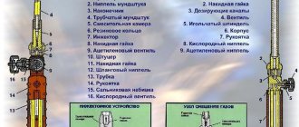
Features of gas burners
Gas welding of steels is a process that requires the use of a variety of devices. Gas burners are an integral element of equipment used in various industries. The design of the products is approximately the same: each burner consists of a housing. Several elements are attached to it at once: a tip, a valve that regulates the fuel supply, and a lever that regulates the height of the flame. The connection to the cylinder is made by a reducer, while the burner itself can often be supplemented with piezo ignition, flame wind protection and other components.
A propane-based gas torch for welding is safe to operate, providing a high flame temperature: it is sufficient to perform a range of jobs. Many types of welding are carried out using acetylene torches, which operate on a mixture of acetylene and oxygen.
Materials suitable for gas welding
Photo of the device of torches for gas welding
Gas welding is indispensable in industry, construction, and agriculture. It allows you to fasten a large number of metals.
Welding cast iron is necessary to eliminate defects, cracks, and broken parts of the product. The gas burner should have a small flame to avoid graininess of the weld seam.
Soldering bronze involves the use of a reduction flame. The work uses wire identical to the material being welded.
Copper processing does not require a gap between the edges. This is due to the fluidity of the material, which can complicate the gas welding process.
Carbon steels can be joined using different welding methods. The seams are made coarse by using low carbon steel wire.
Types of gas cutters
Gas cutters come in different types: acetylene, propane, and operating on gas substitutes or liquid fuel. The design of the products includes a handle, nipples to which gas hoses are attached, a body, an injector, a mixing chamber, a tube, a gas cutter head and a tube with a valve. Gas welding of metals and its quality depend on how well the cutter is selected.
The essence of its work is as follows: oxygen flows from the cylinder into the reducer, sleeve, and then enters the body - here the cutter branches into two channels. Some of the oxygen passes through the valve and is directed to the injector. From here the gas comes out at high speed, and during this process flammable gas is sucked in. When combined with oxygen, it forms a flammable mixture, which is directed into the space between the mouthpieces and burns. As a result, a heating flame appears. Oxygen, which was directed through the second channel, exits into the tube, due to which a cutting jet is formed. It is he who processes the metal section.
Types of welding flame
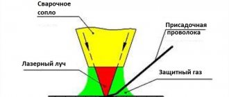
A welding flame is formed as a result of the combustion of flammable gases or vapors of flammable liquids mixed with technical oxygen. In this case, the flame has a complex structure and structure, which is shown in the figure below. The quality of gas welding largely depends on the correct adjustment of the flame, which the welder sets “by eye” in shape and color. Therefore, it is very important to know the structure and structure of a gas burner flame in order to take this into account in everyday work. The shape, color and structure of the burner flame are changed by the ratio of acetylene and oxygen supplied to the combustion zone. As an example, consider the structure of an acetylene-oxygen flame.
Components of acetylene-oxygen flame: 1-core; 2-recovery zone; 3-torch flame
The flame core has the shape of a cylinder with a pointed end, around which there is a brightly luminous shell. The length of the flame core is regulated by the supply rate of the gas mixture and its qualitative composition. The diameter of the core depends on the size of the mouthpiece and the flow rate of the combustible mixture.
The structure of the flame changes when the mixture ratio changes and can be: normal, carbonized and oxidizing.
Normal (recovery) type of welding flame
A normal flame is produced when one volume of oxygen is supplied to one volume of combustible gas. If acetylene is used as a flammable gas, then the process of its normal combustion can be written in the following form: C2H2+ O2 = 2CO+ H2.
In this case, the products of incomplete combustion burn out due to the oxygen present in the atmospheric air. Since there are no absolutely pure substances in nature and oxygen contains a certain amount of impurities, a normal flame is obtained at a certain increased value, that is, at a ratio of acetylene and oxygen equal to 1.1 -1.2. The core of a normal flame is light with a slightly darkened reduction zone and torch. The shape of the flame core resembles a cylinder with clear outlines and a rounded end. The diameter of the core depends on the size of the welding torch mouthpiece, and the length is determined by the rate of release of the gas mixture. Around the flame core there is a light shell in which the combustion of hot carbon particles occurs. At a high gas supply rate, the flame promotes the combustion of the metal and blows it out of the weld pool.
The reduction zone of the gas flame is darker in color and is located in the space within 20 mm from the end of the core. The flame temperature in this zone can reach 3150°C (during the combustion of acetylene). The size of the reduction zone depends on the number of the welding nozzle. Using this flame zone, the metal is heated, melted and welded. The rest of the flame, located behind the reduction zone, consisting of carbon dioxide, water vapor and nitrogen, has a significantly lower temperature.
Carburizing view of welding flame
A carburized flame is produced when the ratio of acetylene to oxygen exceeds the specified ratio, that is, it becomes greater than the value of 1.1. Theoretically, a carburized flame is obtained when 0.95 volumes of oxygen or less are supplied to the burner. In this case, the flame core increases in volume and loses its outline. The lack of oxygen in such a flame leads to incomplete combustion, and it begins to smoke. Excess acetylene in a carburized flame causes it to decompose into carbon and hydrogen. Carbon from the flame passes into the metal, carburizing it. Typically, a carburized flame is used for welding aluminum and surfacing hard alloys.
The reduction zone of a carburized flame is light and practically merges with the core. The temperature of such a flame is lower, so it is more difficult to work with it. To return the flame to a normal state, increase the supply of oxygen or reduce the supply of acetylene.
Oxidative type of welding flame
An oxidizing flame occurs when there is a lack of acetylene, that is, the acetylene:oxygen ratio becomes less than 1.1. A practically oxidizing flame is obtained when the volume of oxygen exceeds the volume of acetylene by 1.3. The core of such a flame shortens and sharpens, and its edges become blurred and the color fades. The temperature of such a flame is higher than the normal temperature. Excess oxygen oxidizes iron and impurities found in steel, which ultimately leads to brittleness of the weld, porosity of its structure, depleted in manganese and silicon. Therefore, when welding steels with an oxidizing flame, filler wire with a high content of these elements, which are deoxidizing agents, is used. The highest normal flame temperature is achieved in the reducing zone.
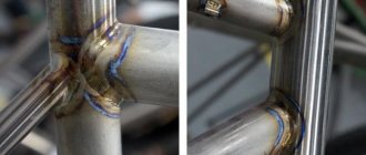
Features of pipe welding
Welding of gas pipes is carried out in several stages. First, the metal is prepared, that is, markings are carried out, pipes are cut and assembled. Due to the round cross-section of the pipes, cutting is performed with a thermal cutter. Most of the welding work involves assembling parts for it, when it is necessary to take into account many details - from the series of products to their diameter and other factors. Assembly is performed using welding tacks, which prevent possible displacement of pipe sections, which affects the appearance of cracks during cooling.
The arc is lit. This is done in different ways. Then the melting of metals - base and electrode - begins. For a quality seam, it is important to pay attention to the angle of inclination of the electrode.
Advantages and disadvantages
Cooking using the gas method is not difficult, but it, like electric arc, semi-automatic or argon welding, has its advantages and disadvantages.
Advantages of gas connection:
- This is an ideal way to weld copper, brass and cast iron;
- materials with different levels of melting can be processed due to the high temperature generated as a result of combustion;
- you can cook anywhere, since no special equipment or electrical outlet is required;
- when using high-quality additional wire and a correctly selected flame, high-quality and beautiful seams are obtained (widely used for connecting components in pipelines);
- the work product heats up slowly, which avoids deformation or loss, as is the case with semi-automatic welding or when using an electrode).
In addition to the positive aspects, the essence of gas welding also has several disadvantages:
- the heating zone is quite wide, that is, not only the seam zone is heated, but also a large area around it. This may damage the product;
- inability to work with parts whose thickness exceeds 5 mm;
- It is highly not recommended to perform gas-flame overlapping welding, this will lead to deformation of the fusion site;
- high operational hazard, since gases form a chemical mixture that tends to ignite.
Safety precautions
Gas welding is a process that requires careful attention. Dangerous situations can arise in several cases:
- Welding should not be carried out near flammable and flammable materials (gasoline, kerosene, tow, shavings).
- If welding is performed in a confined space, workers should periodically go out into fresh air.
- Work must be carried out in well-ventilated areas.
- If gas-flame processing of metal is carried out, the room must be ventilated to remove harmful gases.
- Cutting and welding are carried out at a distance of up to 10 m from bypass ramps and acetylene generators.
- Loading box sections should not overfill with carbide.
- The generator housing must always be filled with the required amount of water.
- It is forbidden to work with an oxygen cylinder whose pressure is below normal.
- The burner flame is directed in the direction opposite to the gas supply source.
Welding work must be carried out with maximum compliance with safety rules and using only high-quality equipment. This will make the process safe and the metal connection reliable.
Impact of steel impurities
The impact of steel impurities on the continuity of the gas cutting process directly depends on their percentage:
- Aluminum. The acceptable level is 0.5%.
- Copper. An impurity content of up to 0.7% of the total mass does not affect the process.
- Vanadium, phosphorus, sulfur. They do not have a negative effect at acceptable values.
- Tungsten. Does not interfere with cutting continuity up to 10%. A higher percentage makes the work difficult, at 20% the process is interrupted.
- Molybdenum. Allowed content is 0.25%.
- Nickel. The upper limit is 7-8%.
- Chromium. Maximum – 4-5% negative impact. An increased level sharply worsens cutting conditions. Requires the use of flux.
- Silicon. With standard indicators it does not interfere with the process. At 4% cutting is not possible.
- Carbon. Indicators range from 0.4% (norm) to 1-1.25% (work stoppage).
- Manganese. Standard – up to 0.4%. As it increases, cutting becomes more difficult; when it reaches 14%, it becomes impossible.