grooved wheel to support movement and change the direction of the tensioned cable
This article is about the mechanical concept and design. For other uses, see Pulley (disambiguation).
| Pulley | |
| Pulleys on a ship. In this context, pulleys are usually called blocks. | |
| Classification | Simple machine |
| Industry | Construction, transport |
| Wheels | 1 |
| Axles | 1 |
And the pulley
This is a wheel on an axle or a shaft that is designed to support the movement and change the direction of a tensioned cable or belt or transmit power between the shaft and the cable or belt. In the case of a pulley supported by a frame or shell which does not transmit power to the shaft but is used to guide the cable or apply force, the supporting shell is called a block and the pulley may be called a sheave.
A pulley may have a groove or grooves between the flanges around its circumference to find a cable or belt. The drive element of a pulley system can be a rope, cable, belt, or chain.
The earliest evidence of the use of pulleys dates back to Ancient Egypt in the Twelfth Dynasty (1991-1802 BC)[1] and Mesopotamia in the early 2nd millennium BC. e.[2] In Roman Egypt, Hero of Alexandria (c. 10-70 AD) identified the pulley as one of six simple machines used for lifting weights.[3] The pulleys are assembled in a locking and catching manner in order to provide a mechanical advantage to apply large forces. Pulleys are also assembled as part of belt and chain drives to transmit power from one rotating shaft to another.[4][5] The Life of Plutarch recounts a scene in which Archimedes proved the effectiveness of compound pulleys and the locking and catching system by using one to pull a fully loaded ship toward him as if it were gliding through water. [6]
Block and grab
Various ways to rig the tackle.[7]
A set of pulleys assembled so that they rotate independently on the same axis form a block. Two pulleys with a rope attached to one of the pulleys and threaded through two sets of pulleys form a block and catch.[8][9]
And the block and catch is assembled in such a way that one block is attached to a fixed attachment point and the other to a moving load. In an ideal situation, the mechanical advantage of the pulley and tackle is equal to the number of pieces of rope supporting the moving pulley.
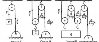
The diagram on the right shows the ideal mechanical advantage of each of the blocks and tackle units.[7] the following is shown:
- Tackle: 2
- Tackle: 3
- Double selection: 4
- Equipment for gynecology: 5
- Triple buy: 6
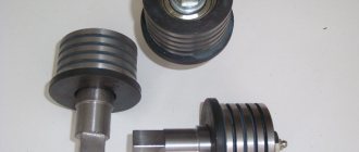
Types of pulleys for V-belts
Depending on the design, pulleys of types 1...6 (Fig. 1...6) and types 7...9 (Fig. 7...9) are distinguished.
Type 1 pulley is a monolithic pulley with a one-sided protruding hub.
Pulley type 2 is monolithic with a one-sided groove.
Type 3 pulley is monolithic with a one-sided groove and a protruding hub.
Type 4 pulley - with a disk and a hub protruding from one end of the rim.
Type 5 pulley - with a disk and a hub shortened at one end of the rim.
Type 6 pulley - with a disk and a hub protruding from one end and shortened from the other end of the rim.
Type 7 pulley - with spokes and a hub protruding from one end of the rim.
Type 8 pulley - with spokes and a hub shortened at one end of the rim.
Type 9 pulley - with spokes and a hub protruding from one end and shortened from the other end of the rim.
The mounting hole design options are given (Fig. 10):
- cylindrical,
- conical with key,
- conical.
Fig.10
Rope and pulley systems
Oil Rig Pulley A hoist using a composite pulley system offers the advantage of 4. A single fixed pulley is installed on the hoist (device).
Two movable pulleys (connected together) are attached to the hook. One end of the cable is attached to the crane frame, the other to the winch. A rope and pulley system, i.e. block and catch, is characterized by the use of a single continuous rope to transmit tensile force around one or more pulleys to lift or move a load - the rope may be a light rope or a strong rope. This system is included in the list of simple machines identified by Renaissance scientists.[10][11]
If a rope and pulley system does not dissipate or store energy, its mechanical advantage is the number of rope parts acting on the load. This can be shown as follows.
Consider a set of pulleys that form a movable pulley and the pieces of rope that support that pulley. If there is n
these parts of the rope supporting the load
W,
then the balance of forces on the moving block shows that the tension in each of the parts of the rope should be
F/p.
This means that the input force on the rope is
T
=
W/p.
Thus, the block and tackle reduce the applied force by a factor.
P.
- The gun rig has one pulley in both the fixed and movable units with two cable parts supporting the load. W.
- The separation of the pulleys in the gripper shows the balance of forces, which results in a tension in the rope of W/2.
- The double gripper has two pulleys in both a fixed and a moving unit with four cable sections supporting the load. W.
- The separation of the pulleys in a double gripper shows the balance of forces that results in a W/4 rope tension.
Working method
The simplest theory of how a pulley system works assumes that the pulleys and slings are weightless and that there is no energy loss due to friction. It is also assumed that the lines do not stretch.
In equilibrium, the forces on the moving block must be zero. In addition, the tension of the rope should be the same for each of its parts. This means that each of the two parts of the rope supporting the moving block must support half the load.
- Fixed pulley
- Diagram 1: Load F
on a movable pulley is balanced by the tension of the two parts of the rope supporting the pulley.
- Movable pulley
- Diagram 2: Movable pulley lifting a load W
supported by two cable parts with tension
W/2.
These are different types of pulley systems:
- Fixed:
A
fixed
pulley has an axle mounted in bearings attached to a supporting structure. A fixed pulley changes the direction of force on a rope or belt moving around its circumference. Mechanical advantage is achieved by combining a fixed pulley with a movable pulley or another fixed pulley of a different diameter. - Movable:
A
movable
pulley has an axle in a movable block. One movable pulley is supported by two parts of the same cable and has a mechanical advantage of two. - Complex:
The combination of fixed and movable pulleys forms blocking and catching.
And blocking and catching
can have several pulleys installed on a fixed and movable axle, which further increases the mechanical advantage.
- Diagram 3: The "advantage-seeking" gun rig has a rope attached to a moving pulley. The rope tension is W / 3
giving an advantage of three.
- Diagram 3a: The Luff rig adds a fixed pulley at a "disadvantage". The rope tension remains W / 3
giving an advantage of three.
The mechanical advantage of a gun rig can be increased by interchanging the fixed and movable pulleys so that the cable is attached to the movable pulley and the cable is pulled in the direction of the lifted load. In this case, blocking and catching is said to be “seeking to gain.”[12] Diagram 3 shows that the load is now supported by three parts of the rope. W
which means the tension in the rope
is W/3
. So the mechanical advantage is three.
By adding a pulley to a stationary boom block, the direction of the pulling force is reversed, although the mechanical advantage remains the same, Diagram 3a. This is an example of a Luff rig.
Free body diagrams
The mechanical advantage of a pulley system can be analyzed using a free body diagram which balances the tension force in the rope with the gravitational force on the load. In an ideal system, frictionless, massless pulleys dissipate no energy and allow changes in cable direction without stretching or fraying. In this case, the balance of forces on the free body, including the load, W
, and
n
support sections of the rope with tension
T
, gives:
n T − W = 0. { displaystyle nT-W = 0.}
The ratio of load to input tension force is a mechanical advantage. M.A.
pulley systems, [13]
M A = W T = p.
{ displaystyle MA = { frac {W} {T)) = n.} Thus, the mechanical advantage of the system is equal to the number of rope sections carrying the load.
Accuracy standards for the manufacture of pulleys
The standard also gives accuracy standards for the manufacture of pulleys:
- permissible deviation from the nominal value of the calculated diameter of the pulleys - according to h11;
- maximum deviations of the groove angle of pulleys processed by cutting should be no more than: ±1° - pulleys for belts of sections Z, A.B;
- ±30′ - pulleys for belts of sections C, D, E, EO.
The runout tolerance of the conical working surface of the pulley groove in a given direction for every 100 mm of the design diameter relative to the axis should be no more than:
- 0.20 mm - at a pulley rotation speed of up to 8 s -1;
- 0.15 mm - at a pulley rotation speed of over 8 s -1 to 16 s -1 ;
- 0.10 mm - at a pulley rotation speed above 16 s -1.
The Ra parameter value of the roughness of the working surfaces of the pulley grooves should be no more than 2.5 microns.
Belt and pulley systems
Flat belt on a belt pulley Belt and pulley Tapered pulley top driven linear shaft
A belt and pulley system consists of two or more pulleys common to the belt. This allows mechanical force, torque, and speed to be transmitted along the axes. If the pulleys have different diameters, a mechanical advantage is achieved.
A belt drive is similar to a belt drive. chain drive; however, the belt pulley may be smooth (without individual locking elements, as on a chain sprocket, spur gear, or toothed belt), so that the mechanical advantage is approximately determined by the pitch ratio of the pulleys, rather than being fixed exactly by the tooth ratio, as is the case with gears and sprockets .
In the case of a drum pulley, without a groove or flanges, the pulley is often slightly convex to keep the belt flat and centered. Sometimes it is referred to as a pulley with a crown. Although linear shafts were once widely used in the factory, this type of pulley is still used to rotate the rotating brush in a vertical position. vacuum cleaners, belt sanders and band saws.[14] Farm tractors until the early 1950s usually had a flat belt pulley (which is what a belt pulley is
the magazine was named after). It has been replaced by other mechanisms with greater flexibility in methods of use, such as power take-off and hydraulics.
Just as gear diameters (and therefore their number of teeth) determine the gear ratio and thus speed increases or decreases, the mechanical advantage of pulley diameters determines the same factors. and stepped pulleys (which operate on the same principle, although the names tend to apply to the flat belt and V-belt versions, respectively) are a way of providing multiple ratios in a belt and pulley system that can be switched as needed. necessary, just like the gearbox provides this function with a gear train that can be shifted. Stepped V-belt pulleys are the most common way for drilling machines to supply the spindle over a range of speeds.
Pulley groove profile for V-belt
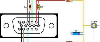
Legend:
Wp is the design width of the pulley groove;
b is the groove depth above the design width;
dp—design pulley diameter;
h is the groove depth below the design width;
e is the distance between the axes of the grooves;
f is the distance between the axes of the outer groove and the nearest end of the pulley;
de is the outer diameter of the pulley;
r is the radius of curvature of the upper edge of the pulley groove;
Recommendations
| Wikimedia Commons has media related to Pulleys . |
- Arnold, Dieter (1991). Building in Egypt: Pharaonic Masonry
. Oxford University Press. paragraph 71. ISBN 9780195113747. - Muri, Peter Roger Stewart (1999). Ancient Mesopotamian Materials and Industries: Archaeological Evidence
. Eisenbrauns. n.. ISBN 9781575060422. - Asher, Abbott Payson (1988). History of Mechanical Inventions
. USA: Courier Dover Publications. paragraph 98. ISBN 0-486-25593-X. - Uiker, John; Pennock, Gordon; Shigley, Joseph (2010). Theory of machines and mechanisms
(4th ed.). Oxford University Press, USA. ISBN 978-0-19-537123-9. - Paul, Burton (1979). Kinematics and dynamics of planar machines
(illustrated ed.). Prentice Hall. ISBN 978-0-13-516062-6. - Rorres, Chris (2017). Archimedes in the 21st century
. Published by Springer International. paragraph 71. ISBN 9783319580593. - ^ a b
McDonald, Joseph A. (14 June 2008).
Tooling Handbook: For Construction and Industrial Plants
. McGraw-Hill Professional. item 376. ISBN 978-0-07-149301-7. - Prater, Edward L. (1994). "Basic Machines" (PDF). Center for Naval Education and Training Professional Development and Technology, NAVEDTRA 14037.
- Bureau of Naval Personnel (1971) [1965]. Basic machines and how they work
(PDF). Dover Publications. ISBN 0-486-21709-4. Archived from the original (PDF) on 09/22/2016. Retrieved 2011-12-13. - Avery, Elroy (1878). Elementary Physics
. Sheldon and company. item 459. wheel and axle. - Bowser, Edward (1890). An Elementary Treatise on Analytical Mechanics: With Numerous Examples
(5th ed.). D. Van Nostrand Company. paragraph 180. - "Handbook of Marine Engineering, Chapter 5, General Rigging" (PDF). scchead apartments.com.
- Tiner, J. H. Exploring the World of Physics: From Simple Machines to Nuclear Energy
. Master Books (May 1, 2006) p. 68. - "How Crown Pulleys Hold a Flat Belt." Wood Gears.
Nominal design diameters dp of pulleys, mm:
50; (53); 56; (60); 63; (67); 71; (75); 80; (85); 90; (95); 100; (106); 112; (118); 125; (132); 140; (150); 160; (170); 180; (190); 200; (212); 224; (236); 250; (265); 280; (300); 315; (335); 355; (375); 400; (425); 450; 475; 500; (530); 560; (600); (620); 630; (670); 710; (750); 800; (850); 900; (950); 1000; (1060); 1120; (1180); 1250; (1320); 1400; (1500); 1600; (1700); 1800; (1900); 2000; (2120); 2240; (2360); 2500; (2650); (2800); (3000); (3150); (3550); (3750); (4000) mm.
Note. The dimensions indicated in brackets are used in technically justified cases.
Encyclopedia of technology
a wheel with the help of which the rotation of one shaft is transmitted to another shaft (with the same wheel) by means of a closed belt or rope stretched over the rims of the wheels. The surface of the pulley rim is cylindrical, can be smooth (sometimes with protrusions along the edge of the rim to protect the belt from running away) for a flat belt or with grooves for a round or V-belt (trapezoidal cross-section). Pulleys are made from cast iron, steel, light alloys, plastic, and sometimes wood. It is used in belt and rope drives in drives of agricultural machines, electric generators in cars, textile machines, lifting devices (for example, in elevators), tape recorders, etc.
ACCEPTANCE
3.1. Pulleys must be subject to acceptance and periodic tests by the manufacturer.
3.2. Acceptance tests for compliance with the requirements of clause 2.13; 2.14; 2.16; 2.17; 2.19; 2.21; 2.22; 2.24 each pulley is subjected.
3.3. 10% of the pulleys from the batch are subjected to periodic testing. The batch must consist of pulleys of the same symbol, presented according to one document. Periodic tests are carried out to ensure compliance with all technical requirements established in the standard, twice a year.
3.4. If during periodic testing at least one of the parameters does not meet the requirements of this standard, re-test the double number of pulleys in full. The results of repeated tests are final.
Damper or solid pulleys?
In practice, it has been proven that it is quite simple to neutralize engine vibrations using a torsional vibration damper. Such dampers are widely used in diesel cars, while they are not so common in gasoline cars (usually in trucks and buses). On passenger cars, the crankshaft pulley is usually all-metal, which is its Achilles heel - vibrations freely transmitted from the engine lead to rapid wear of the pulley, as a result of which it does not reach the 10 years of operation guaranteed by the manufacturer. The advantages of the damper pulley are:
- Engine noise is reduced;
- The amplitude of torsional vibrations is reduced by 2-5 times - this increases the survivability of the pulley and adjacent units (only the damper wears out quickly);
- Shock loads are effectively absorbed;
- Increases fuel efficiency and environmental friendliness of the vehicle.
Contrary to the assurances of some car enthusiasts, the damper cannot seriously reduce the load on the belt. However, a pulley with a damping insert has several more significant disadvantages:
- It is more expensive than an all-metal pulley;
- The damper becomes unusable over time (the rubber insert cracks or breaks).
Despite the disadvantages, damper pulleys perform better than non-damper pulleys. One of their problems is the need for preventative replacement. As soon as the rubber element cracks, the entire pulley ceases to perform its main tasks
Please note: modern fuel efficient engines are manufactured to fit damper pulleys only.
And let’s immediately touch on another question: what is a lightweight pulley? This is the name given to a part made of aluminum alloy. Usually it has a damping element, but exceptions sometimes occur. For example, in the USA, the alloys from which some automobile engine parts are made are called alloys for aviation applications. They are durable, resistant to temperature changes and very lightweight. Aluminum pulleys introduce peculiarities into the operation of the engine (it slows down faster after the driver releases the gas pedal) and copes worse with vibrations (solved by installing a damper).
Second dismantling method
There is another tricky way to unscrew the crankshaft pulley. It is done independently without the presence of an assistant. Having previously removed the generator drive belt, put a head or a spanner on the bolt of the mechanism, the handle of which rests on some surface.
You should not rest it against the body or other parts of the engine compartment. When unscrewing, the key can damage units with rubber pipes, scratch and even damage the body. In the future it will become clear why. It is best to rest the key handle on the ground or floor, placing a wooden board under it. The main thing is that there is a hard and smooth surface. If the key does not reach the stop, then by moving the head or rotating the crankshaft, rest it against a hard surface.
Now, turning on the ignition, you need to crank the engine with the starter. Its force is more than enough to break the pulley fixing bolt. The main thing is not to overdo it and properly rest the key so that it stands firmly in place and does not wobble. Even a slight displacement will cause it to jump off the bolt head and damage the engine compartment. Under no circumstances should you start the engine, and if you do manage to do so, turn it off immediately.
To prevent the engine from starting, you can remove the fuel supply hose from the fuel pump to the carburetor if it is a carburetor engine, or the hose entering the fuel rail if the engine is injection.
Notes
- Pulley // Encyclopedic Dictionary of Brockhaus and Efron: in 86 volumes (82 volumes and 4 additional). - St. Petersburg, 1890-1907.
- . .
- . internet-law.ru
. - . www.gosthelp.ru
. - . www.internet-law.ru
. - . .
- ↑ V.I.Anuryev.
Handbook of mechanical engineering designer. In 3 volumes. Volume 2. - M: Mechanical Engineering, 2001. - P. 709. - 912 p. — ISBN 5-217-02964-1. - ↑ . Drawing
. - IN AND.
Anuriev. Handbook of mechanical engineering designer. In 3 volumes. Volume 2.. - M: Mechanical Engineering, 2001. - P. 724. - 912 p. — ISBN 5-217-02964-1. - ↑ V.I.Anuryev.
Handbook of mechanical engineering designer. In 3 volumes. Volume 2.. - M: Mechanical Engineering, 2001. - P. 735. - 912 p. — ISBN 5-217-02964-1. - . edu74.uu.ru
. - (unavailable link). Hardware and fasteners
. Retrieved January 9, 2022. - . www.baltech.ru
.
Basic faults
Belt adjustment and dimensions
For the Neva MB-2 walk-behind tractor, the A-1180 drive belt is used. This model uses one belt that provides forward movement.
In other modifications of the Neva MB-2 model, two drive belts are used. Reverse gearing occurs in the gearbox itself.
Replacing the belt for MB-2 walk-behind tractors is carried out in the following sequence:
- The shield is removed, and then the pulley protective cover.
- The spring from the walk-behind tractor rod is removed to loosen the belt.
- The screws securing the bracket are turned.
- The bracket rotates to a position in which the limiting pins do not prevent the part from being removed from the pulley.
- The pulleys are adjusted, and then a new belt is installed.
- Pull the belt onto the gear shaft pulley, and then onto the motor pulley.
- In reverse order, place the remaining parts in their places.
Replacement of gearbox seals
The oil seals in the Neva MB-2 walk-behind tractor are replaced if an oil leak is detected. This condition is dangerous because the walk-behind tractor gearbox may be left without oil, and this will lead to rapid wear of the unit.
The sequence for replacing oil seals is as follows:
- Remove the cutters from the shaft, cleaning the shaft and covers from dirt and oil residues.
- Unscrew the cover bolts, tap off the oil and debris, and remove the cover from the gearbox.
- The old oil seal is replaced with a new one and wiped dry.
- The cover is returned to its place (if necessary, it is placed on sealant) and fixed with bolts.
Adjusting and tuning the Neva MB-2 carburetor
The functionality and durability of the walk-behind tractor engine depend on the stable operation of the carburetor.
This is why its adjustment and tuning are so important. In addition, if the carburetor is incorrectly configured, a gasoline walk-behind tractor may experience increased fuel consumption
The carburetor of the Neva MB-2 walk-behind tractor is adjusted as follows:
- The full throttle and idle screw are turned to the limit.
- Both screws are unscrewed 1-1.5 turns.
- Next comes starting and warming up the engine.
- The throttle control lever is placed in a position in which the engine will operate at minimum speed.
- Set the minimum idle speed until the unit operates stable.
- The idle speed is set to maximum.
- The minimum idle speed is adjusted.
- Steps 6 and 7 are performed until the engine runs smoothly (more smoothly by ear) at idle speed.
For long-term and uninterrupted operation of the walk-behind tractor, it is necessary to regularly perform engine diagnostics, monitor the frequency of oil changes, and also comply with operating conditions and time intervals for scheduled maintenance.
Adjustment of valves
Adjusting the valves is a fairly simple procedure that requires wrenches, screwdrivers and a feeler gauge. The valve adjustment process is needed to establish optimal and technically correct clearances between the valves of a walk-behind tractor engine. Adjusting valves using the example of the Neva MB-23 walk-behind tractor (the principle is the same for everyone)