Grinding pulleys for band saws
Causes of breakdowns
When sawing a log with a band saw, the cut must be smooth. If there is a wave and cracks on the saw, then there are several factors:
- under-rolled saw
- the saw is dull
- incorrect sharpening along the side edge
- pulley profile wear
Reasons for vibration:
- eccentricity of saw pulleys
- play or wear in the bearing units of the band sawmill
- loose bolts
- incorrectly installed racks
- wear on the surface of the saw pulleys and drive belts of the band sawmill
As the surface of the saw pulleys wears out, it is necessary to sharpen them periodically. Saw pulleys must undergo static and dynamic balancing during manufacture. The pulleys must be aligned in the same vertical plane and on the same horizontal plane.
Causes of cracks on a band saw:
- improper sharpening of the sinus
- incorrect rolling
- pulley profile development
- bearing wear
- pulley runout
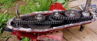
We can eliminate this by grinding the profile without removing the pulleys from the machine, and also train the sharpener to edit and roll band saws. After 5000-8000 hours of operation of the band saw machine, wear occurs on the leading edge pulleys. Accordingly, the convexity of the pulley profile increases. It follows from this that the middle of the saw is tensioned on the pulley, but the edges of the saw are not tensioned. As a result, when sawing waves, the saw cuts unstably, productivity is lost, the volume of sawn products, quality, and useful yield decrease.
Types of pulleys
Flat pulley
Flat pulley
Convex pulley
Convex center 1/3 of pulley width
Convex pulley
Center the convex at the center of the width of the pulley
We can repair your pulleys on site without removing them from the machine.
Services
Starting and setting up machines
Launching and setting up band saw machines. Preparing sharpening tools for work.
Grinding pulleys according to profile
Setting up, alignment, bombing, grooving. Flat, convex and with convexity 1/3 of the profile width
Training of specialists
Sharpening, rolling, straightening when working with band, frame and circular saws.
?
Staff consultations
For purchasing sharpening machines and preparing sharpening tools for working at temperatures down to -50ºС
List of work for repairing a band saw machine:
- machine diagnostics
- pulley wear measurement
- runout measurement
- axial runout measurement
- pulley profile inspection
- grinding of pulleys according to the profile specified by the manufacturer
- grinding the ends of the pulley
- elimination of runout (if necessary)
- alignment and adjustment of pulleys
- control cut
- selection of sawmill and sharpening equipment
- consultation on choosing wood cutting tools
- inspection and adjustment of sharpening equipment
- consulting the grinding department staff (straightening, rolling, stelliting, welding seams, cracks, sharpening along the tooth profile and tooth geometry along the front, back and side edges)
- in order to establish stable and high-quality sawing, increase sawing, and useful yield.
Personnel must be trained in band saw preparation and in the proper operation of the band saw.
- All
- American machine
- MEBOR and RULMAK machines
- TANAKA machine
Band saw consultations
- experienced specialists will answer all your questions regarding band saws and machines
- help with setting up sharpening machines
- training of personnel in rolling and preparation of the band blade (from welding the seam to starting the saw)
- clarification of the correct sharpening and formation of profiles of the cutting elements of saw teeth
- tips for choosing a tool
We carry out all work at the client’s enterprise, throughout Russia
Work on flat and profile pulleys
We have experience working with such sawmills as:
Mebor HTZ 1000-1200, Tanaka, Primultini and other German, Turkish, Finnish and Japanese sawmills. Over the course of 15 years, I had to grind a large number of different pulleys with diameters from 1000 to 1500 mm. Twenty years of experience in preparing a complete set of sharpening tools for sawmilling. We provide training for sharpeners on band, circular and frame saws.
DIY band sawmill
The pulleys were “borrowed” from a combine harvester similar to the “Neva”, the diameter of the pulleys is 30-32 cm. I ground them so that the belt I put on protruded a little (a couple of millimeters), later I removed the belts and cut them without them, much quieter and better. There is very little turning work. This is due to the fact that I mainly used a half-inch pipe and a pipe (I don’t know which one) for the guides, but it clearly fits half an inch (the gap is 1-2mm, which is even convenient for welding). Let's start with the "rails"
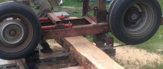
The rail itself is a 50mm corner, installed side up (then the wheels must be installed very well, otherwise the wheel will wear off the corner), usually they make it with the edge of the corner up, then the wheel will not wear off. The “sleepers” are 25*25mm profile pipes. Also welded in the form of sleepers, between the profile tubes, is the above-mentioned (more precisely mentioned below) half-inch pipe, onto which the log fasteners (claws) are placed. The fasteners move and tilt freely, the wood is clamped by hitting the clamps with a hammer, as a result of which the clamp self-jams.
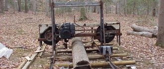
Profile tubes protrude beyond the rails; adjusting bolts (M14*100mm) are installed on these protrusions. “Bridges” are installed on the profile tubes on which the log is laid. The last two have a distance of 50 cm between them (for short workpieces). Photos 1, 2. View of the sawmill. Photos 3, 4, 5. The pulley housings (hub from Moskvich) are welded (with periodic cutting and re-welding, this is how I aligned the pulleys, more on that later) to the tubes, and everything moves together along horizontal guide tubes (half-inch pipe) and can be fixed with bolts.
The right (driven) pulley is automatically tensioned by a spring (from the shock absorber from the KaSika motorcycle). The left (leading) one is fixed, but can be moved when changing the size of the band saw. In photo 8, the engine belt tensioning mechanism is slightly visible. Pulley left-right. Photos 9, 10 When developing the videos, I started from the fact that they should be hardened. I made the entire sawmill in my garage, the only pulleys I took to the turner to grind (they didn’t fit into my machine), so I was looking for the simplest and most reliable method. As a result, I made a “roller unit” from a set of bearings, two (I think 202) are identical and the rear one is a little larger (+2-4mm). Rice. 1, photos 11, 12 “Rollers” on a machined shaft designed so that, if necessary, washers can be installed between the bearings (when changing the width of the saw). The shaft is inserted into the same pair of tubes (half-inch + “female”), with a half-inch shaft welded with the axes offset ( blue line in the figure) everything is attached to the guide tubes so that the roller assembly is adjusted in height (not necessarily, but a home-made saw is desirable) and moves to the sides with subsequent fixation (to set the width of the opening depending on the diameter of the log). A dropper for coolant is installed on the roller mounted on the side of the driven pulley. The “cutting block” moves along the channels using hairpin screws; for rigid installation of the “cutting block”, bolts with a lock nut are installed. The lifting mechanism is visible in the photos. More about installing pulleys.
“According to the book,” they should hit parallel. I made them at an angle (2-4 degrees), so that the tape would be “pulled back” by the rollers, otherwise it would fly off. I cut with a reserve for shrinkage and deformation during drying, the run-up is 3.5 m in length with a normal saw and sawing does not exceed 1-1.5 mm.
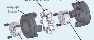
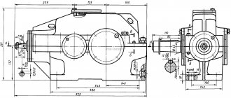
What gear motors are installed on disc sawmills?
In the woodworking industry and sawmills, disc sawmills are widely used for cutting wood. The efficiency and performance of the device depends on the gear motor mounted on the frame.
The purpose of this device is to start the mechanism and regulate the torque of the drive shaft. This is necessary for smooth and stable movement of the circular saw when cutting logs. The absence of a gearbox on the motor will result in the shaft rotating at the same speed and the operator will not be able to increase or decrease the torque. The device is mounted on the saw frame at the factory, so workers do not need to install or configure anything when they arrive at the sawmill. It is enough to externally inspect the fastenings and the body.
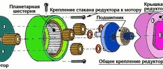
Gear type and number of stages
Designed to change the speed at which the shaft rotates, gearmotors are divided into multiplier and multiplier. The type depends on the needs at a particular site. If you need to increase it, then install multiplier type models. To reduce it, it is recommended to use the second option.
In practice, devices with a gear worm gear are most often installed. There is also a combined transmission for performing certain tasks. The number of stages is 1, 2 and 3 depending on the model, purpose and power of the device.
Industrial sawmills use gearboxes that have several stages. This is necessary to ensure the required characteristics and torque. For a small or homemade sawmill, a single-stage mechanism is suitable. There are various types, differing in size, weight, additional functions and operating conditions.
Type of gears
The design of the circular sawmill can be equipped with gear motors with different gear shapes. The choice is determined by the design and purpose. Gears used:
- conical;
- cylindrical;
- conical-cylindrical.
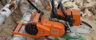
The placement of the shaft has two options: vertical or horizontal, which depends on the design features of the particular model and the tasks performed.
Both types of models are common in workshops and enterprises. Even at the same sawmill you can see products with shafts installed differently. They operate from a three-phase network. Starting on one phase is carried out using an automatic starter assembled on capacitors.
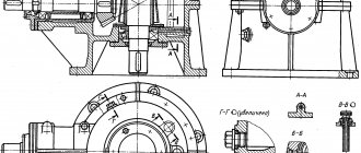
Service
During operation, gears and gears wear out the fastest. The reason may be the appearance of play or insufficient lubrication. At enterprises, craftsmen must monitor the condition of the shaft, fastening and housing.
Periodically you need to check the oil level and tighten the fastening nuts. If cracks appear in the housing, it must be replaced. The service life of the unit is at least 5 years without major repairs.
Adjusting guide rollers on a band sawmill
Adjusting the guide rollers, or dampers as they are also called, is one of the important operations on band sawmills. In addition, the final size of the material, as well as the quality of processing of the entire material, will depend on the correct adjustment of the rollers.
First of all, let's look at the guide roller itself. Its components and possible malfunctions, as well as methods for eliminating them.
Guide roller
The roller consists of several parts. These are, of course, the roller itself, bearings, usually two of them, retaining rings and an intermediate ring or washer. The bearings themselves come in different brands depending on the type of sawmill. Also, a washer is installed between them to allow lubricant to pass through. All this is fixed together with the bearings inside the roller with stoppers. For which there are special slots inside the roller.
Then the roller with bearings is pressed onto the shaft and fixed to the shaft with a bolt or nut. Also, the shafts can be simple, straight. Or they can be shifted to the side; they are also called eccentrics. If a simple shaft is adjusted with pins up and down. Then the eccentrics are adjusted simply by turning the shaft.
First of all, the roller has a round shape of varying diameters. At the same time, there is a curb on the back side to prevent the saw blade from coming off. Also, on the surface of the roller there are slots for ejecting sawdust. In addition, it is necessary to take into account that during operation, mandatory cleaning of these slots gives a good result.
Installation and adjustment of guide rollers
Installation
First of all, before installing and adjusting the guide rollers, you need to check how worn the roller parts are.
Firstly, is there any beating of the roller, just shake the roller to determine this. In case of even the slightest runout, the bearings or shaft are replaced. There may also be wear on the inside of the roller.
Secondly, the surface of the roller must be even in width. Because during operation it wears out like a cone, which greatly affects the quality of the material. Also in diameter, the roller should not be an ellipse.
After assembling the guide roller and checking it, we begin installing it on the machine. We insert the shaft into the roller holder and secure it with a special bolt. In the event that the holders are on heels. Therefore, it is fixed with several bolts if it is an eccentric.
Adjustment
For further adjustment, place the saw band and apply a slight tension so that the band is pressed against the rollers. Loosen the bolts securing the roller shaft and move the roller so that the distance from the front of the roller to the base of the belt tooth is 3-5 millimeters, and fix the roller shaft again.
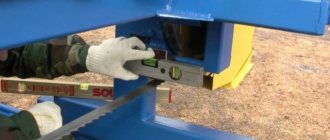
Then we set a level, which should be at least 120 cm, on the bottom of the frame and measure from the drive wheels to the level, and then from the guide rollers to the level. The rollers should be 3-5 mm below the drive wheels.
Using studs, we set this distance, unscrewing or tightening with nuts. On the eccentrics, loosen the fixing bolts and turn the shaft to set the required size and fix the roller shaft again.
Next, we fully tension the saw blade according to the instructions; the tension of the tape should be minimal, but sufficient for work. We take a small level and place it across the belt between the rollers, while paying attention to the protruding teeth of the tape, the level should not stand on them, and using studs or bolts, we level the tape to a level state, moving the level from one roller to another.
After all these manipulations, we roll the sawmill to the first support post and set the size. It will be easier to do this if you first set the size, for example, 10 cm between the tape and the guide post, remember that you need to measure from the teeth protruding downwards, and then simply unscrew the fastenings of the ruler on the frame and set the size on the ruler.
We check all our adjustments, making control measurements, as well as the reliability of fixing the rollers, and make a control cut of the log; if the cut showed the quality and dimensional accuracy of the material, then all adjustments of the guide rollers were made correctly. In the future, all that remains is to maintain these adjustments, promptly eliminating malfunctions of the roller parts.