A bevel gearbox is an independent mechanism that, using couplings or open gears, is connected to an electric motor and a working machine. It is made in the form of a unit designed to transmit power from the engine to other working mechanisms. The drive circuit may also include both open gears and belt or chain drives mounted on shafts that rest on bearings in housing housings. The main purpose of the device is to increase the torque of the driven shaft while simultaneously reducing the angular velocity.
Design No. 2
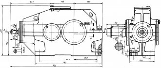
bevel gearbox with horizontal high-speed and vertical low-speed shafts . A special feature of the gearbox design is the lubrication and bearing protection system. The gear is lubricated by dipping the gear in oil. The drive shaft bearings are lubricated separately and each bearing has a double-sided oil-retaining device. The lower bearing assembly is protected from liquid oil getting into it by two cups, fixedly fixed: one on the housing, and the other on the wheel. The glass, mounted on the wheel, has the shape of a cone expanding at the bottom, which ensures that the oil is thrown away from the shaft during rotation.
Description
A gearbox (bevel) is a mechanism that converts a high angular speed of rotation of the input shaft into a low one on the output shaft. In this case, the torque on the output shaft increases in proportion to the decrease in rotation speed.
The gearbox (bevel) consists of a housing in which gears, shafts, shaft bearings, their lubrication systems, etc. are located. The presence of the housing ensures safety, good lubrication and, therefore, high efficiency, in comparison, for example, with open gears.
Main characteristics of gearboxes
Main characteristics of gearboxes: gear ratio, rotation speed of input and output shafts, gear ratio, transmitted power, number of stages and type of gears.
Design No. 3
The gearbox is a single-stage bevel gearbox with angles between the shaft axes not equal to 90º . The gearbox has limited use. When the load capacity of the engagement is high and the high-speed shaft rotates at a significant speed, the design of the bearing unit, version II, is used. Roller bearings with short cylindrical rollers carry radial load, and a radial ball bearing installed in a cup with a gap carries axial load.
In the bearing unit of version III, tapered bearings are installed “extended”. When assembling a bevel gear, the bearings are first adjusted by axial movement of the inner bearing ring using a round nut, and then the engagement by moving the gear shaft in the axial direction by changing the thickness of a set of thin metal spacers between the housing and the cup flange.
Advantages
Angular bevel gearboxes have a number of advantages:
- compact dimensions;
- high efficiency (up to 98);
- operational reliability and stability under high, uneven loads;
- undemanding;
- resistance to overheating even with intensive use.
Single-stage bevel gearboxes, which are affordable, have some disadvantages along with their advantages. The gear shaft has a high probability of failure during startup. To prevent high-power gearboxes, they are equipped with soft start devices. If it is necessary to increase the gear ratio with an increase in torque, a two-stage unit is used, consisting of coaxial cylindrical and conical parts. Such gearboxes have their own advantages:
- high performance;
- excellent abrasion resistance;
- long period of uninterrupted operation;
- relatively compact dimensions;
- relatively silent operation;
- ease of maintenance and installation;
- moderate cost.
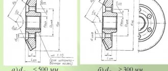
High-speed shaft versions for bevel gearboxes.
Designs of the high-speed shaft of a bevel gearbox for the case of application between an electric motor and a belt or chain drive gearbox are shown in Fig. 1…4.
Rice. 1, 3, 4 - the gear shaft and pulley (sprocket) bearings are separate. The pulley (star) rests on the glass through its two bearings. The shaft is unloaded from the belt tension forces, the torque from the pulley (sprocket) is transmitted either through an elastic coupling and splines (Fig. 3), or through a rigid compensating clutch (Fig. 1), or through splines (Fig. 4).
Rice. 2 - the pulley is located directly on the shaft and loads it with forces from the belt tension.
Related Pages
- Kinematic diagrams of gearboxes
- Gearbox with vertical shafts
- Gearbox with two high-speed shafts.
- Two-stage gearbox
- Two-stage coaxial gearbox
- Design options for shaft supports of a cylindrical two-stage coaxial gearbox
- Gearbox with torsion shafts
- Two-stage, three-flow coaxial gearbox
- Coaxial cylindrical gearbox with internal gearing of low-speed stage
- Geared motor MTs2S-125
- Cylindrical gearbox Ts2-160
- Two-stage cylindrical gearbox 1Ts2U.
- Gearbox Ts2-200.
- Special gearbox
- Gearbox Ts3KF-100
- Reducer RTC-500.
- Three-stage gearbox
- Reducer RCT-1015.
- Bevel gearbox K-125.
- Bevel-helical gearbox
- Worm gearbox.
- Helical worm gear motor.
- Helical-worm gearbox.
- Two-stage worm gearbox.
Scope of application
This type of gearbox is used when it is necessary to transmit high torque at an angle of 90 degrees. Such units are suitable for intensive long-term operation; they are capable of trouble-free operation in situations of uneven loads, high speeds, and also in conditions where the system is often activated and stopped.
Bevel gearboxes can be successfully used in many applications, including:
- for various equipment in the agricultural sector;
- for equipment in the engineering industry;
- for tools and mixing equipment in construction;
- for equipment in the food industry;
- for many other types of production activities and performing household tasks.
Gearboxes with bevel gears are installed on production lines, where there is a need to change the direction of the forces developed by the torques of the mechanisms. They are often found on conveyor lines, machine tools, and lift mechanisms, which are subject to particularly stringent requirements.
Operating principle of the gas reducer
Based on the type of design, devices are divided into two main types - direct and reverse. Without delving into the intricacies of the design, we can say that the operation of the gas reducer is aimed at reducing the output pressure to the required value using a system of membranes, springs and valves. For compressed gases, reducers are designed for an input pressure of up to 250 atmospheres, for liquefied gases - up to 25 atmospheres. At the outlet, balloon reducers regulate pressure in the range of 1-25 atmospheres. Control of inlet and outlet pressure is carried out using independent built-in pressure gauges (1 or 2).
Story
The process of the industrial revolution was marked by the transition of wooden parts to metal ones. Wind- and water-powered propulsors already created forces that were difficult for wooden parts to withstand. The main factor of the industrial revolution was the creation of more advanced mechanisms and the search for new energy resources. The advent of the steam engine required very large capacities. Consequently, there was a need to design metal gearboxes. By the mid-nineteenth century, handlooms had already begun to fade into the background and be replaced by mechanical ones with three times the productivity.
Energy became cheaper, which led to increased speed of machine tools and strengthened their economic advantage. The steam engine was powerful enough to run several textile machines. The machines were placed around the steam engine to increase efficiency. The steam engine freed up production capabilities, which made it possible to build enterprises both near water and in places where there was coal, transport, labor and markets. New times have selected optimal gear designs.
It was those that had the highest economic effect that gained the most popularity. The mid-19th century was marked by the appearance of the first serial gearboxes. Well, the appearance a few years later of internal combustion engines and electric drives marked the creation of gearboxes with specified parameters. Gear mechanisms transmitted rotational movements from high-speed engines and transformed their parameters. Even the earliest examples of electric motors and internal combustion were endowed with too much speed and torque, which, a priori, was not suitable for use in industry. Today, of course, it is difficult to find any vehicle or technological equipment that is devoid of a gear mechanism. Gearboxes are used in almost all vehicles and technological equipment. As you already understand, gear drives have gone through many years of development.
Advantages and disadvantages
The design of bevel gearboxes is similar to cylindrical gearboxes, so their advantages and disadvantages are similar. The main advantage of a bevel gearbox is the arrangement of gears or couplings at an angle. This makes it possible to transmit rotation from the drive shaft to the driven shaft, located at an angle of 90 degrees to the first.
Another important advantage of such a device is its immunity to variable and short-term loads. For this reason, they are often used in production processes with frequent starts.
As mentioned above, bevel gearboxes have a structure similar to cylindrical gearboxes, but they have their own disadvantages. These include:
- lower efficiency;
- Wheel seizures occur more frequently.
Despite the fact that the efficiency of such a unit is 10% lower and cases of gear jamming are possible, bevel gearboxes are in great demand and have found application in many areas.
What does a gearbox do?
The word reducer itself literally means reduction. Accordingly, editors were invented in order to reduce the rotation speed. At the same time, the gearbox increases the torque power. As we already said at the beginning of the article, gearboxes are used in cars. There they are needed in order to carry out downshifts and returns. This principle can be clearly seen in the example of the operation of bicycle gears, where the role of a gearbox is performed by the so-called sprockets. Note that today gearboxes are used not only in cars, but also in many engines, as well as to reduce and maintain the pressure of the working environment, including gas, steam and liquid.
Cylindrical units
The most common options. They serve in all areas of industrial production; the advantage of this type is its simplicity, and the absence of the need for cooling, since there is nothing to heat up there.
This class also has a very high efficiency - up to 98%! A certain AK-47 in the world of machine structures.
The ability to withstand heavy loads removes restrictions in the areas of their use. They are used both in metal-cutting machines and in mixers and grinders.
Gearbox service life
The service life of the gearbox depends on correct calculations of the operating load parameters. Also, timely preventative maintenance of the gearbox, changing oil and seals also affects the duration of operation. Regular preventive inspection will allow you to avoid unplanned repairs or replacement of the gearbox. The oil level is monitored through an inspection window in the gearbox and, if necessary, topped up to the required level.
Below is a table of the dependence of the gearbox service life on the transmission type:
| Gearbox type | Guaranteed resource in hours |
| Cylindrical, planetary, conical, cylindrical-conical | more than 25000 |
| Wave, worm, globoid | more than 10000 |
1.Classification of gearboxes
Reducer for general machine-building purposes. This type of equipment is an independent unit used in machine drives. Its technical characteristics meet common requirements for different applications. Structurally, general machine-building gearboxes may differ.
Special gearboxes are designed for automotive, aviation and other highly specialized industries. From the name it is clear that the units of this group must correspond to the specifics and parameters of a particular application.
Gearboxes can be classified according to the following criteria:
- By type of gear and number of stages;
- According to the location of the axes of the input/output shafts in space and relative to each other;
- According to the method of fastening.
Wave transmissions
The emergence and further development of wave transmission took place back in 1959. The inventor, as well as the person who patented this technology, was the American engineer Masser.
The wave gearbox consists of several main elements:
- A fixed wheel with internal teeth.
- A rotating wheel with external teeth.
- Driven.
Among the advantages that can be identified from this method of transmitting motion are lower weight and size of the device, higher accuracy from a kinematic point of view, as well as less backlash. If necessary, this type of motion transmission can be used in a sealed space without using sealing seals. This indicator is most important for such equipment as aviation, space, and underwater. In addition, the wave gearbox is also used in some machines used in the chemical industry.