The essence of the parameter
The essence of gear ratios is the ratio of the frequency (speed) of rotation of the input shaft and the low-speed one (at the output). To simplify, we can say this: the characteristic determines the number of full revolutions that the input shaft must make while the low-speed one makes 1 revolution.
This characteristic is indicated in the designations of the mechanisms. Example for a model with a worm gear: Ch-100-50. Here the indicator we are interested in is listed last and means that while the output shaft makes 1 revolution, its high-speed “colleague” manages to “wind up” 50 circles.
Technical characteristics of the gearbox
In order to choose the right gearbox for use as part of a drive, you need to know its main parameters:
- gearbox type;
- main parameter;
- gear ratio;
- rotation frequency;
- torque;
- radial load;
- efficiency;
- resource;
- noise level;
- execution option.
Let's look at these parameters in more detail.
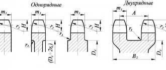
The type of gearbox depends on the type of transmission used. The main types of transmission stages are cylindrical, worm, conical, planetary or wave. The gearbox can consist of one, two or more stages of the same type. Gearboxes that combine different types of stages are also used, for example, cylindrical worm or planetary worm gear. There are several other types of gears, such as worm-globoid, spiroid, lantern and others. But they are a further development of the basic types of gears already indicated. The choice of gearbox depends on its purpose, restrictions on weight, torque, dimensions, and layout of drive elements. The main parameter is the geometric characteristic, which determines the weight, size and power parameters. Depends on the type of gearbox and is determined in accordance with GOST 31592-2012. In a helical gearbox, this is the distance between the axes of the low-speed and adjacent stages (Fig. 1 - dimension AwT);
- in worm gear – the distance between the axes of the worm and the wheel;
- in planetary – half the diameter of the carrier;
- in conical - the pitch diameter of the larger of the wheels;
- in a wave gearbox - the internal diameter of the flexible disk.
Gear ratio - shows how many times the torque and rotation speed on the low-speed (output) shaft of the gearbox changes compared to the input shaft. Dimensionless quantity. This is a key parameter of the gearbox operation, equal to the product of all gear ratios of its stages. The more there are, the greater the overall gear ratio will be.
The table shows the standard indicators of gear ratios for one degree of different types:
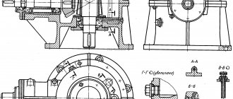
By increasing the number of stages, such as in a 3-stage helical gearbox or combining different types - planetary-cylindrical, you can obtain a gearbox ratio of several thousand units. Rated torque – expressed in N*m and regulates the amount of maximum applied force on the shaft at which the gearbox can perform its functions. The operating parameters of the gearbox are indicated in the passport or operating manual. Radial load is a force that can be absorbed by the end section of a low-speed or high-speed shaft, arising from attached structural elements, such as a belt drive or coupling. If you do not exceed this load, the gearbox will also work without breakdowns for the entire prescribed period. Rotation frequency - shows the number of revolutions that the gearbox shaft makes per minute. Indicated for both low-speed (output) and high-speed (input) shafts. It is also not recommended to exceed this parameter, because wear of the working surfaces of the steps and bearings will occur much faster. Coefficient of efficiency (efficiency) , a dimensionless quantity, is determined by the ratio of energy expended to useful work, i.e. power received at the output shaft. In modern gearboxes, depending on the type of gearbox, the efficiency varies from 0.4 to 0.99. The most productive are cylindrical, bevel, planetary, the least productive are worm and wave gearboxes, due to the design features. Resource – measured in hours and shows how long the gearbox is capable of operating in certified mode until a certain level of wear. Passport mode is a limitation on loads, speed, type of oil used and its temperature. The onset of wear does not mean that the gearbox is out of order, but further operation can lead to unexpected breakdowns and costly repairs. Also, to ensure service life, it is necessary to carry out timely maintenance of the gearbox. Some manufacturers indicate service life in years under a certain load mode instead of a resource. Noise characteristics - the maximum noise level created by the gearbox at nominal operating mode, exceeding which is not permissible, measured in decibels (dB). Gearbox design is a short numerical designation indicating the main design features, such as: shaft arrangement (coaxial, parallel, perpendicular), housing design and mounting positions. The figure shows various housing options - on feet (a), with a flange (b), with a hollow input shaft (c). In case “a” the load will be supplied through a belt drive or coupling, in case “b” the gearbox shaft is centered with the actuator hole and secured with a flange, in case “c” the gearbox is “mounted” on the actuator shaft and attached to the housing through reaction rod - a lever that prevents the gearbox from turning on the shaft.
The installation design can also be different - from above, from the side, from the front, from the back. This is shown more clearly in the figure:
Climatic design - this parameter is required not only for gearboxes, but in general for any industrial equipment or product. Shows in what climatic conditions (temperature, humidity, precipitation, etc.) operation is permissible, determined by GOST 15150-69. In conclusion, here is an example of a gearbox designation:
Definition
There are concepts of actual and nominal gear ratios of the gearbox. These values are close, but may still differ:
- the actual value is established during testing (the actual maximum accurate rotation speed of the elements), can include any number of decimal places;
- nominal - rounded actual received (7.75 = 8).
This division helped to standardize the designations and simplify the selection of gearboxes for various operating conditions.
Table 1. Examples of rounding
You can find out what gear ratio the gearbox produces in one of 3 ways.
- Look at the body. As a rule, there is an engraving, plate or sticker that lists the characteristics of the model.
- Read in the device passport or on the manufacturer’s website.
- Calculate yourself.
Gear modules
| 0,25 | (0,7) | (1,75) | 3 | (5,5) | 10 | (18) | 32 |
| 0,3 | 0,8; (0,9) | 2 | (3,5) | 6 | (11) | 20 | (36) |
| 0,4 | 1; (1,125) | (2,25) | 4 | (7) | 12 | (22) | 40 |
| 0,5 | 1,25 | 2,5 | (4,5) | 8 | (14) | 25 | (45) |
| 0,6 | 1,5 | (2,75) | 5 | (9) | 16 | (28) | 50 |
It is allowed to use modules 3.25; 3.75 and 4.25 mm for the automotive industry and 6.5 mm module for the tractor industry Applies to spur, bevel and spur gear modules. For cylindrical wheels with oblique and chevron teeth, the module is determined by the normal pitch. In exceptional justified cases, it is allowed to determine the module in the end section. For bevel gears, the module is determined by the larger diameter. For worm wheels with a cylindrical worm, the module is determined in the axial section of the worm. It is not recommended to use module values enclosed in brackets
Formula
The simplest way to calculate the gear ratio is using the following formula:
I = N1 / N2
- I is the required value, rotation ratio;
- N1 - revolutions per 1 minute made by the input shaft;
- N2 is the rotation speed of the working element at the output.
The result obtained using this gear ratio formula is rounded to the nearest value indicated in the technical description of the series.
Range of gear ratios for different types of gearboxes
| Gearbox type | Gear ratios |
| Worm single stage | 8-80 |
| Worm two-stage | 25-10000 |
| Cylindrical single stage | 2-6,3 |
| Cylindrical two-stage | 8-50 |
| Cylindrical three stage | 31,5-200 |
| Conical-cylindrical single stage | 6,3-28 |
| Conical-cylindrical two-stage | 28-180 |
Areas of application for gearboxes
Gearboxes are used in cases where it is necessary to change the angular velocity of rotation transmitted from the drive in the working mechanism, as well as in cases where it is necessary to increase torque. Depending on the specifics of the equipment where the use of this mechanism is required, different types of gearboxes are used. The geared motor is installed on construction and earth-moving equipment, used in cement factories, and used in machines in the mining and oil refining industries and in other areas.
A worm gearbox is indispensable in mechanisms that require smooth movement. This device is used in elevators, construction equipment and pumps. During operation, the desired increase in torque is achieved without creating unnecessary noise during the movement of working units.
The helical gearbox is the most common and is used in almost all areas of industrial activity, including mechanical engineering, robotics and construction. The reason for this popularity is the high efficiency of the mechanism and its cost-effectiveness during operation and maintenance.
Bevel gearboxes are used in mechanical engineering in drives, as well as in machine tools. The most convenient mechanism is for placement in rotary mechanisms, where it is necessary to place the drive and driven shafts perpendicularly.
Equipment selection
This must be understood: even in devices of identical configuration/design, the ratio of the rotation speed of the input shaft and the output shaft may differ. To make the right choice, it is important to know how to calculate the gear ratio of a gear motor. Although there is another way - check the data directly with the manufacturer.
Production engineers know everything about the characteristics of gear equipment and are happy to help the customer select a mechanism that optimally meets the needs of the production site. Professional calculations and comprehensive information support are provided free of charge. Experts will tell you how to determine the gear ratio and place an order. They will also help you calculate the cost and guide you on the delivery time.
Main parameters of cylindrical gears
The standard applies to cylindrical external gears for gearboxes and accelerators, including combined ones (bevel-cylindrical, cylindrical-worm, etc.), made as independent units. The standard does not apply to gearboxes of special purpose and special design gearboxes. For built-in gearboxes, the standard is recommended
Center distances
| 1 row | 40 | 50 | 63 | 80 | 100 | 125 | — | 160 | — | 200 | — | 250 | — | 315 | — | 400 |
| 2nd row | — | — | — | — | — | — | 140 | — | 180 | — | 225 | — | 280 | — | 355 | — |
| 1 row | — | 500 | — | 630 | — | 800 | — | 1000 | — | 1250 | — | 1600 | — | 2000 | — | 2500 |
| 2nd row | 450 | — | 560 | — | 710 | — | 900 | — | 1120 | — | 1400 | — | 1800 | — | 2240 | — |
1st row should be preferred to 2nd
Selection and calculation of gear motor
Purchasing a motor gearbox is an investment in technical and technological business processes, which must not only be justified, but also pay off. And the payback largely depends on the choice of gear motor for specific purposes. It is carried out on the basis of a professional calculation of power, dimensions, productive efficiency, and the required load level for specific purposes of use.
To avoid mistakes that can lead to early wear of the equipment and costly financial losses, the calculation of the geared motor should be carried out by qualified specialists. If necessary, experts can conduct this and other studies to select a gearbox.
Examples of our helical gearboxes
Bevel gearbox, single-stage, air-cooled
Documentation:
Technical and service documentation, test report (without load), manufacturer's confirming certificates will be provided to you free of charge.
Quality certificates:
There are quality certificates and type approvals for the products of the following organizations and societies: GL / DNV / ABS / RS / CCS / LRS / GOST R
Painting and preservation:
Factory standard paint. Preservation of external exposed parts and gear elements with Tectyl 506. Internal components with Tectyl 511.
Our company offers to buy bevel gearboxes from a reliable manufacturer.
- Bevel gearbox
- Kegelradgetrieben
- Reductores de engranajes conicos
Please send your requests for equipment to the technical department of our company by e-mail, tel. +7 (495) 225 57 86.
Central website of the company ENCE GmbH Our service company Intech GmbH
Head Offices in the CIS countries:
Russia Kazakhstan Ukraine Turkmenistan Uzbekistan Latvia Lithuania
Advantages and disadvantages
The design of bevel gearboxes is similar to cylindrical gearboxes, so their advantages and disadvantages are similar. The main advantage of a bevel gearbox is the arrangement of gears or couplings at an angle. This makes it possible to transmit rotation from the drive shaft to the driven shaft, located at an angle of 90 degrees to the first.
Another important advantage of such a device is its immunity to variable and short-term loads. For this reason, they are often used in production processes with frequent starts.
As mentioned above, bevel gearboxes have a structure similar to cylindrical gearboxes, but they have their own disadvantages. These include:
Despite the fact that the efficiency of such a unit is 10% lower and cases of gear jamming are possible, bevel gearboxes are in great demand and have found application in many areas.
Wheel reducer maintenance
To increase the reliability of the unit and extend the period of its safe operation, it is necessary to carry out its technical inspection and appropriate maintenance at certain intervals, using special monitoring and measuring equipment. Before starting repair work, you must first disconnect the gearbox from the clutch housing, under which, however, like under the front axle, movable stands are installed. A fixed type stand is placed under the gearbox. Next, you should turn off the hydraulic system and disconnect the tractor frame, roll it out and disconnect the half-frame from the clutch housing. After disassembly is completed, you can proceed to diagnosing the unit, first of all paying attention to the following points:
- Indicators of oil level in the hydraulic tank;
- Is the engine operating at full power?
- What condition is the chassis in?
- Is there an oil leak?
- Is there pressure in the drain line of the hydraulic motor and at its inlet;
- What is the condition of the fastening joints?
- Are the roller bearings in good condition?
- Does the gear clutch system on the upper and lower bevel pairs need to be replaced?
If, during the inspection of the wheel gearbox, a significant decrease in the oil level in the upper bevel pair is detected, then this is a sure sign that there is a leak in the system. It is imperative to identify the causes of its occurrence and eliminate the malfunction as quickly as possible. It is quite possible that this may even require partial disassembly of this unit, although, in fact, this is the only way to fix the problem.
Power
During rotational movements of the working parts of the mechanisms, resistance arises, which leads to friction - abrasion of the units. With the right choice of gearbox in terms of power, it is able to overcome this resistance. Therefore, this point is of great importance when you need to buy a gearmotor for long-term purposes.
The power itself - P - is calculated as a quotient of the force and speed of the gearbox. The formula looks like this:
To select the desired gearmotor, it is necessary to compare the power data at the input and output - P1 and P2, respectively. output power of the geared motor
At the output, the power of the gearbox (P1 > P2) should be lower than at the input. The norm of this inequality is explained by the inevitable losses in performance during engagement as a result of friction between parts.
When calculating capacity, it is imperative to use accurate data: due to different efficiency indicators, the probability of selection error when using approximate data is close to 80%.