Homemade gearboxes, gearboxes, etc.
I propose to collect homemade gearboxes, gearboxes, drive axles and the like in one place.
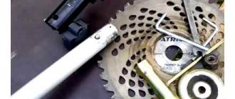
Discuss methods for manufacturing parts and housings for them. TO THE EDITOR - if there is already a similar topic - please tell me. here is my bevel gear. gears from the differential from the gear, the axle gear was tucked under the 25 mm shaft and the bushing was welded, the pinion gear was simply welded to the 20 mm shaft, everything else can be seen from the photographs, if you ask for a photo of cutting the splines post-on, I just wanted to show how I cut it with alignment, I didn’t bother
Remember: it’s better to lose a day, then fly to my channel in five minutes https://www.youtube.com/channel/UC1vTkviCAeiA9Z4yTOHM7uQ
Finally the Internet is working. I assembled it 2 years ago to connect the GAZ-51 gearbox and the M-412 bridge. The body is channel 14, gears are from the 51st gearbox (3rd gear, splines are welded into the drive gearbox for the output shaft of the GAZ-51 gearbox), and at the output of the gearbox there is a cut-off secondary shaft of the GAZ-51 gearbox.
Built a boring head.
I'll try to bore it for a homemade transfer case.
Built a boring head.
and what is the cutter itself made of? I thought for a long time about what I could make a reduction gear out of, and today it dawned on me, I found the crown of the launcher and the bendex starter, the gear ratio should be about 7.5 and the chain drive 2.3 in total 17.25, maybe it will be useful for someone, for example, for making a meat grinder.
Remember: it’s better to lose a day, then fly to my channel in five minutes https://www.youtube.com/channel/UC1vTkviCAeiA9Z4yTOHM7uQ
and what is the cutter itself made of?
A sharpened tap. Today I tried to sharpen it a little - it takes cleanly, now I just have time to choose a free time.
A cutter made from a tap is for small holes (up to 30 mm), for “larger” ones – soldered.
I put the transfer case aside for now - I don’t have much time, I’m making the same gearbox as before. The GAZ gears couldn’t withstand the uprooting of cherries in the fall. These should withstand it (the gearbox is from KPI, it feeds the mass into the chopper).
The computer did not send photos and then refused to turn on. It can’t work from the phone either. I'll try to install the gearbox tomorrow.
Not in order, but you can understand.
The gearbox is assembled, tested and working. Now a reverse gearbox suggests itself. If anyone has done this, tell me which gears it is made of.
The topic has died down, probably no one is interested in it. Winter has passed, but there was not enough time for the gearbox, now we have to hurry. In general terms: I used gears from the gearbox - Gas 52 and the oil pump drive gear from engine A - 41, the drive shaft from the primary ZAZ gearbox and the secondary gearbox Gas 52, housing - sheet 10 mm. Photo of preliminary assembly, the body is not finished yet.
The topic has died down, probably no one is interested in it. Z
Why isn’t it interesting, very much so, but I don’t understand where the reverse is?
I made one for myself, later I’ll make another one, but this time with access to the front, and I need to think about something with the reverse
The topic has died down, probably no one is interested in it. Z
Why isn’t it interesting, very much so, but I don’t understand where the reverse is?
The drive gear moves on splines, connecting to the driven gear directly or through a gap (double).
Explain, I don’t know how you set the diameter for the bearing on the head?
Explain, I don’t know how you set the diameter for the bearing on the head?
First I go through with a small drill (5-10 mm), then a few mm less than the required diameter (I couldn’t find more than 50 mm, so it took me a long time to bore to the required 80), and after the drill, 0.25 - 0.5 mm per pass with measurement after each pass. The head is homemade, it “plays” a little, you have to play it safe.
after the drill 0.25 - 0.5 mm per pass
Can I have a drawing (schematic) of the head, I’m interested in the cutter feed mechanism itself
, I’m interested in the cutter feed mechanism itself
so he even has a video here, a regular drilling machine and a cutter with an offset
I'm interested in the cutting mechanism itself
Yes, everything is quite primitive, the thread is m8x1, loosened the dovetail clamp, turned the screw, for example, 1/4 turn - the hole diameter changed by 0.5 mm. The accuracy is not high, but it is enough to seat the bearing.
thread m8x1, loosened the dovetail clamp, turned the screw, for example, 1/4 turn - the hole diameter changed by 0.5 mm.
wow primitive! I can't do this.
We also need a gearbox, from the engine to the clutch. The gears from the ZID gearbox (2nd gear) and the gear from the guitar lathe to the parasite came in handy. Still in the process.
Here is the result. The reduction is 2.91, the input is from the engine crankshaft through the “donut” from the VAZ, the output is the ZAZ flywheel.
Noting in this thread .. I’m also thinking about a gearbox .. a little history: having installed a diesel engine on a Zila, the speed of 60-65 at 2300 rpm was not enough. so that's what I'm getting at. I have thoughts about making a divider like on a Kamaz and putting it in front of a Zilov gearbox. train of thought: take the input shaft from the ZiL high-speed gearbox (there are such... but a large gap between 3rd and 4th gear is very difficult for the engine). I repeat: the input shaft is the secondary shaft from the same gearbox. an intermediate shaft with a constant mesh gear (high-speed) and a 5th gear driven and driven (the gear ratio is 0.85, I don’t remember exactly) using the method of welding, etc., connect the secondary shaft of my gearbox with the primary shaft of the original ZIL gearbox and hide it all in a 20mm metal housing, trick up the fork included and get something like this. https://www.sychaolida.com/upload/201301/1357828666.jpg
All-terrain vehicle "Esaul": farm, final drives and Krazovsky "bast shoes"
Despite climate change and the conquest of nature, there are still many places in Russia that require very special equipment to reach. The spurs of the eastern Sayan Mountains in the Irkutsk region, where Alexander Pobelyansky lives, are one of these corners. There is some kind of fabulous combination of different off-road coatings here. Steep descents and ascents either slip deep ruts from the “goose” under the wheels, or treacherous quicksand. You also have to climb over scattered rocks, sometimes stepping over bare rocks - just like in American rock crawling. There are swamps, and winter is generous with snow. Well-prepared jeeps are not far away and are somehow carried literally by hand. Tracked vehicles go a little further, but in terms of off-road qualities they are not universal and not ideal. Something different is needed.
Alexander Pobelyansky, 45 years old, specialized secondary education (driver). In 1988, together with his brother and father, he began creating various off-road equipment. Only 16 examples of all-terrain vehicles with low-pressure pneumatics were built. He also built snowmobiles. For a long time he was the head of the technical design circle at the Regional Center for Children's Technical Creativity. One of his students entered the University. Bauman
Who remembers, on Soviet television there was such a program “You Can Do It,” which inspired many to create homemade all-terrain vehicles. So Alexander, together with his brother and father, was inspired by the idea of designing units whose characteristics would exceed the factory ones. They built, as was customary then, on low-pressure pneumatics, simply put, on chambers. Three-wheeled, four-wheeled, of course, floating and, of course, perfectly at home in swamps and snow, they did not meet one condition - they were in no way adapted for mountain conditions. After all, even for branded low-pressure tires, with tread and thicker than conventional tubes, the organic habitat is the flat terrain of the tundra or the Arctic. And for the mountains you also need a suspension with good articulation, locking, high torque with a decent transmission reduction. And it is desirable that all this could move on weak-bearing soils without losing the ability.
The first embodiment of the new concept was the Vepr. Jeep, pickup, truck? A symbiosis built in 1998 on the basis of components and assemblies from GAZ-53, GAZ-66 and ZIL-157. Built for specific wheels! Alexander chose the tires for which KrAZ was nicknamed “laptezhniki”. Large contact patch, 1200 mm outer diameter and almost 150 kg assembled weight. Perhaps, it was the lightening of the “rubber” (by cutting off layers) and the creation of original discs that perform the functions of bad-locks that became the most important task. The mass was reduced to 123 kg, the edge of the disks maintains a pressure of 0.2 atmospheres. On such “bast shoes” you can walk on top, and cling to stones with your own cut tread, and not be afraid of cuts and punctures.
“Vepr” was created on a shortened frame from “half a hundred and three.” The gearbox without synchronizers and the gasoline V8 also came from him. “Razdatka”, as well as gearboxes (rear with self-locking cross-axle differential) - GAZ-66. But the beams are from other models. The front is ZIL-157, the rear is GAZ-51. The reason is that the frontal area of their gearbox housings is significantly smaller than that of the same 66th. In ruts this is fundamental. Stockings of both bridges and axle shafts were added to obtain the desired track
Now “Vepr” is already a veteran. But, practically not seeing at least some roads out of its almost 150 thousand kilometers, it still remained in service. Mushrooms, berries, a pine cone, pulling a truck with firewood out of the taiga, taking repairmen to power lines - it’s all his job. In a word, “Vepr” remained for the farm. The fulfillment of the dream - the assault on the Sayan foothills - passed the baton to the next project of Alexander Pobelyansky, “Esaulu”.
And what, in fact, did not suit you in “Vepr”? The disadvantages of pavement on spring structures are well known - limited wheel travel. In addition, the tipping angle did not quite correspond to the operating conditions. And the all-terrain vehicle turned out to be heavy - 2700 kg of “equipment”.
"Esaul" was built according to a different design. True, even in all its nuances it was not born immediately; so to speak, it was polished as it passed off-road tests. For example, in its first configuration the machine had a single-level tubular frame and a Luazov engine. Now, instead of the usual flat structure, the basis of the “Esaul” is a truss, and the engine is already on its third, this time an injection one from a Chevy Niva. However, here we need to understand in detail.
The chassis of the future “Esaul” still has a single-level tubular frame, a Luaz engine and transmission. But, of course, with wheel gears
Yes, it was the space frame, similar to that used in motorsports, that became the foundation of the all-terrain vehicle. Why not an ordinary ladder type from some factory? With a height of 250 mm, Pobelyansky’s original design made it possible to hide all transmission units inside. This eliminates their contact with the surface and somewhat reduces the center of gravity. In addition, the truss turned out to be light (about 100 kg) and durable - according to calculations in the center, it is capable of supporting a load of up to seven tons.
The spatial “backbone” of “Esaul” is not just a load-bearing structure. In essence, it plays the role of natural protection for all transmission units that are located inside it
Suspension - two A-arms connected to the frame hubs and cross members. Their freedom is practically unlimited, for which ball joints taken from the KamAZ tie rod are responsible. The natural limiters are shock absorbers from the Gazelle and Nivov springs, and they are secured by metal bands. Now the circuit is set to approximately 650 mm of travel, but this is not the limit.
The basis of the suspension is closed A-shaped or triangular levers. They are connected at two ends to wheel reducers, at the top there is a ball joint from the KAMAZ transverse traction
The transmission, like the frame, has also undergone changes since the first trips. But only for two units. Replacing the Luaz engine with the Togliatti one led to the corresponding choice of gearbox and transfer case - they are from Shniva. The remaining nodes remained the same. These are the main pairs from the Lutsk jeep - the rear ones, since they have forced locking. And homemade final drives based on gears from KamAZ and the TT-4 tractor in original housings. The latter, contrary to established ideas, are not intended to increase the already considerable ground clearance of 500 mm, but to unload the Luaz pairs, which, of course, would not be able to rotate the wheels “alone” for about twenty meters. Oh yes, to combine the direction of rotation of the LuAZ gearboxes and the VAZ gearbox between the gearbox and the gearbox, Alexander mounted a homemade gear block.
Wheel gearboxes, of course, with external gear engagement. This made it possible to obtain the appropriate vertical layout of the all-terrain vehicle (suspension/frame, wheel diameter, body height) and obtain a gear ratio of 3.33:1. Although the main task of the on-board vehicles, of course, is to relieve the rest of the transmission components and multiply the torque arriving at the wheels
Luaz gearboxes were chosen for a number of reasons. Of those working as part of independent suspensions, that is, not being parts of bridges, they are perhaps the most affordable. The gear ratios of the main pairs are quite good. And, as you know, the rear cross-axle differential is forcibly locked. That's why he's standing in front. The brake drums (also LuAZ) are moved towards the gearboxes so that the brake pipes pass through the frame. Working cylinders - Zhiguli
Previously, there were Luaz parts here, now the shock absorbers and springs are from the Gazelle and Niva, respectively. Selected based on their length
Drive shafts are front shortened cardan shafts from UAZ. Only one was hurt, and only once.
The parking brake, as Alexander calls it, is a band brake. Two half-rings with friction linings on the inside use rods to compress the flange onto the propeller shaft. Adjustment provided. And the main advantage is that in winter it’s easy to clear it of ice.
Previously there was a steering gearbox from a GAZ-53, now there is a Zilov one, which is more powerful. From 130 and power steering. The single tie rod is hidden inside the front A-arm. It can only be damaged by landing on a stone or stump, which has never happened before. They also haven’t bent it with force yet - after all, the cargo components
Engines were selected based on finances. The carburetor 1.6 had more torque, but choked on slopes and climbs. Problems with the injection motor - hydraulic compensators knock and, sometimes, there is not enough power for two fans. “Esaulu” would like a small diesel engine...
If in “dry gear ratios”, then the Esaul transmission looks like this: intermediate gearbox 1.29; transfer case 2.123; main pairs 4.125; final drives 3.33. Anyone interested can calculate the ratio on wheels. By the way, they are now lighter - saving on metal and rubber gave the result of 91 kg. “Esaul” itself was reduced to seven hundred tons.
In this form, “Esaul” weighed only 1150 kg. And already in this configuration it underwent rigorous off-road tests far from civilization. The latter showed that the frame is rather weak
Already with a space frame and a VAZ engine, but still in a semi-finished state. The appearance is the work of Alexander and his friend, who helped financially. It turned out well, especially considering that some of the body panels were knocked out by hand
You don't feel it on gravel roads. If the “Vepr” can be revved up to 130 km/h, and a comfortable speed is 80-90 km/h, then driving “Esaul” it is convenient to drive 50-60 km/h. But the effort on all controls, as well as the landing, is absolutely light. You just need to manage to fly up to a height of almost a meter - there are no handles provided. For the same reason, it is better to be “in the steering wheel”; at least you can hold on to it. And this is necessary, since in all directions the vehicle is positioned at angles that are difficult to imagine for wheeled or tracked vehicles. Thus, the previous Zhiguli engine simply choked on the carburetor on the climbs that Esaul mastered. The current injection engine pulls without power failures, however, according to Alexander, it is no longer so vigorous at the bottom. It’s also a question of the nuances of the nature of the engines and your own psychology. More often you will be afraid to go where this difference will become noticeable. This also applies to cross roads and, for example, deep snow. Despite all the theory, you understand that wheels are not tubes. However, you go out, thinking that it’s “shallow” here, you jump out... and fall knee-deep. And “Esaulu” means “ankle-deep.”
Another intermediate option - without a roll bar, an awning and with a carburetor engine. By the way, large wheels mean not only high ground clearance and, in general, good geometric cross-country ability, but also the ability to “step over” huge boulders. For those routes for which “Esaul” was created - it is fundamental
The depth of the snow is about half a meter - “Esaul” remains mobile and after a moment will get to the shore
At first you worry about the integrity of the structure - Alexander, oh (there is snow and ice all around, three blocks do not help), advises to accelerate and jump. Pictures of folded “mushrooms” and inverted kingpins immediately emerge in the mind. But truly, everything here is calculated with such a margin that many times exceeds any driver’s capabilities. Over all the kilometers of mountain trails, “Esaul” was damaged only twice. On a hard slope with the wheels turned out and the cross-axle differential locked, the axle shaft twisted. Yes, with the nuts not tightened, the wheel rim was crushed. Combat losses are within reason. What other “tuning” is there?
We spent a long time looking for a place where we could see the articulation of the suspension. Somehow they found it... By the way, in the original version the wheel travel was up to 750 mm. The author limited them for safety reasons
In wheels "made by Pobelyansky" from the factory, only the central part with holes for the studs. The rim and edges were made independently, from steel 2 mm thick. Hence the weight is insignificant in comparison with, say, “Vepr” - 21 kg versus 43. There is enough safety margin, the minimum pressure is 0.15 and - none! Used material in the good sense of the word. Meanwhile, Alexander already had a project for a new all-terrain vehicle in his head and on paper. The Sayans beckon with their beauty and pleasantly irritate the mind with their inaccessibility. To further conquer them, the next stage of evolution is needed. With such performance characteristics as, for example, wheels with a diameter of one and a half meters and a ground clearance of 800 mm. With independent and adjustable air suspension and a weight of about 4 tons. After everything we have seen, there is no doubt that Pobelyansky will be able to create such a unit. It is much more difficult to solve another issue - financial. There is an idea, but no funds to implement it. You can only count on wealthy people who are not alien to the love of nature and this kind of extreme.
This is what Esaul looks like today. Alexander supplied factory tires with dimensions 1100x400-533 for participation in trophy orienteering, since they fit the maximum permitted outer diameter. But on other surfaces, lightweight ones with a self-cut tread are still better.
The interior is without any frills, the front panel is from the same LuAZ, sheathed in corrugated aluminum. But what else does an all-terrain vehicle need? Pens! The stove is Chinese, but it heats well
The trunk is small, however, it is quite enough. Especially considering the full-fledged sofa, on which three men can sit
Like a soft top without a roll bar! It is borrowed from a Hitachi excavator. There it served as cabin protection, so you can rely on its strength
Another, this time atypical, creation of Alexander is a buggy, which he assembled together with his students to teach them how to drive. Engine, gearbox and suspension from Zaporozhets, safety cage, seats with good lateral support and 540 kg of total weight. Bliss!
Photo bonus:
Homemade final drives
Hello dear forum users! I bought 2.13 flatbeds from Voight and tried them out as expected.
(And my friend and I decided to try to assemble our own. We walked for a long time to the start of production, attracted a lot of knowledgeable people (design engineers) working at the factories, and now we waited for the housing after normalization.
They look specific))
“If you don’t know which harbor you’re heading to, no wind will be favorable.” (c) KMS
What is the body weight?
“If you don’t know which harbor you’re heading to, no wind will be favorable.” (c) KMS
The case weighs 15 kg.
As a result, you should get gearboxes like this:
Hello! And what, if it’s not a secret, were the problems with the Voitovskys?
Hello. In the first two days of operation, one gearbox jammed. After about 500 km, all started leaking, and one began to get very hot. After opening it turned out that the bearings were clamped in the seats, which in turn were oval and very roughly processed. The rollers in the idler gears have eaten the thrust washers. The teeth of the drive gears (working part) were ground off with a grinder, the drive gear of the front gearbox was torn. There is no alignment of the shafts at all. The cases do not close, there are gaps between the case and the lid. The two upper bolts in the housings do not tighten (threaded holes are drilled with an offset. Everything I remember seems to have been written down.
Lada 4×4 3D Wolverine on portals › Logbook › Beginning of installation of final drives on Niva
The day has come to install the final drives.
To be more precise, the first of several. First of all, I would like to say thank you to my friends from instagram.com/mlsservice, who kindly provided a lift, the necessary tools and their help.
When unpacking all this stuff, it turned out that the guides on both front calipers were bent. Thanks to the transport company for this.
The mating surfaces of the bridge and gearbox were degreased and covered with sealant. They didn't forget to install the gasket. When trying to combine all this, a problem arose - the yoke bolts rested on the inner rib of the stocking. This was the result of incorrectly selected bolts when assembling the gearbox. But a couple of minutes of working with a roller cutter corrected the situation.
The areas where the additional plates attached the gearboxes to the bridge were attached were also cleared of paint.
For convenience, it was decided to assemble everything together in a vertical position. Now the first gearbox has taken its place.
Well, welding additional mounting plates to the bridge.
They rolled the bridge to the car, measured the lengths of the bolts (the standard ones turned out to be short) for fastening the jet rods, and went home to gain strength.
According to plans, tomorrow we will install the rear axle, run a new brake line, install a hydraulic handbrake, and spread out the front suspension. And, ideally, have time to put on the front gearboxes.
Source
How to make a reduction gearbox with your own hands: algorithm of actions
Currently, many owners of home workshops equip them with modern tools and equipment, which, being highly efficient and easy to use, significantly facilitates work and increases its productivity. However, at the same time, quite technically simple devices that can be made with your own hands in a home workshop are still in demand. One of them is a reduction gearbox.
2017-12-05
Very unusual wheel gearboxes (for Niva)
I've never seen anything like this before. A very unusual design of wheel gearboxes for the Niva (gearboxes from Chekhov from UAZSokol, they are also in vk).
The gearboxes themselves are examined and installed from 5:00.
The design is simple to the point of genius. An open internal gear drive is used. The driven gear is attached to the wheel rim.
(still from video)
The drive gear is attached to the vehicle hub.
(still from video)
To secure it from rotation, the body (if you can call it that) is attached to the suspension parts (to the ball in front, to the axle in the back).
Since internal gearing is used, the direction of rotation is the same (no need for an idler gear). The center-to-center distance is not very large, but still 68mm (an increase in clearance). Gear ratio (lowering) 1.67.
Disadvantages and weaknesses, of course, are immediately visible. In addition to reliability and service life, the open gearing, accessible to all kinds of branches, stones, etc., is especially alarming. Not to mention the snow and ice that will definitely get there.
But there is a huge advantage - this is an installation without modifications. Moreover, if you prepare in advance, you can remove and install gearboxes relatively quickly in field conditions. In a sense, this is a competitor not to ordinary complex wheel gears suitable for constant use, but to removable tracked drives (Mattracks, but now they have made a lot of clones). And these gearboxes look more interesting for our conditions than those tracks.
But the use case is not entirely clear. You won't go far with them. You can, of course, only carry the gearboxes themselves (they are quite small and relatively light - about 10 kg), but then you will have to use small wheels, which is the case on a car without gearboxes. And if you bring a set of large tires, then it all takes up a lot of space, and you will also need to put the removed wheels somewhere.
I don’t quite understand why wheels from Renault Duster (?) are used. They have a different “bolt pattern” (not Niv’s). Of course, with gearboxes you can use almost any bolt pattern, but it’s still unclear. As an affordable option with a large plus offset and 16″ of the desired width?
Currently, many owners of home workshops equip them with modern tools and equipment, which, being highly efficient and easy to use, significantly facilitates work and increases its productivity. However, at the same time, quite technically simple devices that can be made with your own hands in a home workshop are still in demand. One of them is a reduction gearbox.
What is a reduction gearbox?
It is a special type of mechanism that serves as a transmission link between devices in which the active parts perform rotational motion. It is often used to transmit and convert torque from the unit that produces it to the device that uses the mechanical energy supplied to it. Unlike other types, a reduction gearbox provides a reduction in the number of revolutions and an increase in torque.
A reduction gearbox consists of a housing, gears, transmission chains, a worm mechanism, and shafts, with the help of which torque is transmitted and converted.
Toothed gears are located on the shafts in a rigid coupling, and worm gears are attached. They ensure the transfer of motion to each other, during which its transformation is carried out.
There are different types of reduction gearboxes:
In addition, they are:
Question No. 1. Purpose, characteristics, design and operation of gearboxes and final drives.
Gearboxes are designed to change the speed of the machine and the traction force on the drive wheels at a constant speed and constant torque of the engine crankshaft, change the speed of the machine at a constant speed of the engine crankshaft; implementation of the machine's 3D operation by changing the direction of rotation of the driven parts of the gearbox; turning the car; braking the car in motion and in parking; starting the engine from a tug; disconnecting the engine from the drive wheels.
Preliminary preparation
Before you begin creating this device, you must have general knowledge of mechanics, be able to use repair tools and equipment, and know the operating principle and structure of this unit.
In addition, you need to initially determine:
- the type of future gearbox and its version;
- the gear ratio that will need to be converted and determined at the output;
- indicators of dynamic loads that will affect the working parts of the device;
- weight and dimensions of the future device;
- installation angle;
- temperature limits that will occur in the device during its operation;
- switching cycle – full or variable;
- intensity of operation.
Wheel reducer maintenance
To increase the reliability of the unit and extend the period of its safe operation, it is necessary to carry out its technical inspection and appropriate maintenance at certain intervals, using special monitoring and measuring equipment. Before starting repair work, you must first disconnect the gearbox from the clutch housing, under which, however, like under the front axle, movable stands are installed. A fixed type stand is placed under the gearbox. Next, you should turn off the hydraulic system and disconnect the tractor frame, roll it out and disconnect the half-frame from the clutch housing.
After disassembly is completed, you can proceed to diagnosing the unit, first of all paying attention to the following points:
- Indicators of oil level in the hydraulic tank;
- Is the engine operating at full power?
- What condition is the chassis in?
- Is there an oil leak?
- Is there pressure in the drain line of the hydraulic motor and at its inlet;
- What is the condition of the fastening joints?
- Are the roller bearings in good condition?
- Does the gear clutch system on the upper and lower bevel pairs need to be replaced?
If, during the inspection of the wheel gearbox, a significant decrease in the oil level in the upper bevel pair is detected, then this is a sure sign that there is a leak in the system. It is imperative to identify the causes of its occurrence and eliminate the malfunction as quickly as possible. It is quite possible that this may even require partial disassembly of this unit, although, in fact, this is the only way to fix the problem.
More details about the components
The assembly process is not as complicated as the selection or production of spare parts necessary for such a gearbox.
- Device body. In industry it is produced by casting. The necessary holes are made using high-precision equipment, since it is necessary to achieve the mutually correct arrangement of the shafts and the alignment of the stars. When producing it, it is necessary to make the top cover removable. This will facilitate and simplify the process of servicing it during operation;
- Shafts and axles of the gearbox. They support gears and are used if they need to be equipped with this device. Installation is carried out by pressing onto splines or keys. For their manufacture, it is better to use durable steel measuring from 10 to 45 mm, which is easy to machine;
- Bearings. They are used as supports for shafts and resist loads and provide the possibility of rotational movement. Its reliability, durability and performance depend on the correct selection of these gearbox elements. If you are installing spur gears, then it will be sufficient to install conventional single or double row ball bearings. If a helical bearing or worm gear will be installed, then a roller or angular thrust ball bearing will be the best option. It is better to buy new ones than to use them from disassembly;
- Gears. They provide a change in the rotation speed of the shafts and, naturally, a reduction in the gear ratio. For their production, special metal-cutting equipment is used, which home workshops are not equipped with. The dimensions and characteristics of other parts included in this unit, as well as the distance between the axles and shafts, depend on the size of the gears. When installing, it is important to correctly set the gap between them. I-20 oil is perfect for lubricating gears. It is filled to the level of the bottom of the gears. Other parts of the device are lubricated by spraying lubricant onto them. You can take it from disassembly or buy new ones;
- Oil seals. They prevent oil from leaking out of the device body. They are installed at the exit points of the shafts on bearings under the covers. Are bought;
- Safety coupling. It is designed to prevent destruction of the device when excessive loads occur. Buyable;
- Bearing caps. They can be different - deaf and through. Designed to facilitate maintenance and installation of bearings. You can grind them yourself or find them at a disassembly site.
Stages of work to create this device
- Installation of drive sprockets on the input shaft. In this case, installation can be done by spot welding, flange or key connection;
- Assembly of driven shaft axles;
- Installation of the driven sprocket;
- The case can be picked up from disassembly and adjusted or made by yourself. At the same time, it is necessary to make technological holes in it for oil seals and bearing connections;
- Installation of closed type ball bearings. An excellent option would be cylindrical ones. Their installation is carried out by tension;
- The drive shaft is mounted on eccentric bearing supports with the ability to adjust the chain tension by at least 15 degrees;
- At the final stage, a lid with a sealing gasket is installed.
Having decided to do this, it is better to first assess your strengths, knowledge and skills in handling the tool, so as not to get into trouble by spending a decent amount of money, a lot of time and effort, and at the same time, without creating the necessary device, but if you are an existing or former mechanic, you can safely get down to business.
Walk-behind tractor design
Schemes for assembling homemade walk-behind tractors are as varied as the spare parts in each owner’s garage. Dimensions are also chosen for practical reasons.
With different compositions and dimensions, there are required elements:
- The frame is a durable structure for attaching other parts.
- Wheels - from homemade metal to factory-made rubber. The position of the wheel or wheelset axle is fixed relative to the frame by iron struts with pressed-in bearings.
- Engine - power from 5 to 10 horsepower. You can even use an electric motor with a battery, but the most popular are engines from a scooter or motorcycle. This choice is good because it has a ready-made speed control and even a transmission device.
- Gearbox is a unit for transmitting rotation from the engine to the actuator, converting speed and direction.
But the first gearbox you come across may not be suitable. You need to choose the type of structure, calculate the size of each part, so that the speed and power of movement of the mounted cultivator allows you to cultivate the land in a convenient mode - neither quickly nor slowly.
Types of gear units
The transmission of rotational motion from the motor shaft to the actuator shaft can be carried out by direct connection of the axes, if the speed and power of rotation of the engine are acceptable for operation, and the axes of the drive and driven shafts coincide. Such cases are extremely rare, and with several attachments for different purposes, direct transmission absolutely cannot be used. To match the speed and power of the drive and driven shafts, 4 types of mechanisms and their combinations are used. Main types of gears:
The worm gear is structurally limited by the speed-reducing function; the rest can be used in both downshifts and overdrives. In addition, such a gearbox always has a driven axis perpendicular to the drive shaft. This scheme is called an angular gearbox. In addition to the worm gear, you can change the direction of the axis using a spatial planetary mechanism. Belt and chain drives keep the driven axis parallel to the engine axis. In simple devices, reverse is possible only when the rotation of the engine changes.
Motoblocks use engines with a high number of revolutions per minute, which can be verified in the product data sheet. This means that you need to make a gearbox with your own hands to reduce the speed, and it is better to choose what type of homemade gearbox for a walk-behind tractor, knowing the characteristics of each type.
Belting
The pulley or belt that transmits rotation from shaft to shaft is familiar to every motorist who has looked under the hood of the engine compartment. The rotation speed reduction coefficient is determined by dividing the radius of the small driven wheel by the radius of the large driving wheel.
Purpose and design of the DON-1500 final drive. Scheme, work
Final drives allow you to reduce wheel speed and increase torque.
Final drives with cylindrical gears, with planetary gearing and combined ones are used (they have a planetary mechanism and an additional cylindrical gear pair). In high-performance combines of the latest releases, the gear ratio of the final drives is increased by 2 times or more, due to which the dynamic loads on the speed range box are reduced and their dimensions are reduced.
The final drive of the Don-1500 combine consists of a housing, a cover, a gear drive shaft, which transmits rotation through a gear and a planetary gear to the drive wheel axis. The final drive can be attached to the beam in two ways, allowing you to change the height of the drive wheel, which makes it possible to maintain the height of the combine using tires of different diameters on the drive wheels. The parking brake on combines is combined with the main brake. Disc brakes are installed on the shaft, gears or axle shafts, i.e. in the zone of lowest torque.
To increase the track width of the drive wheels, International Harvester and White companies on rotary combines place spacers between the final drives and the axle beam. The track can be further increased by 356 mm if the drive wheel disks are spread apart. A special feature of these combines is the ability to adjust the track of the steering wheel axle, allowing you to set the same width of the track of the rear and front wheels. The steering wheel bridge of the Don-1500 and SK-10 combines consists of a beam, retractable pipes designed to change the track, steering knuckles with kingpins, wheel axles and a mechanism for turning them. The wheels turn under the action of the steering with a volumetric hydraulic drive.
The tires of the front and rear wheels have different sizes. There are two tire sizes for Don-1500 combines. International Harvester equips the drive wheels of the 1480 combine with tires in eight sizes, and the steering wheels - in five sizes. The use of large diameter tires and low pressure makes it possible to reduce rolling resistance, increase ground clearance and reduce pressure on the soil. Almost all tires have lugs.
To drive the working parts of the combine, chain transmissions, belt and volumetric hydraulic transmissions are used. A wide range of rotation speeds of the combine's working parts (from 16 to 1300 min-1), variable loads and the need to adjust the working parts depending on harvesting conditions determine the complexity of the transmission (drives) and high requirements for the reliability of its operation.
Fig. 3 Final drive Don: 1-Rod, 2-Fork, 3-Cotter pin, 4-Disk 5-Rod, 6-Finger, 7-Spring, 8-Ball, 9-Nut, 10-Lap,11-Shaft gear, 12-Bearing, 13-Plug, 14-Ring, 15-Left wheel bolt, 16-Wheel axle, 17-Left wheel nut, 18-Sun gear z=27, m-5, 19-Busket, 20-Carrier , 21-Bearing, 22-Sleeve, 23-Cuff, 24-Bolt, 25-Washer. 26- Washer, 27- Satellite axis, 28-Washer, 29 - Satellite 30-bearing, 31-Coupling, 32-Ring, 33-Strap, 34-Bolt, 35- Gear wheel z=75, m-5 36- Bearing, 37-Ring, 38-Washer, 39-Ring, 40-Bearing, 41-Washer, 42-Key washer. 43-Nut, 44-Ring, 45-Cup, 46-Stopper,47-Screw, 48-Ring, 49-Cuff, 50-Bearing, 51-Axle, 52-Brake Disc,53-Gear wheel z=75, m=5