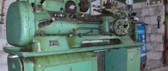
The specifics of manufacturing certain types of parts require that the axis of rotational motion of the workpiece being processed should be located in a vertical plane. This processing principle is more convenient for parts that have a significant diameter and weight, but at the same time have a short length.
Such parts, in particular, include flanges, disks, flywheels, gears, wheels, etc. It is for the processing of such parts that rotary-type metal-cutting equipment was developed, one of the brightest representatives of which is the 1512 rotary lathe.
History of creation and production
Despite the fact that the 1512 rotary lathe is very popular in our time, it began to be produced quite a long time ago, in the thirties of the last century. The development of this machine, along with similar equipment of other models, was carried out by the team of the Krasnodar Machine Tool Plant named after G.M. Sedina, founded back in 1911.
For a long time, this plant was the flagship enterprise for the development and production of rotary-type lathes. The equipment produced at this enterprise was actively supplied not only to all republics of the former Soviet Union, but also to many countries around the world; many of these machines are successfully used for their intended purpose in our time.
Components
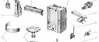
Components of the machine 1516
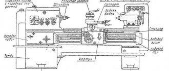
The layout of the machine is classic for single-column rotary-type machines. It contains the following parts:
- faceplate;
- protective casing;
- vertical unit (support);
- control panel (for convenience, placed on a suspension);
- remote control counterweight;
- crossbar;
- cross member drive;
- bed;
- manual drive of the vertical unit;
- vertical support feed box;
- gearbox;
- belt drive casing;
- feed drive;
- lubrication station;
- horizontal unit (caliper);
- box forming the feed for the side support.
Technical parameters and characteristics
Vertical turning lathe 1516 technical characteristics, which are reflected by the following parameters:
- the maximum permissible part size is 1600 mm;
- the permissible size of the part height during processing is 1000 mm;
- permissible weight of the part installed on the faceplate – 6300 kg;
- faceplate, size for installing the part – 1400 mm;
- number of switchable speeds – 18;
- at what speeds does the table rotate – min 5 min-1, max 250 min-1;
- number of feeds for each caliper – 18;
- feed range – 0.03-12.5 mm/rev;
- cutting force, max – 44100 N;
- range of installation speeds – min 5 mm/min, max 1800 mm/min.
Vertical support
- horizontal displacement length – 950 mm;
- vertical displacement length – 700 mm;
- offset angle - 45;
- tool holes – 70Н7 mm;
- holder dimensions, WxH – 25x40 mm.
Cross member
- travel length – 660 mm;
- movement speed – 400 mm/min;
- movement blocking – Yes;
- safety switches (ends) – Yes.
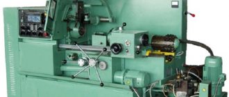
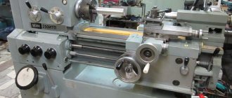
Appearance of machine 1516
Parameters of electrical elements
- supply network, current - three-phase alternating;
- electric motor power:
- main - 30,000 W;
- calipers - 3000 W;
- crossbars - 2000 W;
- lubrication stations - 800 W.
Description of the housing and design
The 1512 rotary lathe belongs to the category of rotary turning equipment; this, in particular, is indicated by the numbers in its model designation:
- 1 – designation of equipment group (lathe);
- 5 – type of equipment (carousel);
- 12 – indicator of the maximum diameter of the workpiece that can be processed (1250 mm).
The design of the 1512 vertical turning lathe is classic for equipment of this type and consists of a number of standard elements.
Dimensions
Considering the technical capabilities of the 1512 rotary lathe, it becomes clear why its dimensions and weight are quite significant. Thus, these characteristics of the machine correspond to the following indicators:
- Equipment dimensions – 2750x2975x4100 mm.
- The weight of the 1512 rotary lathe excluding the weight of the BS is 15,500 kg.
- The weight of the 1512 rotary lathe, taking into account the weight of the aircraft, is 16,500 kg.
Location of controls
The 1512 vertical lathe's controls are ergonomically located on its face, on the overhead panel and on its tool assemblies. Such bodies, in particular, include:
- A handle designed to fix the cutting head of the side support (BS).
- A screw that secures the cutting tool holder in the corresponding sockets of the turret.
- Screw fixing the slider of the vertical support (BC).
- Nuts intended for fixing the rotating skid of the aircraft.
- Handle for connecting to the electrical network.
- A handle designed to fix the traverse (cross member).
- Buttons for turning on the movement of the crossbar in the “up” and “down” direction.
- The square of the worm, which is responsible for the rotating movements of the BC slide.
- Screw fixing the aircraft.
- A flywheel with which the slider BC can be moved in the vertical direction.
- A flywheel with which the aircraft can be moved horizontally.
- Pendant-type control panel.
- A screw designed to fix the BS slider.
- Screw to ensure fixation of the BS itself.
- A flywheel with which the BS slider can be moved in the horizontal direction.
- Flywheel to ensure movement of the BS itself in the vertical direction.
The main body designed to control the 1512 vertical lathe is the pendant console; using the buttons and switches located on its front panel, you can perform the following actions:
- Completely stop the 1512 rotary lathe.
- Use the warning light to indicate that there is no lubrication in the main drive.
- Stop the main drive.
- Start the main drive.
- Turn on and off the brake that holds the aircraft.
- Rotate the tool head and fix the tool being used in its sockets.
- Switch the value of working feeds, as well as installation feeds of the aircraft.
- Switch the direction of movement of the aircraft.
- Use the warning light to understand that the aircraft is in operation.
- Turn on and off the lamps illuminating the work area.
- Using a signal lamp, understand that the BS is in action.
- Switch the direction of movement of the BS.
- Set the required feed value, as well as the installation movements of the BS.
- Turn on or off the brake that fixes the BS.
- Set the required faceplate revolutions per minute.
- Turn on or off the step-constant speed at which cutting is carried out.
- Start the rotation of the faceplate or stop it.
- Start the faceplate jog or cancel it.
Thus, the controls of the 1512 rotary lathe make it possible not only to put into operation all of its components, but also to partially control their technical condition.
Components
The main elements that make up the design of the 1512 vertical lathe are:
Rack
This is a massive hollow structure made of cast iron; it is on it that all the parts and assemblies of the 1512 rotary lathe are attached.
Desktop
This unit is a 1512 rotary lathe, consisting of a faceplate with a spindle mounted on it, a drive device and two supports with bearings. Centering of the work table platform is ensured by roller bearings; in addition, they take on the radial forces that arise when processing parts.
Axial loads, which are formed by the weight of the workpiece and cutting forces, are absorbed by a ring-type sliding guide, which is equipped with a centralized lubrication device.
To select radial clearances, if they appear in the worktable supports, their design includes internal rings with a conical surface, which are tightened using adjusting nuts. The transmission of torque from the drive shaft to the faceplate is ensured by a cylindrical helical gear connected to the main movement drive.
Gearbox
This unit of the 1512 vertical lathe is responsible for transmitting torque from the drive motor to the spindle mounted on the work table. In addition, using this unit, the required peripheral speed of the machine spindle is set.
The design of the gearbox includes six shafts with gears freely sitting on them, which makes it possible to adjust the speed of rotation of the output shaft. Meshing of gears of a certain diameter is ensured by electromagnetic type clutches, activated remotely.
Vertical support unit
It is this that ensures the vertical and horizontal movement of the tool during processing. It is equipped with a turret that can hold up to five tools simultaneously.
Vertical movement is ensured by its guides, and horizontal movement is ensured by guides installed on the crossbar or traverse; it, in turn, can also move in the vertical plane along its own guides. A feed box is attached to the crossbar, which is responsible for the horizontal movement of tools.
Vertical movement of the cross member is provided by a separate drive equipped with an electric motor. The turret head is also equipped with a separate electric drive and worm mechanism, due to which the change of positions occupied by it is ensured. The 1512 rotary lathe can machine conical-type surfaces, which is ensured by the fact that its support can be rotated in both directions at an angle of up to 45 degrees.
Side caliper
Equipped with a 4-position tool holder, it duplicates the orthogonal movements of the vertical support. This solution was implemented in order to reduce elastic deformations occurring in the tool system in each specific part processing scheme, as well as increase equipment productivity due to its ability to simultaneously operate two power units in parallel.
Thus, a side support, in which the tool overhang remains constant during processing, is more optimally used for external turning of a tall workpiece. The use of a vertical support is advisable when it is necessary to process a central hole or trim the end surface of a workpiece of significant diameter.
Gearbox
These are two drive units - one for each of the calipers. The designs of these units, which are completely identical to each other, include a group of shafts with gears installed on them, as well as several electromagnetic couplings.
The drive for this unit is a shaft; it is rigidly connected to the worktable spindle using several gears. At the output of the feed box, two shafts are installed, one of which is responsible for the horizontal movement of the caliper, the second for the vertical movement.
Activation of the required feeds is ensured by selecting one of the combinations of gears, and separate electric motors are used to accelerate the movement of tool assemblies. In the feed box of the 1512 rotary lathe, it is possible to move its supports manually, for which several flywheels are used. This machine unit allows you to obtain 18 working feeds and create the same number of accelerated movements.
Purpose and scope
The numbers in the marking have the following interpretation, if we rely on the domestic classifier:
- 1 – assignment to a specific group of equipment. In this case it is turning.
- 5 – machine type. It's a carousel.
- 12 – characteristic describing the dimensions. 1250 millimeters is the maximum part size for processing.
The name “carousel” has its own history. Essentially, the term refers to how the installation is designed. The main parts include the faceplate with clamping elements. Rotation around a vertical axis makes the device similar to the rides of the same name. The lathe type of machine is the closest in properties to its competitors. They differ in a spindle with a traditional horizontal arrangement. The passport confirms this.
The purpose of both types of devices is turning parts with a short length. But it is the carousel variety that has a wide range of advantages.
- High-quality fastening of components and parts.
- Convenient loading of workpieces.
- The spindle is not subject to bending forces.
- Processing may take longer. 1 – parameter of the relationship between height and diameter.
Among the disadvantages, possible difficulties with chip removal are noted. Diametric measurements also turn out to be inconvenient for many.
Specifications
Full information on the technical characteristics of the 1512 vertical turning lathe is contained in its passport, but even key parameters make it possible to understand what capabilities it has:
| Parameter name | 1512 | 1516 |
| Main settings | ||
| The largest diameter of the product processed by vertical and lateral supports, mm | 1250 | 1600 |
| Maximum height of the workpiece, mm | 1000 | 1000 |
| Faceplate diameter, mm | 1120 | 1400 |
| Maximum weight of the installed product, kg | ||
| at 5-80 faceplate revolutions per minute | 3200 | 6300 |
| at 100 faceplate revolutions per minute | 3000 | |
| at 125 faceplate revolutions per minute | 2700 | |
| at 160 faceplate revolutions per minute | 1900 | |
| at 200 faceplate revolutions per minute | 1300 | 2400 |
| at 250 faceplate revolutions per minute | 1000 | |
| Vertical support | ||
| Maximum horizontal movement, mm | 775 | 950 |
| Maximum vertical movement, mm | 700 | 700 |
| Price for dividing the horizontal and vertical movement dial, mm | 0,05 | 0,05 |
| Horizontal and vertical movement per one revolution of the dial, mm | 2,5 | 2,5 |
| Maximum angle of rotation of the caliper slider, degrees | 45 | 45 |
| Caliper slider rotation dial division price, min | 1 | 1 |
| Caliper slider rotation scale division value, deg | 1 | 1 |
| Diameter of caliper turret holes, mm | 70A | 70A |
| The largest cross-sectional dimensions of the cutter holder (width x height), mm | 25 x 40 | 25 x 40 |
| Horizontal caliper (side) | ||
| Maximum horizontal movement, mm | 630 | 630 |
| Maximum vertical movement, mm | 1000 | 1000 |
| Price for dividing the horizontal and vertical movement dial, mm | 0,05 | 0,05 |
| Horizontal and vertical movements per one revolution of the dial, mm | 2,5 | 2,5 |
| Cross member | ||
| Maximum displacement, mm | 660 | 660 |
| Travel speed, mm/min | 400 | 400 |
| Switching stops | Available | Available |
| Blocking movement during cutting | Available | Available |
| Machine mechanics | ||
| Number of faceplate speeds | 18 | 18 |
| Faceplate revolutions per minute | 5 — 250 | 5 — 250 |
| Number of caliper feeds | 18 | 18 |
| Vertical and horizontal feeds of calipers, mm/rev | 0,03 — 12,5 | 0,03 — 12,5 |
| Maximum permissible cutting force with two supports, kgf | 4500 | 4500 |
| Speed of installation movements of calipers, mm/min | 5 — 1800 | 5 — 1800 |
| Drive and electrical equipment of the machine | ||
| Type of supply current | AC three-phase | AC three-phase |
| Main drive electric motor: | ||
| power, kWt | 30 | 30 |
| Rotation speed, rpm | 1460 | 1460 |
| Electric motor for installation movements with caliper: | ||
| power, kWt | 3 | 3 |
| Rotation speed, rpm | 1365 | 1365 |
| Electric motor for moving the crossbar: | ||
| power, kWt | 2 | 2 |
| Rotation speed, rpm | 900 | 900 |
| Lubrication motor: | ||
| power, kWt | 1,5 | 1,5 |
| Rotation speed, rpm | 1450 | 1450 |
| Turret head rotation and clamping motor: | ||
| power, kWt | 0,8 | 0,8 |
| Rotation speed, rpm | 1450 | 1450 |
| Dimensions and weight of the machine | ||
| Machine dimensions (length x width x height), mm | 2750 x 2975 x 4100 | 3170 x 3030 x 4100 |
| Machine weight, kg | 16 500 | 20 000 |
Electrical diagram
The entire electrical system of the 1512 rotary lathe is located in a special niche in its body. The main functions for which this system is responsible are:
- control of the faceplate operation;
- start-up of the 1512 rotary lathe in working mode, as well as in jog mode;
- changing the speed of rotation of the faceplate and ensuring a constant cutting speed when turning end surfaces using the upper support;
- faceplate stop;
- selecting the value of the working feed and turning it on;
- selecting a value, turning adjustment movements on and off.
Electric motors, limit switches and other electrical controls are responsible for performing the above functions of the 1512 vertical lathe. Thus, the following set of drive motors is installed on the machine of this model:
- the engine responsible for the operation of the main drive of the machine;
- a motor driving an oil pump;
- a motor driving the cross member (traverse);
- a motor responsible for the installation movements made by the upper and side calipers;
- an engine that provides operation of the lubrication system.
To operate the 1512 vertical lathe, voltage values with the following values are used:
- 380V – power supply of the main power circuits;
- 110V – power supply to single-phase electric motors and magnetic starter coils;
- 36V – power supply to the motor responsible for the stepper finder selection circuit;
- 24V – power supply of lamps responsible for lighting, as well as electrical circuits of electromagnetic couplings;
- 90V – power supply to the coils installed in the step finder.
Kinematic diagram
The kinematic diagram of the 1512 rotary lathe contains the following circuits:
- high-speed traffic;
- serves made by the Armed Forces;
- serves made by the BS;
- rapid or installation movement of calipers and crossbars (traverse).
The high-speed movement chain is responsible for transmitting the required rotation speed to the faceplate of the 1512 lathe. This chain includes an electric motor that drives the V-belt drive and a set of movable gear blocks that are part of the gearbox. Switching the rotation speeds of the faceplate, the number of which theoretically can reach up to 24 (practically 18), is carried out by using electromagnetic clutches.
The caliper feed boxes have the same kinematics; they are directly connected to the faceplate shaft, which is how they work. The design of these machine components also consists of a set of gears switched by means of electromagnetic couplings.
The accelerated movement of both calipers is ensured by a separate electric motor. Also, due to a separate electric motor and two lead screws, the vertical movement of the crossbar (traverse) of the machine is carried out.
Machine weight
The weight of the 1512 vertical turning lathe, depending on how it is equipped with additional components, may vary, but in the basic configuration it is 16,500 kg. Most significantly, the weight of the machine is influenced by the presence or absence of a side support.
Passport (operating instructions)
Machine device
Gearbox
The operator’s interaction with the gearbox occurs through a hand-held remote control placed outside the processing area on a special hanging device. In this case, the operator has the opportunity to move around the part without leaving the machine controls.
Changing the gear ratios at the input and output of the gearbox is carried out by a controlled clutch of six shafts with gears. To ensure smooth transmission of motion, all gears are helical and are in constant engagement. The gears are affected through electromagnetic couplings connected to the control unit. A wide range and smooth gear shifting is provided by various combinations of clutch engagement and disengagement.
Instead of special braking devices in the gearbox, the simultaneous activation of several clutches in two different kinematic chains is used to stop the shaft. Depending on the rotation speed and mass of the workpiece, the braking time ranges from 3 to 11 s.
Due to the large mass of the rotating parts, imparting angular velocities close to maximum to the fixed part occurs through a stepwise change in gear ratios between the main power electric motor and the vertical spindle.
bed
The bed unites all the main components of the machine, ensuring their correct relative position and pattern of movement. The connection between the table and the platform for securing the part is made with pins, which ensures the absence of vibrations and the rigidity of the joint, which facilitates the processing of parts with high precision.
TIP: When choosing the location of the machine's workplace in the workshop, it makes sense to place the equipment in such a way that it would be possible to install massive parts using a local crane beam.
The gearbox is located inside the frame. Under the gearbox there is a container used as a reservoir for lubricant, from which the main system of lubricant supply tubes for the table and gearbox is fed.
Between the faceplate and the upper part of the table there is a developed system of grooves that serves to drain the lubricant coming out of the table body. The oil drain works in such a way that waste from processing the part does not fall into the gap between the two rotating surfaces.
There are no protective shields between the workpiece and the operator in favor of better visual control of the cutting process.
On the side wall of the frame there is a gear oil pump that supplies oil to all working elements through tubes.
Upper caliper
Structurally, the upper support includes the following components: a turret with a holder that moves linearly along the corner slide; cross slides located below and moving horizontally along the crossbar; corner slides located on top of the turning part; drives for automatic caliper feed, rotation and installation of the turret head.
The caliper is driven along the horizontal guides of the cross member through a lead screw that is in permanent engagement with the main worm shaft of the feed control box.
To eliminate the backlash that occurs during long-term operation, the transverse slide is equipped with pins and wedges located on the reverse side and providing support for the slide on the longitudinal guides. To adjust the distance between the caliper and the lower guide, two damping devices are used, structurally presented in the form of a roller mounted on a needle bearing, rolling along a horizontal cross member.
Advantages and disadvantages
Naturally, the main features of the 1512 vertical turning lathe include the fact that it can be used to perform a wide range of technological operations. So, using this machine, you can:
- processing of holes using a rod-type tool;
- boring of holes of both through and stepped type;
- cutting circular grooves;
- grinding of ends and ledges;
- turning the outer surfaces of parts with cylindrical and conical configurations.
If you equip the 1512 rotary lathe with additional attachments, which is possible, then its technological capabilities become even wider. So, when using such equipment you can do:
- lapping and rolling using rollers;
- grinding and superfinishing;
- threading and deep drilling;
- processing of nonlinear surfaces, including spherical configurations.
If we talk about the disadvantages of this, they include difficult removal of chips and the inconvenience of measuring the diameters of the workpieces. In addition, it should be taken into account that the 1512 vertical turning lathe has a significant mass, so its installation requires appropriate preparation of the base.
Kinematics of machine 1516
The kinematic diagram of the machine is designed in such a way that it provides the required table rotation speeds and feed rates of the working parts. The use of electric couplings makes it possible to change speeds without stopping the machine.
To facilitate repairs, the gearbox was designed so that its parting surface is parallel to the axes of the shafts. It is impossible to set the highest table rotation speed. The adjustment is carried out in stages, step by step.
The gearbox is equipped with brakes for good braking of the table.
Kinematic diagram of machine 1516
The rotation on the faceplate is removed from the gearbox by passing through cylindrical and cone-shaped pairs of wheels, and then onto the faceplate wheel. Ease of rotation is provided by a pair of bearings.
Boxes providing tool feeds are coordinated with the gearbox using a splined shaft. Toothed ears do not move along the shafts. Rotation transmission occurs when the electric couplings are turned on. Accelerated movement is ensured by a separate electric motor.
The crossbar drive is provided by two helical pairs. For safety, it is attached manually. The crossbar motor control circuit provides its reverse to match parallelism with the working surface. A shift of 1 tooth provides a movement of 0.005 mm.
Best xiaomi DVR 2022 - TOP 4 best rating
Changing positions of the turret head occurs due to the rotation of the shaft on which the head sleeve, worm and brake clutch are mounted. After turning by 72 (1/5 part of the circle), the stop turns on the microswitch and clamping occurs, the shaft rotates back.
In the operating instructions, you can get acquainted with methods of safe operation of the machine, maintenance periods, lubrication points and lubrication intervals, installation and transportation requirements, and much more.
If you find an error, please select a piece of text and press Ctrl+Enter.
Instructions for use
Before you start using the machine of this model, you should keep in mind that work on it can only be carried out by persons who have thoroughly studied its structure, principle of operation and control, as well as who have undergone detailed safety instructions. In addition, under no circumstances should you start using the equipment if it is missing the V-belt drive casing and the faceplate guard.
There are several simple rules, the observance of which will allow you to protect yourself when working on the 1512 rotary lathe. These rules, in particular, include:
- before starting work, you should check the reliability of fastening the workpiece;
- cleaning and cleaning should only be carried out when the machine is completely turned off;
- it is impossible to remove chips during its operation;
- measurements of the workpiece should be performed only after turning off the rotation of the faceplate;
- you cannot work if the electrical equipment is faulty;
- Before performing maintenance on the machine or repairing it, you should disconnect it from the electrical network;
- foreign objects must not be left on the equipment faceplate;
- When setting up and adjusting the machine, you should be very careful when handling its moving mechanisms.
All the main controls of the 1512 vertical lathe are located on its pendant console. Each of these controls has a symbol next to it that makes it easy to understand their purpose. Thus, if you carefully study the machine and its operating instructions, a specialist should not have any problems when working on it.
Description of the hydraulic circuit of the model 1541 rotary machine
Control of the main drive of the machine. When the faceplate rotation speed selection handle is set to the position corresponding to the required rotation speed, a switching circuit for the electromagnets of distributors 6, 7, 8, 9, 10 is prepared. Pump 3, through filter 1 and check valve 2, sucks oil from the hydraulic tank and through plate filter 4 along the line 29 supplies it to the distributor 26, which is turned off at this time. Then the oil along line 35 through the needle throttle 24 enters under the locking piston of the cylinder 22 for fixing the position of the gears and lifts the locking piston up, thereby releasing the gear shift rods of the gearbox. Having risen upward, the locking piston allows oil access to the oil distributor and from it into the cavities of the gear shift cylinders corresponding to the selected rotation speed. Distributor electromagnets 6, 1, 8, 9, 10 are switched on.
When you press the “Start faceplate” button, the distributor electromagnet 26 is turned on and the oil enters the clutch engagement cylinder 13. The cylinder rod begins to move to the right until the drain hole opens. The clutch forks must be adjusted so that in this position the clutch begins to work with slipping, rotating the gearbox gears at a “creeping speed”. At the same time, oil enters cylinder 23 under the piston, which rotates the gearbox gears through a rack to facilitate shifting.
When switching to the start position of the distributor 26, line 35 is switched on to drain. No longer held in the upper position by oil pressure, the piston-retainer of cylinder 22 tends to fall down under the action of a spring. To prevent the gears from becoming tooth-to-tooth, switching is performed at the “creeping speed” of the clutch.
Having descended, the piston-clamp of the cylinder 22 for fixing the position of the gears closes the drain hole of line 32, and the starting clutch is fully engaged. At the same time, line 34 is closed and the pressure is removed from cylinders 15, 16, 17, 18, 19, 20, 21, 25, and line 35 is turned on to drain and the spring returns the piston of cylinder 23 to its original position.
When you press the “Stop faceplate” handle, the electromagnet of the distributor 26 is turned off and its spool is moved by a spring to the upper position. Oil is supplied to brake cylinder 14 and the faceplate stops.
Throttle 12 is used to adjust the activation time of the working clutch and brake. Instant activation of the working clutch or brake when switching the faceplate rotation speed can lead to an accident.
Throttle 24 is used to adjust the lowering time of the latch. When lowered quickly, the lock will lock the triple gear unit in the middle position, preventing it from moving from one extreme position to another. In this case, the rotation speed of the faceplate will not correspond to the selected one, and when braking, when the latch rises, the triple block switching will continue. To prevent this phenomenon, the system is equipped with a locking mechanism with a microswitch, which eliminates the possibility of turning on the distributor 26 if the position of the triple gear block does not correspond to the position of the rotation speed selection handle.
The hydraulic system of the machine provides for the possibility of abruptly starting and stopping the faceplate when using its two lowest rotation speeds, which is carried out using distributor 11. This distributor is turned on when using all faceplate rotation speeds except the two lowest indicated. When you set one of the two lowest rotation speeds with the rotation speed selection handle and turn on the “Start” button of the faceplate again, the distributor 11 is turned off, and the oil passes both through the throttle 12 and through the grooves of the valve spool 11, which ensures a quick supply of oil to the operating cylinder 13 clutch When the faceplate is turned off, the oil is also drained through distributor 11, which ensures an abrupt stop of the faceplate.
The cross member is released as follows: oil is supplied by pump 3 through line 29 to the distributor 6. When one of the cross member movement buttons is pressed, the distributor 6 is turned on, and oil through line 31 enters the cross member clamp cylinder 5 and releases the cross member clamping arms; then the limit switch 5VK turns on the motor for moving the crossbar and its movement begins. At the end of the movement, the engine turns off and, at the same time, the distributor turns off, stopping oil access to cylinder 5 and connecting cylinder 5 to drain line 30. Under the action of a spring, the cylinder returns to its original position.
Warranty and DIY repairs
Organizations engaged in the sale of new, refurbished or modernized metal-cutting equipment must provide warranties for it. The period of such a guarantee, depending on the technical condition and age, can range from 6 to 12 months.
Despite the fact that the 1512 rotary lathe is a rather complex piece of equipment in technical terms, some types of its repairs can be performed independently. The most common of these types of repairs include:
- replacement of bearings in machine components;
- restoration of guide elements;
- replacement of hoses and pipelines of the lubrication system;
- repair of protective fences;
- repair of the electrical part of the machine;
- replacement of fasteners in units.
Naturally, in order for the repair of such equipment to be carried out efficiently, the specialist performing it must have the appropriate qualifications.