Description
In 1930, the Moscow Machine Tool Plant decided to develop a new standard lathe, abbreviated as TS. Somewhat later, it was renamed DIP-200 - Let's Catch Up And Overtake
, according to the main slogan of the first five-year plan, where 200 is the height of the centers above the frame.
from the German company VDF
was chosen as a prototype . In April 1932, preparations began for the release of the first batch of DIP-200 machines.
On April 25, 1932, the first Soviet universal screw-cutting lathe with a gearbox, DIP-200, was assembled and tested. By the end of 1932, 25 DIPs were produced.
IN 1934
year, the Moscow Machine Tool Manufacturing Plant is mastering the production of heavy universal screw-cutting lathes DIP-300(1d63), DIP-400(1d64), DIP-500(1d65).
IN 1944
In the year, the production of these machines was transferred to
the Ryazan Machine Tool Plant RZS, founded in 1944, the Tbilisi Machine Tool Plant named after. Kirov and Yeisk Machine Tool Plant .
In 1956
The Ryazan Machine Tool Plant produced the first industrial batch of machines of the DIP-300 series - model - RMC 1400, 2800.
IN 1968
The next generation of the series was launched into production - model 1m63.1m63B.
WITH 1973
year, the beginning of serial production of lathes: 16k30, 16k30F3, 1M63BF101, 16M30F3, 1P756DF3.
Tbilisi Machine Tool Plant named after. Kirov produced machines: 1D63A, 1M63D, 1M63DF101.
IN 1992
year, the beginning of serial production of the 1M63N machine, the latest model of the DIP-300 series.
Operating rules
When installing and operating the 163 screw-cutting lathe, the user of this equipment must follow the instructions set forth in Chapters 1 and 2 of its Operating Manual. They include the following sections:
- safety precautions;
- installation, installation and first start-up procedure;
- setup and operating modes;
- adjustment;
- Lubrication system;
- specification of wearing parts.
The procedure for commissioning and operating machine 163 does not differ from similar turning equipment. The only thing that attracts attention is the very detailed instructions on setup and operating modes.
DIP-300 universal screw-cutting lathe. Purpose and scope
The universal screw-cutting lathe model DIP-300 (according to the classification ENIMS 1d63 ) is the first Soviet machine with a gearbox and a processing diameter over the bed of 615 mm, like all other DIPs (DIP-200, DIP-300, DIP-400, DIP_500) , developed and produced at the Moscow machine tool plant Krasny Proletary from 1930 to 1950.
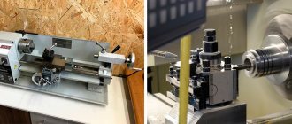
The DIP-300 lathe is designed to perform a wide variety of work on centers, collet or jaw chucks for ferrous and non-ferrous metals, including turning cones, as well as for cutting metric, modular, and inch threads.
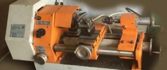
The DIP-300 (1d63a) lathe is capable of processing relatively large workpieces with a diameter of up to 615 mm and a length of 1500 or 3000 mm.
The front end of the spindle is threaded M120 x 6, the internal Morse taper is 5, the hole in the spindle is 70 mm, the diameter of the processed rod is 68 mm.
The spindle of the DIP-300 (1d63a) machine is mounted on double-row roller bearings at the front and in a tapered roller bearing at the rear. The axial load on the spindle is carried by a thrust ball bearing.
The spindle receives 18 stages of forward and reverse rotation frequencies from a six-shaft gearbox in the headstock of the machine. Setting the desired speed is carried out by three handles on the front wall of the headstock.
Starting, stopping and activation of accelerated reverse motion is carried out by a friction plate clutch. The clutch is controlled by handles on the frame at the headstock and on the apron.
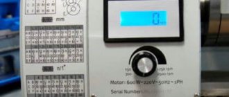
The motion is supplied to the input shaft of the gearbox through a belt drive from an asynchronous electric motor with a power of 10 kW.
Front end of the spy
The shaft is made according to GOST 12593 (DIN 55027, ISO 702-3-75) for a rotary washer, with a centering short cone 1:4 (7°7′30″), nominal cone diameter D = 139.719 mm, nominal size of the spindle end - 6. Internal (tool) spindle cone - Morse 6.
- Nominal cone diameter D = 139.719 mm, nominal spindle end size - 8
- Internal (tool) spindle cone - Morse 6
- Standard diameter of the lathe chuck - Ø 250, Ø 315, Ø 400, Ø 500 mm, version - type 2 (for a rotary washer)
- Through hole diameter - Ø 47 mm
- The largest diameter of the rod is Ø 45 mm
feed box makes it possible to cut (without a step increasing link):
- metric threads with pitch from 1 to 192 mm
- inch threads from 24 to 1/4 threads per inch
- modular threads with modules from 0.5 to 48
- pitch threads from 96 to 7/8
without changing gears on the guitar.
The feed box receives movement from the gearbox through the guitar - replaceable gears with an angle. The headstock includes mechanisms that make it possible to change the direction of movement of the caliper and speed up this movement (increase the thread pitch) by 4 and 16 times.
To produce high-precision threads, the lead screw can be connected through the guitar's replacement gears in addition to the feed mechanism.
The caliper receives feeds along the running roller: longitudinal from 0.10 to 1.6 mm and transverse from 0.04 to 0.59 mm per spindle revolution.
apron of the DIP-300 (1d63a) lathe is equipped with a falling worm mechanism, which makes it possible to automatically turn on the feed from the lead screw when cutting threads in both directions and at the same time protects the machine from damage in case of overload. Disconnection is carried out with an accuracy of 0.02 mm from the stop on the frame.
Specifications
Like most turning equipment, the 160th screw-cutting lathes were produced in two modifications, in which the maximum length of longitudinal processing differed by a factor of two. In the standard version, the center-to-center distance is 2800 mm, and the turning length is 2520 mm. In the shortened version - 1400 and 1260 mm, respectively.
The maximum turning diameters (according to the passport) for this machine are:
- above the guides - 630 mm;
- above the carriage - 350 mm.
The through hole in the spindle in early models was Ø70 mm, later it was increased to 80 and 90 mm. The diameter of the three-jaw chuck is 320 mm. The rated power of the spindle drive motor is 14 kW.
Specification of controls for screw-cutting lathe DIP-300 (1d63a)
- Handle for setting the spindle speed
- Handle for setting the spindle speed
- Handle for reversing the caliper stroke
- Handle for increasing thread pitch
- Handle for setting the spindle speed
- Handle for installing Whitworth and metric threads
- Handle for setting thread pitch
- Feed shift knob (Norton cone)
- Handle for installing metric and modular threads
- Handle for turning on the lead screw or shaft
- Handle for turning on and reversing the machine
- Handle for reversing the travel of the caliper during turning
- Handwheel for manual longitudinal movement of the caliper
- Handle for turning off the feed and turning it on after automatic installation
- Handle for switching longitudinal and transverse feed and locking the lead screw nut
- Handle for turning on the lead screw nut
- Handle for turning on and reversing the machine
- Handle for manual cross feed of caliper
- Handle for securing the cutting head
- Handle for feeding the cutting sled
- Handle for securing the tailstock quill
- Push button station
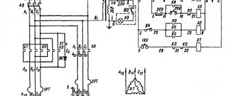
Control of screw-cutting lathe DIP-300 (1d63a)
Gearbox
Depending on the working position, starting, stopping and changing the direction of rotation of the spindle is done by handle 11 at the headstock or handle 17 at the apron. These handles control the two-way slip plate clutch and brake located inside the gearbox. The brake operates automatically in the middle disengaged position of the clutch, ensuring a quick stop of the gearbox mechanism and spindle. When moving the indicated handles to one of the extreme positions, you need to slowly move them to the middle position, and then vigorously move them to the desired extreme position.
To change the spindle rotation speed, handles 1, 2 and 5 need to be moved only at low speed or when the machine is stopped.
Gearbox
Feeds and threads are set with handles 6(A), 7(B), 9(C) and the Norton cone switch 8 according to the table located on the cover of the box. The lead screw or lead roller is turned on using handle 10(D). To directly transfer rotation from the guitar to the lead screw, the feed box is turned off with handle 6(A), and handle 7(B) is placed in the middle position. This may be necessary when cutting high-precision threads or with a special pitch using a special set of replacement gears on the guitar. It is possible to rearrange the feed box handles only at low speed.
Apron and caliper
The caliper feed mechanisms are turned on and off by the handle 14 of the falling worm located inside the apron. Manual feed of the caliper is carried out using handles 18 and 20.
Automatic shutdown of the longitudinal and transverse feed of the caliper is carried out using a falling worm mechanism at the moment of overload under the influence of a large cutting force, or other resistance (focus on the frame) along the feed direction. This mechanism protects the machine from damage and makes it possible to obtain precise dimensions of the product when working against the stop. For this purpose, rotation is transmitted to the worm and worm wheel from the worm shaft through a coupling sitting on the shaft, which engages with its screw protrusions on the worm with the same protrusions of the worm under the action of spring pressure. When the resistance in the transmission system of the caliper and apron increases, reaching a value for which the adjusted spring pressure on the clutch is not designed, the worm shaft, continuing to rotate, will force the clutch, through the screw protrusions of the worm, to push away from it and compress the spring.
During this movement of the coupling along the roller, it turns the lever with handle 14, which supports the worm in a raised position and engaged by the worm gear; the worm falls and disengages from the gear. To turn on the feed, the worm is engaged with the gear by lifting it using handle 14.
When securing the tool holder head of the caliper with handle 19, it is necessary to ensure that the fixing pin fits into the hole on the lower plane of the head. This pin should not be removed, since it helps ensure correct installation of the head. To secure the support to the frame when turning transversely or turning the upper part of the support, it is necessary to tighten the clamping bar of the bed guides with a bolt with a protruding square head on the part of the carriage in front of it on the right side.
Tailstock
Transverse movement of the tailstock body along the bridge, necessary when turning conical products, is carried out using 2 screws 1 on the front and rear sides in the lower part of the body. After loosening screw 2, which presses the transverse front guide plane of the housing groove to the protrusion of the bridge, loosen the screw on the side where you want to move the headstock, and tighten the opposite screw 1. Screw 2 is tightened again after installation is complete. Setting the center of the headstock exactly in the center of the spindle is done by aligning the marks on the “K” plates located on the back side of the bridge and the headstock body. In relation to the bridge, the headstock can be shifted by 10 - 15 mm. To move the tailstock quill, you must first use handle 21 (see control diagram) to release the clamp with which the quill is secured when working in the centers.
Emphasis
A stop, adjustable and fixed on the bed, is provided for turning a product to a certain length during longitudinal turning by automatically turning off the feed when it comes into contact with the carriage stop. The emphasis is installed on the frame guides at the beginning by eye and is strengthened with a clamping screw, and then the adjustment screw is used for precise installation.
Adjusting the working parts of the machine
Adjusting the spindle bearings of the DIP-300 machine
The front conical journal of the spindle rotates in a special adjustable double-row roller bearing with cylindrical rollers. To obtain play, the front spindle bearing is adjusted from inside the headstock by tightening the inner ring of bearing 1 using nut 2.
Adjustment of the rear tapered bearing 3 together with the thrust ball bearing 4 is carried out from the outside of the headstock using nuts 5. After adjusting the bearings, you should check the spindle for radial release. To do this, a mandrel with a conical tail (80 metric cone) and a long cylindrical part of 50 - 55 mm of at least 300 mm is inserted into the conical hole of the spindle.
The tip of the indicator is brought to the centering neck of the spindle and the spindle is pressed out manually using the cylindrical end of the mandrel. In this case, the deviation of the indicator needle should not exceed 0.015 mm. In addition, the spindle should be easily turned by hand if the clutch is placed in the on position.
The front spindle bearing No. 3182128 has main dimensions of 140 x 210 x 53.
Lubrication of the spindle bearings is ensured by the flow of oil when splashed into the existing recesses in the upper part of the gearbox.
Adjusting the friction plate clutch of the gearbox (Fig. 2)
If the friction clutch slips during the working stroke, it must be adjusted immediately, because the friction of the discs will heat up greatly and the machine will not work normally. The friction clutch is adjusted using pressure nuts 1 screwed onto ring 2. The pressure nut can be rotated only after the latch 3 is pressed into ring 2. When the clutch is engaged, one of the ends of the rocker arm 4 must be under the horizontal plane of the groove of the shift clutch 5 .
Adjusting the lateral movement of the tailstock of the screw-cutting lathe DIP-300 (1d63a)
Elimination of slack (play) in the guides of the lower and upper support of the screw-cutting lathe DIP-300 (1d63a)
Eliminating slack in the support guides of the DIP-300 machine (1d63a)
When play appears, the corresponding wedges 1 or 2 are tightened using screws 3 and 4 screwed into the ends of the upper and lower parts of the support.
Adjusting the vertical clearance in the rear guide of the slide carriage of the screw-cutting lathe DIP-300 (1d63a)
Adjusting the gap in the carriage guide of the DIP-300 machine
The gap between the rear guide of the carriage and the bed is adjusted by tightening the strips 1 with screws 2 and fixing the latter with lock nuts 3. After adjustment, the gap should be no more than 0.02 mm.
Elimination of the backlash of the screw for the transverse movement of the support of the screw-cutting lathe DIP-300 (1d63a)
Eliminating the backlash of the cross-travel screw of the support of the DIP-300 machine. The
“backlash” of the cross-screw of the caliper, which occurs when the nut is worn, can be eliminated by tightening the wedge 3 inserted between the halves of the nut. First you need to loosen screw 1 and after selecting the backlash, tighten it again. The “backlash” of the cross-feed screw should be no more than two dial divisions.
Adjusting the tension of the spring of the falling worm of the apron of the screw-cutting lathe DIP-300 (1d63a)
Eliminating slack in the support guides of the DIP-300 screw-cutting lathe.
Adjusting the pressure of spring 1 on the clutch of the falling worm with its shaft is carried out by tightening or loosening nut 2 screwed onto the right end of this shaft. When the pressure decreases, the nut should move along the shaft to the right, and when the pressure increases, it should move to the left. When adjusting the spring, do not allow it to be fully compressed “turn to turn”, since in this case the safety clutch loses its purpose and damage to the apron and caliper mechanisms may occur in case of overload. It is recommended to adjust the spring pressure in accordance with the cross-section of the chips removed during processing.
Adjusting the clearance of the guide of the upper and lower halves of the master nut of the lead screw of the DIP-300 (1d63a) screw-cutting lathe
Adjusting the gap of the mother nut of the lead screw of the DIP-300 machine
When play appears, tighten the bar 1 with screws 2 and fix the latter with lock nuts 3.
Limiting the proximity of the upper and lower halves of the lead screw nut of the screw-cutting lathe DIP-300 (1d63a)
Limiting the proximity of the mother nut of the lead screw of the DIP-300 machine
The necessary freedom of rotation of the screw when the nut is on without excessive axial clearance between the threads of the screw and the nut is carried out by moving the thrust pin 1, located in the vertically drilled hole in the lower half of the nut using the screw 2 located below. The screw is fixed locknut 3.
Adjusting the brake band of the gearbox
This is done by changing its tension using the nuts of a bolt attached to the end of the tape. The nuts are located at the top of the rear outer side of the gearbox housing. The adjustment must be made with the electric motor turned off, checking at low speed the braking force and the loosening of the belt when the friction clutch is in the engaged position, both during forward and reverse motion. When checking, the electric motor turns on.
The main advantages of the 1M63 machine
The high popularity of the equipment was ensured by the accuracy and quality of the operations performed, its reliability and durability. Monolithic supports and a rigid base of the 1M63 RMTs 1400, 2800 lathe, wear-resistant guides and other structural elements provided the possibility of high-speed processing of carbide metals. The design and material of the machine bed, spindle and carriage, as well as the reliability of the parts and assemblies used, make it possible to make maximum use of all processing capabilities at high speeds.
Main design features and advantages:
- Wide range of possibilities for using working tools made of hard and special alloys.
- High rigidity of the spindle assembly, lower part of the support and bed. Allows processing at high speeds.
- A special motor ensures longitudinal and transverse movement of the caliper during operation.
- Possibility of adjusting the thread pitch when cutting. To do this, it is possible to change the wheels on the guitar and change the parameters of the feed box of the screw-cutting lathe.
- Movement of the upper part. Necessary for processing long and short conical parts.