Information about the manufacturer of the screw-cutting lathe Umelets
Manufacturer of the table lathe Umelets (SN, SN-1) - Srednevolzhsky machine-tool plant SVSZ , founded in 1876.
The production of metal-cutting machines at the Srednevolzhsky Machine Tool Plant first began at the end of January 1926. The first machine produced at the enterprise was a screw-cutting lathe with a stepped pulley, model TV-155V.
In 1934, the plant created an original screw-cutting lathe, model SP-162 , with 8 speeds and spindle revolutions per minute from 24 to 482. For the first time, an individual electric motor with a power of 1.5 kW was installed on the machine.
During the war years, the plant mastered the production of a screw-cutting lathe 1615
and soon upgraded it, bringing the spindle speed to 1000 rpm.
In 1949, the machine was put into mass production 1616
, in the sixties the models were
1B616 and 1A616
, and from the beginning of the seventies the production of the
16B16 .
Since the 90s of the last century, the SVSZ company has been producing lathes under the SAMAT .
Machine tools manufactured by the Srednevolzhsky Machine Tool Plant, SVSZ, Samara
- 1A616
universal screw-cutting lathe, Ø 320 - 1A616k
screw-cutting lathe with automatic transmission, Ø 320 - 1A616P
high-precision screw-cutting lathe, Ø 320 - 1B811
turning and backing machine, Ø 250 - 1E811
turning and backing machine, Ø 250 - 1P611
universal screw-cutting lathe, Ø 250 - 16B16
universal screw-cutting lathe, 320 - 16B16A
especially high precision screw-cutting lathe, Ø 320 - 16B16KA
especially high precision screw-cutting lathe with automatic transmission, Ø 320 - 16B16P
high-precision screw-cutting lathe, Ø 320 - 16B16KP
high-precision screw-cutting lathe with automatic transmission, Ø 320 - 16B16F3
chuck center lathe with CNC, Ø 320 - 16B16T1
CNC lathe, Ø 320 - 16D16AF1
especially high precision screw-cutting lathe with digital display, Ø 320 - 561
thread milling machine, Ø 400 x 700 - 1615
universal screw-cutting lathe, Ø 320 - 1616
universal screw-cutting lathe, Ø 320 - 1716PF3
CNC lathe, Ø 320 - 5350A
semi-automatic slot milling machine, Ø 150 - Samat 400
high-precision screw-cutting lathe, Ø 400 - Craftsman
table lathe, Ø 175
Craftsman (SN, SN-1) Tabletop screw-cutting lathe. Purpose, scope
Screw-cutting lathes of the Umelets (SN, SN-1) are designed to perform a variety of turning operations, including cutting metric threads. Accuracy class N according to GOST 8.
The table-top screw-cutting lathe "Umelets" is designed for various types of mechanical processing of metal, wood, and plastic products. The machine is manufactured in 2 versions: with manual longitudinal feed of the caliper without additional devices and with feed drive, with milling and woodworking devices. On the first version of the machine you can perform turning and drilling work.
On the second version of the machine, you can perform turning, milling, drilling, planing, and sawing operations.
With the help of simple devices made on this machine by the consumer himself, other work can be performed. The “Unelets” machine can be used in domestic conditions for the manufacture of various household products, in school workshops, in circles at pioneer clubs and docks, and at stations for young technicians.
Umelets table-top screw-cutting lathe is a small machine and is designed for processing small-sized workpieces:
- The largest diameter of the “disk” type workpiece above the bed is Ø 175 mm
- The largest diameter of the “shaft” type workpiece above the caliper is Ø 90 mm
- Center-to-center distance (RMD) - 215 mm
- Through hole in the spindle for processing rods - Ø 15 mm
- Power of the asynchronous electric motor of the main movement - 0.55 kW
- Machine weight - 90 kg
spindle receives 12 stages of forward and reverse (160..3150 rpm) rotation speeds. The spindle rotation speed is determined by the position of 2 V-belts on three pulleys:
- Feed pulley - 4-speed pulley on the electric motor shaft;
- Take-up pulley - 4-speed pulley at the end of the spindle;
- Intermediate - 5-speed pulley on a moving axis.
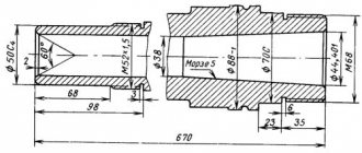
The front end of the spindle is threaded M27 x 2.5 mm.
- Internal (tool) spindle cone - Morse 2
- The standard diameter of the lathe chuck is Ø 80 mm (Chuck 7100-0001 GOST 2675)
- Switching the direction of spindle movement - reverse the electric motor
The feed drive (machine model CH-01) receives movement from the gear on the spindle and transmits it to the lead screw. The feed drive consists of 5 gears - one permanent, coupled to the spindle, and 4 replaceable (guitar).
The choice of the mechanical feed speed and the pitch of the thread being cut is carried out by rearranging the replaceable gears of the guitar in the feed drive. The feed drive provides:
- Cutting 16 metric threads in the range - 0.02..2.5 mm
- Longitudinal feeds - 6 steps - 0.05; 0.075; 0.1; 0.125; 0.15; 0.75 mm/rev
The lead screw is turned on and off by a jaw clutch and is used both for thread cutting and for mechanical feed of the slide during turning.
Characteristics and design features
Since the machine is not professional equipment and has few functional capabilities, it is designed so that a teenager can work on it without difficulty.
The advantage of TV-4 is the indestructibility of the machine. Modern similar foreign-made devices, in the event of any breakdown, will significantly hit your pocket, and besides, it is not always possible to get the necessary part in workshops. The TV-4 model is difficult to break, and finding the necessary spare parts in the event of a breakdown is not difficult.
Overall dimensions of the workspace
TV-4 is a small-sized equipment - 47x102x144 cm and weight - 280 kg. Due to its similar dimensions, the machine is suitable for work in small training workshops.
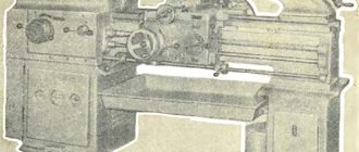
Craftsman General view of a screw-cutting lathe
Photo of a screw-cutting lathe Umelets
Photo of a screw-cutting lathe Umelets
Photo of a screw-cutting lathe Umelets
Photo of a screw-cutting lathe Umelets
Photo of a screw-cutting lathe Umelets
Craftsman Location of the components of a screw-cutting lathe
Location of the components of the Umelets lathe
List of components of a screw-cutting lathe Umelets
- SN.010.000 - Base
- SN.015.000 – Main motion drive
- SN.020.000 – Spindle assembly
- SN.030.000 — Caliper movement mechanism
- SN.031.000 — Feed drive (only for SN-1)
- SN.033.000 – Caliper
- SN.040.000 - Rear headstock
- SN.070.000 – Casing
- SN.071.000 – Fencing
- SN.080.000 – Electrical equipment
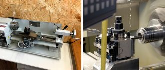
Capabilities of mini machines
A universal mini metal lathe is a real dream for the home craftsman. It allows you to perform a wide range of metalworking work. Having such equipment in your workshop, you no longer need to order expensive replacement parts and wait months for delivery from the supplier. Non-standard small metal parts can be made and modified yourself. Mini lathes are an ideal solution for a garage with a small car service center, a small non-core production workshop, a restoration workshop or a service station.
Structurally, the miniature machine is not very different from its full-size industrial counterparts. Although it is not possible to completely preserve functional diversity in the transition to a miniature size, all basic design elements are preserved:
- Bed.
- Caliper
- Headstock (spindle assembly).
Mini lathe device
The bed is the base, the basic and most massive part on which all other elements are attached, and movement occurs along it. In mini machines, the bed usually has fastenings for installation on a table or, in a more exotic version, on a wall
The support is used to install a processing tool, it can be a countersink, drill or cutter. It also provides a change of position.
The headstock usually contains a belt drive, an electric motor, a gearbox and a spindle. Using various types of chucks, the part for processing is clamped onto the headstock.
Main types of chucks:
- three-jaw;
- four-cam;
- collet;
- wedge;
- lever;
- drill chuck.
The workpiece is fixed in the spindle on the headstock. The tailstock moves along the guides of the base during processing and the tool located on it carries out the necessary processing.
Working on a mini machine
Tabletop mini lathes for metal belong to the category of screw-cutting lathes and can perform a fairly wide range of metalworking operations:
- thread cutting outside and inside the product;
- boring parts;
- drilling;
- applying grooves;
- trimming;
- countersinking.
Craftsman Location of controls for a screw-cutting lathe
Location of controls for a screw-cutting lathe Umelets
Craftsman Specification of controls for a screw-cutting lathe
- Feed movement control handle (turn on mechanical longitudinal feed of the caliper and turn on the feed)
- Spindle activation handle (direct - spindle rotation counterclockwise, reverse - spindle rotation clockwise)
- Handwheel for moving the tool holder
- Quill clamp handle
- Handwheel for moving the quill
- Handwheel for manual longitudinal movement of the caliper
- Handwheel for transverse caliper movement
- Electrical power switch
- Lamp indicating that the machine is connected to the mains
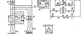
Electrical equipment
The rotation process in the machine is driven by a three-phase electric motor with a power of 1 kW, which is designed to be connected to a 380 V electrical network. In order to use it at home with a single-phase voltage of 220 V, it is necessary to replace the motor or install a special unit.
Important! In case of power failures, interruptions or temporary absence, it is imperative to disconnect the equipment from the power source.
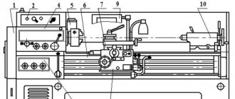
Kinematic chains
In the main movement drive circuit, the rotation of the spindle 14 is carried out from the electric motor 1 through V-belt drives and step pulleys 2, 3, 4. In the feed drive circuit, rotation from the spindle 14 to the lead screw 8 is transmitted through gears 5, 6, a set of interchangeable wheels A, B , B, D, D and claw coupling 13.
Main drive
The drive consists of an electric motor 1 (see Fig. 4), mounted on a bracket 2 and three stepped pulleys 3, 4, 5; The tension of the belts and the change in the center-to-center distance between the pulleys when transferring the belts to other pulley tracks is carried out by moving the pulley 4 mounted on the movable support 6. The drive allows you to obtain 12 operating speeds of the spindle from 160 to 3150 rpm.
Spindle assembly
The spindle assembly (Fig. 5) consists of a spindle 1, the supports of which are two angular contact bearings 2 installed in flanges 3. The flanges are mounted in the base housing. A three-jaw chuck 4 is fixed at the front end of the spindle; a gear wheel 5, which transmits rotation to the feed drive, and a V-belt pulley 6 are fixed at the rear end.
Drive chuck
The driving chuck included in the machine kit is placed in the accessory box. The driving chuck (see Fig. 6), installed instead of a three-jaw chuck and used for processing parts in centers, consists of a thrust center 1 inserted into the conical hole of the spindle, a nut 2 screwed onto the front end of the spindle and a driver 3.
Caliper movement mechanism
The mechanism (see Fig. 7) consists of a lead screw 1, at the straight end of which a flywheel 3 with a dial 2 is attached. The other end of the screw is connected by a coupling 4 to a shaft 5 mounted in angular contact bearings.
Feed drive
The feed drive (Fig. 8, 9, 10), which moves rotation from the spindle to the lead screw, consists of gear 1 (see Fig. 8), replaceable gears 2, 3, 4, 5, cam coupling 6, 7 .
By turning handle 1 (see Fig. 10), attached to the z-axis, clockwise, we move lever 3 with nut 4 and engage the jaw clutch, thereby turning on the caliper feed. Turn the handle counterclockwise to turn on the caliper feed. The transmission option shown in Fig. 8 is used for feeding during conventional turning; in Fig. 9 - for cutting right-hand threads, in Fig. 19 - for cutting left-hand threads. 5.10, Caliper.
The support (see Fig. 11) is designed to feed the cutting tool. The longitudinal feed of the caliper is carried out manually by the caliper moving mechanism or automatically by the feed drive.
When the lead screw rotates, movement is transmitted to carriage 2 through nut 1. Transverse feed of slider 6 is carried out manually by rotating handwheel 3 through screw 4 and nut 5.
Technical characteristics of the Umelets machine
| Parameter name | CH | CH-1 |
| Main settings | ||
| Accuracy class according to GOST 8-82 | N | N |
| The largest diameter of the workpiece above the bed, mm | 175 | 175 |
| The largest diameter of the workpiece above the support, mm | 90 | 90 |
| Maximum workpiece length (RMC), mm | 215 | 215 |
| Maximum cutter height, mm | 10 x 16 | 10 x 16 |
| Spindle | ||
| Diameter of through hole in spindle, mm | 15 | 15 |
| Maximum rod diameter, mm | 14 | 14 |
| Number of speed steps for direct spindle rotation | 12 | 12 |
| Spindle direct rotation frequency, rpm | 160..3150 | 160..3150 |
| Size of the internal cone in the spindle, M | Morse 2 | Morse 2 |
| Threaded spindle end | M | M |
| Caliper. Submissions | ||
| Maximum longitudinal stroke length of the carriage, mm | 215 | 215 |
| Price for dividing the longitudinal feed dial, mm | 0,5 | 0,5 |
| Maximum transverse stroke length of the carriage, mm | 90 | 90 |
| Transverse feed dial division price, mm | 0,05 | 0,05 |
| Number of longitudinal feed stages | ||
| Limits of longitudinal feeds, mm/rev | No | 0,05..0,175 |
| Transverse feed limits, mm/rev | No | No |
| Speed of fast movements of the caliper, longitudinal, m/min | No | No |
| Number of metric threads to be cut | ||
| Limits of pitches of cut metric threads, mm | No | 0,2..2,5 |
| Movable tool holder (Cutter slide) | ||
| Cutting slide dial division price, mm | 0,05 | 0,05 |
| Maximum movement of the slide, mm | ||
| Maximum angle of rotation of the cutting slide, mm | ±90° | ±90° |
| Tailstock | ||
| Dial division price, mm | No | No |
| Quill inner cone size | Morse 1 | Morse 1 |
| Maximum movement of the quill, mm | 40 | 40 |
| Transverse displacement of the tailstock housing, mm | No | No |
| Electrical equipment | ||
| Supply voltage, V | ~220 V | ~220 V |
| Number of electric motors on the machine | 1 | 1 |
| Main drive electric motor power, kW | 0,55 | 0,55 |
| Dimensions and weight of the machine | ||
| Machine dimensions, mm | 770 x 460 x 360 | 770 x 460 x 360 |
| Machine weight, kg | 85 | 90 |
- Universal tabletop machine “Craftsman” SN, SN-1. Operating manual SN.000.000 RE, 1991
- Acherkan N.S. Metal-cutting machines, Volume 1, 1965
- Batov V.P. Lathes, 1978
- Beletsky D.G. Handbook of a universal turner, 1987
- Denezhny P.M., Stiskin G.M., Thor I.E. Turning, 1972. (1k62)
- Denezhny P.M., Stiskin G.M., Thor I.E. Turning, 1979. (16k20)
- Modzelevsky A. A., Muschinkin A. A., Kedrov S. S., Sobol A. M., Zavgorodniy Yu. P., Lathes, 1973
- Pikus M.Yu. A mechanic's guide to machine repair, 1987
- Skhirtladze A.G., Novikov V.Yu. Technological equipment for machine-building industries, 1980
- Tepinkichiev V.K. Metal cutting machines, 1973
- Chernov N.N. Metal cutting machines, 1988
Bibliography:
Related Links. Additional Information
- Classification and main characteristics of turning
- Selecting the right metalworking machine
- Multi-start thread. Methods for cutting multi-start threads on a lathe
- Graphic signs for lathes
- Friction clutch of a screw-cutting lathe
- Lathe repair technology. Repair of bed and support guides
- Lathe repair technology. Repair of headstock and tailstock
- Lathe spindle repair
- Methodology for checking and testing screw-cutting lathes for accuracy
- Directory of lathes
- Manufacturers of lathes
Home About the company News Articles Price list Contacts Reference information Interesting video KPO woodworking machines Manufacturers
Model machine “Skillful hands” K-1
On Friday it was BD, my parent, knowing about my hobby, brought a heavy and pleasantly jingling package. Well, well, well, let's see what's there. Yeah, a Soviet thing that looks like a juicer. I try to lift the cloudy glass and it falls off along with the lid. I put it aside. Yeah, I see a saw. Is this a small circular? Great, it will come in handy, otherwise I’m tired of sawing with a hacksaw.
The right cover is clearly removable... I remove it and see the end of the threaded rod secured with a nut. What is this? A shaft that goes right through? But when turned on, it does not spin, only the saw...
I’m trying to saw off something... a thin sheet chews more than saws, but... why is there so little space to the right of the saw? How am I going to saw off something long, for example, a piece from a blank? The right side clearly needs to come off... I'm trying to pull it... oops! It slides out on round guides, and I see the center on the right, and some kind of toothy crown thing on the left...
I remove the casing... yes, this is... the headstock of the wood lathe and the rear center!
The removed saw and the “toothy thing.”
Obviously not a kit. The box contains only... the core and no other parts. But how can you google, where is the name of the machine? Usually it’s written on the front wall, but there’s nothing here... I turn it upside down...
Yes, here it is:
I googled the name of the brand and realized that many details were missing:
And a lot of questions arose for experienced gentlemen who had this or a similar machine. Because my experience as a lathe includes several lessons in high school (one lesson on metal lathe, one on milling, and several on woodworking lathe), and several hours on a lathe at a factory, but I couldn’t google the instructions for this “juicer”, then questions arose:
1) The glass has turned white, but it is needed to protect it from flying chips. How can it be cleaned? Alcohol and acetone are not used, the polishing wheel scorches even at low speeds. I already had the idea of cutting out the window and inserting a new piece of polycarbonate there. 2) How to work with it? Especially regarding safety precautions. The saw is clear: there is a support table, but no protective cover on top. 3) How to properly secure a piece of wood so that it doesn’t fly into your face? I remember that you need to cut the corners of a wooden block at least to an octagon and then sharpen it to a circle. How to secure it? Stick it into the “crown” and press it with the right center? How strong? I remember that grease is applied to the center. Will regular sewing machine oil work? Or is it better to get solid oil? 4) I noticed that the headstock and rear center are not at all aligned. The difference in axes is up to a centimeter. How critical is this? 5) Is the saw in the photo for wood? Or will it take metal too? 6) Is it possible to fix and process brass parts on such a machine? Shaft thread - M8. 7) I’ll try to make a round attachment for grinding wheels, the missing support for chisels.
In this topic in the comments I will add my experience with the machine, making fixtures and ask any questions that arise. I will be glad to receive answers and advice.
Upd1:
So, I replaced the glass. By the way, in case anyone didn’t know, polycarbonate can be cut and bent quite well with industrial metal cutting machines (unlike plexiglass).
And by a lucky coincidence, the farm had two types of dental grinding wheels. Fine-grained with a sleeve made of something like silumin, almost matching the size of not the saw seat, but the main diameter of the shaft, and a second type of disk made of something between an abrasive wheel and rubber, probably polishing like the green one for a Dremel. I slightly bored out the bushing with a round file and put it on the shaft. There was a hole in the shaft, an M3 screw with a nut went into it, then a disk, then a tube, fixed with a nut. The nut pressed the disk against the screw with the nut, the edge of the nut is fixed by the plane of the disk and should not come out.
Questions: 1) Is the disk secured correctly? Won't it unwind or fly out? 2) How to secure the second type of discs; their seat is a millimeter wider than the shaft. Will I have to sharpen the adapter sleeve? 3) What kind of table should I make for the disk? The same as for a saw, with a slot?
Upd2: I made a stand for the incisors (hand tool). With 2 screw fastening. First attempts (after 18 years) at wood turning:
Upd3: An attempt to cut copper rings on a wooden washer... more unsuccessful than successful.