Universal screw-cutting lathes LT-10, LT-10M, LT-10S, LT-11, LT-11M, LT-11S were produced at the Ivanovo Machine Tool Plant in the village of Ivanovka, Lugansk region (formerly Voroshilovograd) in Ukraine.
The LT-10 machine replaced the outdated screw-cutting lathe DT-10.
Lathes produced by Ivanovsky Machine Tool Plant, Ivanovka village, Lugansk region
- IT-1M, IT-1GM
lightweight screw-cutting lathe Ø 400 - LT-10, LT-11
lightweight screw-cutting lathe Ø 400
LT-10 Lightweight universal screw-cutting lathe. Purpose and scope.
LT-10 screw-cutting lathe replaced the outdated model DT-10 in production and was replaced by a more advanced model IT-1M
.
Lightweight universal screw-cutting lathes, models LT-10 , LT-11, are designed to perform a wide variety of turning operations on centers or chucks and for cutting threads: metric, inch and modular.
Lightweight screw-cutting lathes and LT-11M were intended for use in mobile repair shops , such as KUNG (Today, any insulated booth on a car or trailer is called KUNG).
The LT-10 lathe fits into the DIP-200 standard size and is capable of processing medium and small parts of the Disk type with a diameter of up to Ø 540 mm above the recess in the bed and parts of the Shaft type up to Ø 250 mm above the upper part of the support.
Operating principle and design features of the machine
Roughness of the processed surface V6.
On special order, for an additional fee, the following are supplied: a device for milling small planes, a device for external and internal grinding, a cone ruler and a movable square.
LT-10M and LT-11M machines
The universal screw-cutting lathe LT-10 differs from the LT-11 machine by its increased center-to-center distance. LT-10 has RMC = 960 mm, LT-11 has RMC = 1400 mm.
Machine accuracy class N.
Modifications of the screw-cutting lathe LT-10
- LT-10m - mobile screw-cutting lathe for installation in a car body, RMC = 960 mm
- LT-11m - mobile screw-cutting lathe for installation in a car body, RMC = 1400 mm
- LT-10s - lightweight stationary screw-cutting lathe, RMC = 960 mm
- LT-11s - lightweight stationary screw-cutting lathe, RMC = 1400 mm
Main technical characteristics of the screw-cutting lathe LT-10 (LT-11)
Manufacturer: Ivanovo Machine Tool Plant, Ivanovka, Ukraine.
The main parameters of the machine are in accordance with GOST 18097-93. Screw-cutting and turning machines. Basic dimensions. Accuracy standards.
- The largest diameter of a Disk-type workpiece processed above the bed is Ø 400 , mm
- The largest diameter of the Shaft type workpiece processed above the support is Ø 250 mm
- The largest turning diameter above the recess is Ø 540 mm
- Distance between centers - 960 (1400) mm
- The longest turning length is 875 (1315) mm
- Electric motor power - 2.2 kW, 1430 rpm
- Total machine weight - 1 (1.2) t
Spindle of screw-cutting lathe LT-10 (LT-11)
- Spindle end - threaded M68
- Tool taper - Morse taper No. 5
- Spindle hole diameter - Ø 38 mm
- The largest diameter of the processed rod is Ø 36 mm
- Spindle speed limits per minute (12 steps) - 28..1000 rpm
- Standard chuck diameter - Ø 250 mm
Feeds and threads of screw-cutting lathe LT-10 (LT-11)
- Limits of longitudinal feeds: (38 steps) - 0.03..2.91 mm/rev
- Transverse feed limits: (38 steps) - 0.03..2.60 mm/rev
- Limits of metric thread pitches - (24 pitches) 0.4..10 mm
- Limits of inch thread pitches - (33 pitches) 3..48 threads per inch
- Limits of modular thread pitches - (25 pitches) 0.25..5 modules
Safety precautions
A lathe is a hazardous piece of equipment. Therefore, when working with it, the master must follow basic safety rules. These include:
- working with safety glasses;
- lack of wide and too loose clothing;
- It is prohibited to approach the machine while under the influence of alcohol or drugs.
Before work, be sure to read the operating instructions and undergo detailed safety training at the production site.
The LT-10M universal lathe is popular equipment for small workshops, as well as mobile workshops. Using this equipment and its main modifications, you can perform any turning operations according to a standard scheme. Equipment accuracy class is normal.
Landing and connecting bases for screw-cutting lathe LT-10, LT-11. Spindle
Spindle of screw-cutting lathe LT-10, LT-11
Bed of screw-cutting lathe LT-10
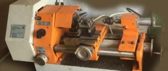
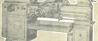
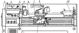
General view of the screw-cutting lathe LT-10
Photo of screw-cutting lathe LT-10
Photo of screw-cutting lathe LT-10
Photo of screw-cutting lathe LT-10
Photo of screw-cutting lathe LT-10
Reservation Rheinmetall Panzerwagen
If we talk about booking, then the “German” has nothing to boast about. In the frontal projection of the turret there is only 30 mm of armor, the hull - 20 mm. For level 10, this is outright cardboard, which will “absorb” even land mines with maximum damage well. It is worth noting that armor plates have practically no corners, so you can’t count on possible ricochets.
The armor of the Rheinmetall Panzerwagen is no different; it would be better to say that there is no armor at all.
Kinematic diagram of screw-cutting lathe LT-10, LT-11
Kinematic diagram of the lathe LT-10m, LT-11m
Main movement chain
The rotation of the product, fixed in the chuck or in the centers, is carried out by an electric motor through a gearbox located in the left cabinet, then through a V-belt drive to the headstock drive pulley and then through the refining gears or, bypassing the bust, directly to the spindle.
Changing the spindle rotation speed is achieved by moving the gear blocks of the gearbox and switching the headstock gear.
Twelve different spindle speeds (from 28 to 1000 rpm) are carried out according to the following kinematic chains: from the electric motor shaft through the friction clutch, the movement is transmitted to the first gearbox shaft. Next, the rotation is transmitted to the second shaft through gears 56-55; 57-59; 58—61, (Fig. 10), and to the third shaft through gears 59—60; 62-63.
Using a V-belt drive, the rotation of the gearbox output shaft is transmitted to the headstock drive pulley. Then, with gear 23 turned on and gear coupling 22 turned off, the spindle rotates at speeds from 28 to 160 rpm. The upper row of spindle speeds is carried out by turning on the gear coupling 22 while turning off the gear 23.
Eccentric K provides the oil pump drive.
Feed chain
Mechanical longitudinal and transverse movement of the caliper during turning is carried out using a roller through the mechanisms of the feed box and apron. Longitudinal movement of the caliper when cutting threads - using a lead screw 43 and a nut 35.
Manual longitudinal movement of the caliper is carried out by handwheel H through gears 29, 31, 30 and rack 40.
The feed box receives movement through gears 17, 19, 18, 16 (headstock mechanism) and interchangeable guitar gears. Next, through gears 14, 13, 11, 10; 15, 11, 10, 14, 13, 12, 9; 15, 11, 12, 9, allowing to obtain gear ratios 2/1, 1/1, 1/2, 1/4, cone gears, gears 7, 8, 25, block, gear 26-27 and gear 28, rotation is transmitted to the running gear the roller, and through the engaged clutch M - to the lead screw.
The feed box mechanism makes it possible to cut the following threads through the lead screw in increments of 4 threads per 1″:
- metric - in increments from 0.4 to 10 mm;
- inch - in increments of 3 to 48 threads per 1″;
- modular - with a module from 0.25P to 5P.
The caliper receives longitudinal feeds from 0.03 to 2.91 mm/rev of the spindles through the running roller, gears 36, 37, 47, 48, 49, 50, 51. 34, 52, 31 of the apron mechanism and rack and pinion gear 30 with rack 40; transverse feeds from 0.03 to 2.60 mm/rev of the spindle - when gear 48 engages with gear 46, through gears 44, 45 and screw 39 with nut 38.
Changing the direction of movement of the caliper is achieved by switching gear 16 located in the headstock.
Transverse movement of the caliper by hand is done through screw 39 and nut 38 using handle G, and movement of the upper carriage is done only by hand through screw 32 and nut 33 using handwheel I.
Gearbox
Gearbox for lathe LT-10m, LT-11m
The gearbox mechanism (Fig. 12) is enclosed in a cast iron housing, the flange of which is attached to the cabinet with four screws.
Rotation to the gearbox mechanism is transmitted from an electric motor attached to the gearbox housing through a disc friction clutch. The gearbox mechanisms transmit six different speeds to the output pulley. The mobile blocks 1 and 5 are controlled by two handles 4 and 9 (see Fig. 4) or 13 and 11 (see Fig. 5). Handle 9 (11) has three positions “1”, “2”, “3”, obtained by turning it to the right and left. Handle 4 (13) has two positions “4”, “5”, obtained by turning it to the right and left.
Headstock
Headstock of lathe lt-10m, lt-11m
The headstock is installed and secured to the top left of the frame. Rotation is transmitted to the spindle from pulley 12 (Fig. 13) directly when gear coupling 17 is engaged or through overdrive. The transfer ratio of the search is 1: 6.3.
The spindle supports are mounted on rolling bearings. The front tapered spindle journal rotates in an adjustable double-row roller bearing, and the rear spindle rotates in a tapered roller bearing. The axial load on the spindle is absorbed by a thrust ball bearing mounted in the rear support.
The spindle is relieved from belt tension forces by installing pulley 12 on gear 15, which rotates in two ball bearings 9.
Spindle adjustment
The spindle of the LT-10M, LT-11M machine is mounted on 3 bearings:
- 19. Front bearing No. 3182116 double-row radial roller, accuracy class A, B, size 80x125x34 mm
- 12. Bearing No. 8115 thrust ball, accuracy class B, size 75x100x19
- 13. Rear bearing No. 7511 tapered roller, accuracy class B, size 55x100x27
Technical characteristics of bearing No. 3182116
Bearing 3182116 is a double row radial roller bearing with short cylindrical rollers, a flangeless outer ring, a tapered bore (1:12), a groove and lubricant holes.
A set of rolling elements with an inner ring are capable of moving relative to the outer one. This standard size, like most roller bearings in this series, is currently produced only with high precision (previously produced in the 5th and 6th accuracy classes), since the main area of application is machines, during operation of which unacceptably high runout occurs due to even small deviations from specified sizes. The main manufacturer of bearings of this design has always been considered the Moscow GPZ-1, but now its production is being transferred to the city of Volzhsky, to a branch of the Aviation Bearing Plant at 15 GPZ (all plants are united under the auspices of the European Bearing Corporation). Currently, two modifications are being manufactured - 4-3182116K and 4-3182116KE, differing in the separator material (brass and polyamide), the price for them is the same. Previously, there were much more of them, primarily in terms of accuracy class. Old bearings, mass-sold in companies of the corresponding profile, can have an accuracy of 2, 5 and 6. You can buy bearings with a quality guarantee, without fear of counterfeit or that you will be sold a used bearing, only from official representatives of EPK (estimated price - about 4700 rubles) selling directly from the factory.
Imported bearings of this size are designated NN3016K (the presence of the letter K in the number is mandatory, as it indicates a tapered fit). In Russia, the most common products are from the following manufacturers: FAG, SKF, IBC. There is also a cheap option for purchasing imported bearings of this type - products from Eastern European manufacturers - ZKL (Czech Republic) and FLT (Poland), however, most often they are sold of illiquid quality, produced in the 80s of the last century, when they were supplied to the country for the needs of collapsed industrial enterprises. It comes in a wide variety of modifications, so sometimes it is the only option for equipment repair.
The estimated price of the highest quality and most expensive imported bearings of this type is about 310 euros when purchased without intermediaries.
Dimensions and characteristics of bearing 3182116 (NN3016K)
- Inner diameter (d): – 80 mm;
- Outer diameter (D): – 125 mm;
- Width (H): – 34 mm;
- Weight: – 1.52 kg;
- Roller dimensions: - 10x10 mm;
- Number of rollers: - 52 pcs;
- Dynamic load capacity: - 122 kN;
- Static load capacity: - 184 kN;
- Maximum rated speed: - 7500 rpm.
Diagram of bearing 3182116 double-row radial roller
Frequency setting
A frequency converter in a machine can be installed instead of a gearbox for a smoother or faster change in spindle speed. For correct operation of the machine, it is necessary to configure the frequency switch on the lathe. For normal starting of the electric motor, the start can be set at a frequency of 10 Hz. The shaft rotation speed is increased using a resistor when the current frequency increases to 400 Hz. Changing the direction of shaft rotation is carried out by switching the converter toggle switch.
Adjustment of screw-cutting lathe LT-10, LT-11
During the operation of the machine, there is a need to regulate individual components of the machine in order to restore their normal operation.
When changing belts, they are removed from the gearbox drive pulley, then the spindle assembly is partially disassembled, cover 13 is removed and the pulley with the belt is lifted up. Pulley 12 is removed with supports, after which the belts are replaced.
In order to dismantle the spindle, you need to unscrew the screws of the front flange 22 and tighten the nuts 5. To facilitate the dismantling of the spindle, the counter gear 19 is mounted on splines. The front support is dismantled along with the spindle. The rear support remains in the bore of the headstock body.
When disassembling the spindle, you should prevent gear 8 with thrust ball bearing 7 from falling to the bottom of the housing.
The spindle is assembled in the reverse order. In this case, you need to make sure that parts 11 and 14 are put in place and in the correct position and secured with screws 10 and 16.
The headstock has two control handles. The right handle is used to turn the overshoot on and off, and the left handle is used to reverse the feed. When engaging the gears, all handles must be brought to a fixed position to avoid breaking the gear teeth.
The front threaded end of the spindle is made according to OST 428.
The chuck faceplate and drive faceplate are equipped with nuts that protect them from unscrewing when the spindle is reversed.
Feed box for screw-cutting lathe LT-10, LT-11
Sketch of the feed box of the lathe LT-10m, LT-11m
Feed box for lathe LT-10m, LT-11m
The feed box mechanism is placed in a closed cast-iron housing, attached with screws to the left side of the frame.
The design of the feed box mechanism allows for different threads and feeds to be achieved by adjusting the guitar of replacement gears and switching the box gears. Set of replacement gears 40; 45; 60; 127 (Fig. 14) is the main one, it allows, without additional reconfiguration of the guitar, to cut metric threads in increments of 0.75 to 10 mm and turn with feeds equal to 0.08–1.24 mm/rev.
The gears are switched by moving their handles 1 and 3 (Fig. 4) or 5 and 7 (Fig. 5). The lead screw or lead roller is turned on by handle 7 (Fig. 4) or 10 (Fig. 5).
The lead screw should only be used when cutting threads to avoid premature wear.
When turning, the mechanical feed of the caliper is carried out exclusively through the running roller.
Tailstock
The tailstock (Fig. 15) is moved along the frame manually. In the required position, the tailstock is secured with a nut.
The tailstock body can be shifted transversely along the slide in both directions from the center line by up to 10 mm, which is sometimes necessary when setting up a machine for turning cones. The displacement is carried out using screws installed in the headstock body.
Apron
The apron (Fig. 16) is a cast box, one of the walls of which is removable.
The apron contains mechanisms that transmit movement to the caliper carriage and the upper slide from the lead screw or lead shaft.
The support feed during turning is carried out using a roller through a transmission of bevel gears.
On the longitudinal feed handwheel there is a dial for the longitudinal movement of the caliper with a division value of 1 mm.
The longitudinal and transverse feeds of the caliper are turned on by turning one handle.
On the right side of the apron there is a handle for turning on the split nut of the lead screw, which provides mechanical feed when cutting threads.
The apron has a locking device that prevents the simultaneous activation of the feed from the lead screw and the lead roller.
Manual movement of the apron is carried out by rotating the handwheel located on the left side of the apron. It is possible to turn off the rotation of the handwheel when cutting threads.
A handle for turning on the spindle drive electric motor is attached to the right side of the apron. To protect against accidental activation, it has a locking device. After completion of work, the handle should be retracted to the right.
Caliper
Thanks to the cross design, the support (Fig. 17) can move longitudinally along the frame guides and transversely along the carriage guides. Both of these movements can be carried out either mechanically or by hand. In addition, the upper slide, which carries a four-position tool holder with four fixed positions, has independent manual movement along the guides of the middle rotary part of the support, which can be rotated ± 60°.
When turning the end surfaces, the support carriage is fixed motionless on the frame by means of a bar and a screw.
Electrical equipment
The main unit that provides mechanical drive of the machine to rotation mode is an asynchronous electric motor operating on direct current.
Direct current provides stepless speed control in the gearbox.
The motor frame is made of low-carbon steel, which eliminates the magnetic conductivity of the unit and the corresponding induction pickups from the side of the magnetic conductive frame.
An inductive power divider connected to the stator winding makes it possible to provide a given number of revolutions, which is then
differentiated by gearbox gears.
The engine and gearbox are connected through pulleys on both devices and a drive belt.
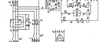
The functioning of electrical equipment is ensured by the following diagram :
Technical data and characteristics of the machine LT-10M, LT-11M
| Parameter name | LT-10M | LT-11M | IT-1M |
| Basic machine parameters | |||
| Accuracy class according to GOST 8-82 | N | N | N |
| The largest diameter of the workpiece above the bed, mm | 400 | 400 | 400 |
| The largest diameter of the workpiece above the support, mm | 250 | 250 | 225 |
| The largest diameter of the workpiece above the recess in the frame, mm | 540 | 540 | 550 |
| Maximum workpiece length (RMC), mm | 960 | 1400 | 1000, 1400 |
| Spindle | |||
| Diameter of through hole in spindle, mm | 38 | 38 | 38 |
| Maximum rod diameter, mm | 36 | 36 | 36 |
| Number of speed steps for direct spindle rotation | 12 | 12 | 12 |
| Spindle direct rotation frequency, rpm (number of steps) | 28..1000 (12) | 28..1000 (12) | 18..1250 (12) |
| Size of the internal cone in the spindle, M | Morse 5 | Morse 5 | Morse 5 |
| Spindle end | M68 thread | M68 thread | 6k |
| Spindle braking | There is | There is | There is |
| Locking the handles from simultaneously turning on the spindle | No | No | |
| Submissions | |||
| Maximum stroke length of the carriage by hand, mm | 875 | 1315 | 900, 1300 |
| Maximum lateral stroke of the caliper, mm | 235 | 235 | 235 |
| Caliper movement by one dial division during longitudinal movement, mm | 1 | 1 | 1 |
| Caliper movement by one dial division during transverse movement, mm | 0,02 | 0,02 | 0,02 |
| Maximum stroke of the upper support (cutting slide), mm | 120 | 120 | 135 |
| Movement of the cutting slide by one division of the dial, mm | 0,05 | 0,05 | 0,05 |
| Number of longitudinal feed stages | 38 | 38 | 50 |
| Limits of longitudinal working feeds, mm/rev (number of steps) | 0,03..2,91 (38) | 0,03..2,91 (38) | 0,05..6 (50) |
| Number of cross feed stages | 38 | 38 | |
| Limits of working cross feeds, mm/rev | 0,03..2,6 (38) | 0,03..2,6 (38) | 0,025..3 (50) |
| Speed of fast movements of the caliper, m/min | No | No | No |
| Limits of pitches of cut metric threads, mm | 0,4..10 | 0,4..10 | 0,25..112 |
| Limits of pitches of cut inch threads | 48..3 | 48..3 | 56..1 |
| Limits of pitches of cut modular threads | 0,25..5 | 0,25..5 | 0,25..56 |
| Limits of pitches of cut pitch threads | No | No | 56..1 |
| Switching stops for longitudinal movement | No | No | |
| Switching stops for transverse movement | No | No | |
| Longitudinal overload protection | There is | There is | There is |
| Locking the handles from simultaneous activation | There is | There is | There is |
| Tailstock | |||
| Maximum movement of the quill, mm | 85 | 85 | 90 |
| Lateral displacement, mm | ±10 | ±10 | ±10 |
| Inner cone, mm | Morse No. 4 | Morse No. 4 | Morse No. 4 |
| Electrical equipment | |||
| Number of electric motors on the machine | 3 | 3 | |
| Main drive electric motor, kW (rpm) | 2,2 | 2,2 | 3 (1430) |
| Cooling pump electric motor, kW (rpm) | 0,125 | 0,125 | 0,12 (2800) |
| Grinding device drive electric motor (optional) 3M, kW | 0,7 | 0,7 | |
| Dimensions and weight of the machine | |||
| Machine dimensions (length width height), mm | 2160 x 1000 x 1400 | 2600 x 1000 x 1400 | 2165 x 960 x 1500 |
| Machine weight, kg | 1000 | 1200 | 1140 |
- Screw-cutting lathes LT10M, LT-11M, LT10S, LT-11S. Manual
- Acherkan N.S. Metal-cutting machines, Volume 1, 1965
- Batov V.P. Lathes, 1978
- Beletsky D.G. Handbook of a universal turner, 1987
- Denezhny P.M., Stiskin G.M., Thor I.E. Turning, 1972. (1k62)
- Denezhny P.M., Stiskin G.M., Thor I.E. Turning, 1979. (16k20)
- Lokteva S.E. Computer controlled machines, 1986
- Modzelevsky A. A., Muschinkin A. A., Kedrov S. S., Sobol A. M., Zavgorodniy Yu. P., Lathes, 1973
- Pikus M.Yu. A mechanic's guide to machine repair, 1987
- Skhirtladze A.G., Novikov V.Yu. Technological equipment for machine-building industries, 1980
- Tepinkichiev V.K. Metal cutting machines, 1973
- Chernov N.N. Metal cutting machines, 1988
Bibliography:
Related Links. Additional Information
- Classification and main characteristics of turning
- Selecting the right metalworking machine
- Multi-start thread. Methods for cutting multi-start threads on a lathe
- Graphic signs for lathes
- Friction clutch of a screw-cutting lathe
- Methodology for checking and testing screw-cutting lathes for accuracy
- Manufacturers of lathes
- Manufacturers of metal-cutting machines
- Directory of lathes
Home About the company News Articles Price list Contacts Reference information Interesting video KPO woodworking machines Manufacturers
Historical facts of Rheinmetall Panzerwagen
In 1957, the West German concern Rheinmetall patented a new model of a light tank. The main innovation of Spz. 57 had a swing turret design that allowed the gun to be lowered to a greater degree than most tanks of the 50s. At the same time, the vehicle had small dimensions and a fairly low profile, which ensured reduced visibility. Thus, even a light tank retained the ability to be equipped with guns of serious calibers (90 mm or even 105 mm), without losing its advantages - speed, maneuverability and low visibility. Since it developed only the turret, without having its own chassis, the new product was offered to other manufacturers for use with their promising chassis. In particular, there were projects of tanks with a turret from Rheinmetall on a chassis from Henschel. The development did not go beyond the design board, and not a single working prototype was created.