Information about the manufacturer of the screw-cutting lathe 1B61
The manufacturer of screw-cutting lathes model 1B61 is the Yerevan Machine Tool Plant named after. Dzerzhinsky .
The plant produced screw-cutting lathes of models 1L61, 1B61, 1P61, 1V61, 1M61, a series of lathes 16L20, 16P16, 16E16. They also produced mechanized and special machines of the ET-23, ET-26, ET-34, ET-41 models, and a multi-cutting machine model ET-50.
Currently, the plant is called Yerevan Machine Tool Production Association ESPO , OJSC. The products produced are universal high-precision screw-cutting lathes 16E25P and 16EG25P with a processing diameter of 500 mm.
Machine tools produced by the Yerevan Machine Tool Plant named after. Dzerzhinsky
- 1B61
universal screw-cutting lathe, Ø 320 - 1B61
universal screw-cutting lathe, Ø 320 - 1L61
universal screw-cutting lathe, Ø 320 - 1M61
- universal screw-cutting lathe, Ø 320 - 1M61P
- high-precision universal screw-cutting lathe, Ø 320 - 2G106P
- high-precision tabletop drilling machine, Ø 6 - 16E16KP
- high-precision screw-cutting lathe with automatic transmission, Ø 320 - 16L20
– lightweight screw-cutting lathe, Ø 400
1B61 universal screw-cutting lathe. Purpose, scope
1B61 universal screw-cutting lathe has been produced since 1958 and was replaced in production by the 1B61
.
1B61 lathe is designed for turning external (diameter up to 320 mm) and internal surfaces of parts (710 or 1000 mm long) with a stepped and curved profile in the axial section.
1B61 screw-cutting lathe is designed for performing various turning operations on centers or a chuck, as well as for cutting metric and inch threads in machine shops in small-scale and individual production.
1B61 machine allows you to perform the following types of turning work:
- Grooving and boring of cylindrical and conical surfaces
- End trimming
- segment
- Cutting metric threads, inch
- Drilling and a number of other works
Operating principle and design features of the 1B61 machine
Starting, shutting down, changing the direction of the main movement is carried out using a reversible magnetic starter.
The rotation speed is changed by switching gears on the front panel of the spindle head.
Quick reversal of the electric motor when cutting threads - by turning handle U20 from the upper extreme position to the lower extreme position and vice versa.
The main drive motor is braked by an electromagnetic clutch at the end of the input shaft in the gearbox.
The front end of the spindle is threaded.
Machine accuracy class N.
Differences between machines 1B61 and 1L61
Center-to-center distance RMC:
- 1B61 - 710, 1000
- 1L61 - 500
Spindle speed:
- 1B61 - 16..2000 rpm (24 steps)
- 1L61 - 10..1250 rpm (24 steps)
Main drive motor power:
- 1B61 - A5I-4; 4.5 kW; 1440 rpm
- 1L61 - AL42/4; 2.8 kW; 1420 rpm
VSN desktop drilling machine. Purpose and scope
VSN machine is designed for drilling holes and cutting threads in small parts made of cast iron, steel, non-ferrous alloys and non-metallic materials in industrial enterprises, repair shops and household workshops.
Main parameters of the VSN drilling machine:
- Maximum drilling diameter: Ø16 mm
- Maximum drilling depth: 100 mm
- Maximum height of workpiece: 400 mm
- Electric motor power: 0.75 kW
- Machine weight: 60 kg
The simplicity of the design ensures ease of control, reliability and durability of the machines.
The drilling depth is measured using a flat scale or stop.
The original design of the belt drive tension allows you to quickly change the position of the belt on the pulleys to obtain the desired cutting speed.
VSN machine allows you to perform the following operations:
- drilling
- countersinking
- deployment
- reaming
- thread cutting
The spindle of the VSN receives 3 rotation speeds from three-stage drive pulleys, which provides a choice of cutting speeds - 450, 1200, 1800 rpm.
The end of the spindle is an external Morse taper KM2, designation B18 according to GOST 9953 (Shortened tool tapers) - shortened cone: D = 17.780 mm, cone length 37.0 mm.
The shortened cone B18 corresponds to a three-jaw drill chuck of the 16th standard size in accordance with GOST 8522 (Three-jaw drill chucks) with a clamping range from 3 to 16 mm.
An example of a symbol for a 3-jaw drill chuck, size 16, with a connecting conical hole B18:
Cartridge 16-B18 GOST 8522-79
Morse cone instrumental shortened
Tool taper - Morse taper is one of the most widely used tool mounts.
It was proposed by Stephen A. Morse around 1864. The Morse taper is divided into eight sizes, from KM0 to KM7 (English: MT0-MT7, German: MK0-MK7). Taper from 1:19.002 to 1:20.047 (cone angle from 2°51'26″ to 3°00'52″, cone slope from 1°25'43″ to 1°30'26″) depending on the size.
Morse taper standards: GOST 25557 (Tool tapers. Main dimensions), ISO 296, DIN 228. In the Russian standard, the KM7 taper is not recommended for use; instead, the incompatible metric taper No. 80 is used. Cones made according to inch and metric standards are interchangeable in everything except the shank thread.
For many applications, the length of the Morse cone turned out to be excessive. Therefore, a standard was introduced for nine standard sizes of shortened Morse cones (B7, B10, B12, B16, B18, B22, B24, B32, B45), these dimensions were obtained by removing the thicker part of the cone. The number in the designation of a short cone is the diameter of the thick part of the cone in mm.
Russian standard for shortened cones GOST 9953-82 (Shortened tool cones).
- B7 - Morse cone - KM0 , D = 7.067 mm;
- B10 - Morse cone - KM1 , D = 10.004 mm;
- B12 - Morse cone - KM1 , D = 12.065 mm;
- B16 - Morse cone - KM2 , D = 15.733 mm;
- B18 - Morse cone - KM2 , D = 17.780 mm;
- B22 - Morse cone - KM3 , D = 21.793 mm;
- B24 - Morse cone - KM3 , D = 23.825 mm;
- B32 - Morse cone - KM4 , D = 31.267 mm;
- B45 - Morse cone - KM5 , D = 44.399 mm.
Where D is the diameter of the cone in the main plane.
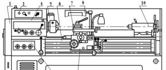
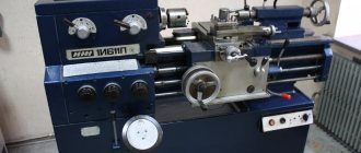
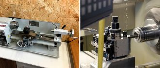
General view of the universal screw-cutting lathe 1B61
Photo of universal screw-cutting lathe 1B61
Photo of universal screw-cutting lathe 1B61
Gearbox control handles for lathe 1B61
Photo of universal screw-cutting lathe 1B61
Photo of a guitar from a 1B61 screw-cutting lathe
Location of controls for screw-cutting lathe 1B61
Location of controls for screw-cutting lathe 1B61
List of controls for screw-cutting lathe 1B61
- U1 - Handle for setting the spindle speed (Fig. 7)
- У2 — Handle for setting the spindle speed (handle selection)
- UZ - Handle for obtaining normal and increased thread pitches, as well as right and left rotation.
- U4 - Handle for setting the feed and thread values, as well as direct activation of the lead screw
- U5 - Handle for setting the type of thread, as well as turning on the lead screw or lead shaft
- U9 - Flywheel for longitudinal movement of the carriage manually
- U10 - Handle for disengaging the roller - gears with rack
- U11 - Handle for turning on the overload clutch
- U12 - Handle for turning on the lead screw, as well as for communicating forward or reverse movement of the caliper in the longitudinal and transverse direction
- U13 - Handle for turning on the mechanical longitudinal or transverse feed of the caliper
- U14 - Handle for manual transverse movement of the caliper
- U15 - Handle for securing the cutting head
- U16 - Handle for moving the upper part of the caliper manually
- U17 — Handle for fixing the quill
- U18 - Handle for fixing the tailstock
- U19 - Flywheel for moving the tailstock quill
- U20 - Handle for turning off and reversing spindle rotation
- U21 - Local lighting switch
- U22 - Switch for connecting the machine to the network
- U23 - Electric pump switch
Feedbox control sketch. Example of setting the thread size /Fig.5/
Feed box control handles for screw-cutting lathe 1B61
It is required to cut metric threads with a pitch of 4 mm.
To do this, handle U5 in the direction of arrow “a” is installed opposite the inscription “metric and modular thread”.
By pulling handle U4 towards you, set the required pitch of section V /table/ against the letter “c”.
Then, pressing handle U4 all the way, set it to the required thread size in increments of 4 mm against the letter “b”.
Basic rules for operating the machine
- Before starting the machine, study its diagram and design, the purpose of the handles and the procedure for switching them.
- When operating the machine, always bring the handles to the locking position.
- Never change gears while moving.
- When turning, use a lead roller; use a lead screw only when cutting threads.
- You cannot straighten workpieces in the centers or guides of the bed: this destroys the machine and deprives it of accuracy.
- To remove the center from the headstock spindle, use a rod with a copper or brass tip.
- When processing parts in the centers, check whether the tailstock is secured against longitudinal displacement. After installing the product, clamp the quill, having previously lubricated the center.
- You cannot work on worn out and clogged centers.
Description of design
Here the user must take into account some nuances.
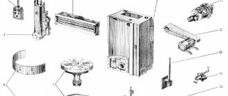
Location of main components
- The main unit is the bed.
Compared to other components, it has minimal weight. The part is mounted on a special platform using appropriate bolts. The bed has two guides. One of them is made in the shape of a “dovetail”, and the second looks like a prism. The support on the frame is held rigidly thanks to such shapes and wedges responsible for adjustment.
- The headstock is usually located on the left.
It is installed inside the grooves in such a way that the user can easily rotate the part a few degrees when the need arises. That is, the center moves relative to the axis without any problems. Then, when processing parts, it is easy to achieve a certain shape.
- The headstock houses the gearbox.
The control levers are located outside. A guitar of replacement gears is mounted in the front. Before cutting the thread, the gears are changed if necessary. The gearbox is the place where you can find the spindle assembly. The spindle itself rotates while maintaining speeds of up to 16-2000 rpm.
The main drive motor of the machine is located in a special cabinet on the left side. Forward and reverse rotation of the spindle is activated at any convenient moment.
- The tailstock is on the right side of the bed.
Various tools are inserted into this part, including the center and dies, taps, and drills.
The tailstock is securely fastened and moves easily along the surface of the bed. The quill stroke is 100 mm.
- An apron through which the shaft and screw pass.
- Caliper.
- Gearbox.
- Electrical cabinet.
- Lubricant and cooling fluid.
- Screen for added protection.
Read also: Device for sawing at an angle
Headstock
The gearbox is involved in the process of transmitting the rotational motion of the spindle pulley. An individual electric motor also takes part here. Type “B” belts ensure the operation of the V-belt drive. The movement goes directly to the spindle through the bust, or bypassing it.
The design contains two rolling bearings. Due to this, the centering property is maintained, the wedge-shaped pulley of the wire does not lose its original position. The orientation is based on the central part of the spindle head. The tension of the V-belts does not have a negative effect on the structure. The spindle does not experience increased loads.
The spindle head has six speed stages in total. The block gears move along splines, which allows you to control the speed and select a specific option.
A separate pump, driven by an electric motor, is responsible for lubricating the headstock. Thanks to the presence of a lock, there is no chance that the system will start in the absence of the appropriate fluid.
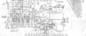
Kinematic diagram of a screw-cutting lathe 1B61
Kinematic diagram of a screw-cutting lathe 1B61
Bearing layout for screw-cutting lathe 1B61
Design of screw-cutting lathe 1B61
bed
The machine bed is installed on two pedestals and bolted to them. Between the pedestals there is a trough designed to drain coolant into the reservoir of the electric pump installed in the right pedestal. The electric motor of the main drive of the machine is mounted in the left cabinet. The bed has three isosceles prismatic and one flat guides. The caliper moves along two outer prisms, and the tailstock is installed on one (middle) prism with a flat guide.
Gearbox
Gearbox of screw-cutting lathe 1B61
The gearbox mechanism (Fig. 8) is enclosed in a cast iron housing, which is installed on the left side of the frame and bolted to it. The gearbox transmits 24 different speeds in the Range 10..1250 /1L6I/ and 16..2000 /1B61/. The spindle receives movement from an AL42/4 electric motor with a power of 2.8 kW /1L61/ and an A5I/4 with a power of 4.5 kW /1B61/, /see Fig. 6/.
Changing spindle speeds is achieved by moving blocks 1-2-3-4; 9-10-11 handle U1. In this case, 12 high speeds are obtained through the 19-22 gear, and 12 low speeds through the 16-17-18-19-20-21 gear.
The feed is transmitted from the spindle through the gearbox by gears 24-25, 27-29 to shaft VIII, or from shaft III and gear 23 to gear 26. The snaffle / gears 28-30/ is used to reverse the rotation of the lead screw when cutting left-hand threads, it is controlled handle U2.
The spindle and all shafts are mounted on rolling bearings. The front spindle journal is mounted on a double-row roller bearing, and the rear journal is mounted on an adjustable tapered bearing.
Sketch of the spindle cone in Fig. 4.
The spindle play is adjusted by tightening nut I, followed by locking it with a lock nut.
To eliminate radial play of the spindle when the front bearing is worn, tighten nut 2 /Fig.8/.
Gearbox /Guitar/
The gearbox is used to transmit movement from the gearbox to the feedbox mechanism and to adjust the feed to the type of thread being cut.
When cutting metric and inch threads, the movement is transmitted through gears 31-32-33-35. Gear ratio - 3. When cutting modular and pitch threads, the movement is transmitted through gears 31-32-34-33-36-35, gear ratio - 30/29. 41/36 /Fig.6/. Thus, the choice of thread type is achieved by turning the block 33-34 over.
Feed box for screw-cutting lathe 1B61
Feed boxes for screw-cutting lathe 1B61
The design of the feed box /Fig.9/ allows you to obtain a large number of different types of threads and feeds. The feed box is driven from the spindle and from the shaft of the III gearbox /with a feed rate increased by 16 times/. The movement from the feed box is transmitted to the lead shaft and lead screw /when cutting threads/.
Increased feeds are obtained only at low spindle speeds: for the 1L61 machine from 10 to 100 rpm, for the 1B61 machine from 16 to 160 rpm.
When cutting metric and modular threads, movement is transmitted to the lead screw: shaft XI through gear couplings 37a, 37b; gears 39, 40, 41, 42, 43,44, 45, 46, 47; gear couplings 48a and 48b and a multiplying mechanism /51-58/ to shaft XIV with gear 59 and through gear couplings 61a and 61 to lead screw XVII /Fig.6/.
When cutting inch and pitch threads, the movement of the lead screw is transmitted by gears 37-38, shaft XII, gears 39-47, 49-48 and a multiplying mechanism /51-58/. Further movement is transmitted in the same way as when cutting metric modular threads. In addition, the lead screw has direct activation when cutting particularly precise threads. This is achieved by appropriately adjusting the guitar's gears, which are available upon special order.
When the running roller is turned on, the movement is transmitted through gears 59-60 to the running shaft. The multiplier mechanism /gears 51-58/ gives the following gear ratios: 1/1, 1/2, 1/4, 1/8.
The choice of thread size is carried out using handle U4. Selecting the type of thread and turning on the lead screw or lead shaft is carried out using the U5 handle.
Direct activation of the lead screw is achieved by turning handle U5.
Apron for screw-cutting lathe 1B61
Apron for screw-cutting lathe 1B61
The apron /Fig. 10/ transmits movement to the caliper from the lead screw or lead roller. The feed of the caliper during turning is carried out exclusively with the help of a lead roller, while the lead screw is used only when cutting threads. For longitudinal movement of the caliper, the movement is transmitted /Fig. 6/ by the running shaft XIX, gear 62, cam gear 63 to shaft XX, worm 64 with worm wheel 65. Then the movement is transmitted to the rocker arm and gears 66-67-68-72-73-74 -on shaft XXV and gear 75 with rack 77.
To move the caliper transversely, the movement is transmitted along the same chain to the rocker arm, then through gears 66-67-72-80 to screw 82 with nut 81. Gear 69 on the rocker arm is used to reverse the movement of the caliper. To turn on the longitudinal feed of the caliper, handle U12 must be pulled out towards you and then turned to the right or left depending on the required direction of movement of the caliper /Fig. 17/. To turn on the lead screw, handle U12 should be pressed and turned clockwise. To turn on the transverse feed of the caliper, it is necessary to move the U13 handle to the upper position, having first placed the U12 handle in the neutral position, and then, with the handle extended to the fullest, tell the caliper the desired direction of movement. The U9 flywheel is used to move the apron manually. The apron has a locking device that prevents the simultaneous activation of the lead shaft and the lead screw.
The apron is equipped with a cam safety clutch, which protects the feed mechanism from overload. The coupling is adjusted separately for transverse and longitudinal feeds using screw I /Fig. 10/.
When the lead screw is operating, it is necessary to remove the rack gear 75 from engagement with the rack 77 using handle U10 /Fig.6/.
Caliper
The caliper has a conventional cross design /Fig. 11/ Longitudinal movement of the caliper is carried out mechanically using a roller or lead screw /exclusively for threads/ and manually by rotating the flywheel located on the apron.
The upper part of the support, which carries a square cutting head, can only be moved by hand using a handle and a screw 86 with a nut 85 /Fig.6/.
The clearance of the caliper guides is adjusted by tightening the corresponding wedges 1 and 2.
The backlash is selected with nuts 4.5, 6 and screw 3 /Fig. 11/.
Tailstock
The tailstock /Fig. 12/ moves along the frame by hand along the guides and is secured in the required position with handle U18 /Fig. 17/. Transverse movement of the headstock within ± 12 is carried out using a screw. Axial movement of the quill occurs when the flywheel rotates; the quill is secured with handle U17. The flywheel and screw serve at the same time to push the center out of its socket. The tailstock can move along with the movement of the carriage using a special device located on it and the support. The backlash of the tailstock screw is adjusted by a nut with a lock nut /Fig. 12/.
General layout and features of the VSN tabletop drilling machine
Machine bed
The bed is also a machine table on which machine vices are installed and secured to secure workpieces.
Column
The column is a cylindrical stand with an external cylindrical thread on which the spindle head is mounted. The spindle head rises and falls along the column with the help of a nut on which it rests. After installing the spindle headstock to the desired height, the headstock is clamped onto the column.
Headstock
The spindle head is based on a cast iron body. Mounted in the housing:
- Spindle unit
- Headstock lifting mechanism
- Headstock clamping mechanism
- Belt tension mechanism
- Local machine lighting
An electric motor is attached to the back of the headstock.
The headstock lifting mechanism is designed to move the spindle headstock along the column.
The column is attached to the plate with a bracket. The column is clamped in the bracket with two bolts. If it is necessary to rotate the column around its axis, the bolts are released, the column together with the headstock is rotated to the required position, after which the bolts are clamped.
Spindle assembly of the VSN tabletop drilling machine
spindle is a multi-stage shaft made of high-quality steel. The spindle is an expensive and difficult part to manufacture
The lower end of the spindle is an outer Morse cone KM2, designation B18 according to GOST 9953 (Shortened tool cones) - shortened cone: D = 17.780 mm, cone length 37.0 mm.
The upper end of the spindle is a splined shaft on which the receiving pulley of the belt drive is mounted, from which it receives rotation.
The spindle supports are rolling bearings that absorb radial and axial loads from cutting forces. The front spindle support is especially accurate and reliable, since it absorbs the bulk of the load and transfers directly to the workpiece all the errors of its installation. Angular contact ball bearings are often used as the front support of spindles of drilling machines, which absorb radial and axial loads. This bearing has greater performance, rigidity, and high speed.
The spindle is mounted in a steel sleeve - quills. The quill moves vertically 100 mm inside the spindle head along with the rotating spindle.
Moving (feeding) the quill is manual; carried out by rotating the steering wheel on the axis of which the gear is.
VSN machine drive
The electric motor is attached to the spindle head by means of a submotor plate. On the axis of the electric motor there is a stepped pulley, which is connected to the spindle pulley by a V-belt.
Local lighting of the VSN machine
The machine is equipped with equipment for local lighting. Due to the fact that a table-top drilling machine, model VSN, is most often installed on workbenches or tables, therefore, the fittings (bracket) and the apparatus (transformer) for local lighting, when installing the machine, must be attached near the machine, and if the machine is installed against a wall - then to the last one.
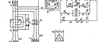
Electrical equipment. Electrical diagram of a screw-cutting lathe 1B61
Electrical diagram of a screw-cutting lathe 1B61
- Connection to a three-phase alternating current network with a voltage of 380 V
- Main drive motor:
- for machine 1B61 - A5I-4; 4.5 kW; 1440 rpm, 380/220 V;
- for machine 1L61 - AL42/4; 2.8 kW; 1420 rpm, 380/220 V.
- Electric coolant pump: 0.125 kW, 2800 rpm, 22 lit/min, 380/220 V.
- Starting, shutting down, changing the direction of the main movement is carried out by means of a reversible magnetic starter, controlled by a drum switch using two control handles U20 /Fig. 17/.
- Braking of the main drive motor is done using an electromagnetic clutch.
- Quick reversal of the electric motor when cutting threads - by turning handle U20 from the upper extreme position to the lower extreme position and vice versa.
- Switching the electric pump on and off using a separate switch.
- Protection of the main drive motor and electric pump from short circuits by means of fuses.
- Zero protection of the main drive motor - via an intermediate relay.
- Local lighting - from a step-down transformer.
- Protective grounding of metal masses as a safety measure for those working on the machine.
- Control panel with handles for the main switch, electric pump and local lighting.
b/ Description of the operation of the electrical control circuit /Fig. 14/
By turning on the input switch BB, the machine is prepared to start. Starting, stopping and reversing the main drive engine /GD/ is carried out using the control handle of the KK command controller, which has 3 fixed positions and one contact for each position, of which the KKO contact /L 22-1/ is closed in the neutral position. After turning on the BB switch through the NC contact KKO, the intermediate relay RP receives power and closes its NO contact /L 22-1/. Through the NO contact RP /L 22-1/ the intermediate relay RP switches to self-supply.
After switching on, the explosive receives power and the time relay RV, the contact of which RV /12-13/ with a time delay / 3..4 sec / will turn off the electromagnetic clutch EMT. When starting in the “Forward” direction (rotation of the main engine is counterclockwise from the pulley side), handle 20 must be turned up. The closed contact KKV /1-2/ closes the circuit of the KB coil, a circuit is formed /L 22-1 - 1-2 -L82/, the KB contactor is triggered by its NO contact, turns on the motor in the direction of rotation “Forward” and the NC contact of the KB contactor /1-4/ opens. The time relay PB loses power, the contact PB /10-12/ opens and the contact PB /12-13/ closes. The “Forward” activation process is completed. The engine is turned off by moving handle U20 to the neutral position. In this case, the KKV contact opens, the KB contactor is de-energized, and closes its H3 contact at points 1-4. The time relay PB, receiving power, closes the NO contact PB /10-12/ without a time delay. Through selenium rectifiers BC, the electromagnetic clutch EMT receives direct current, operates and brakes the gearbox and spindle mechanism.
Somewhat later, with a time delay /3..4 sec/, the PB contact /12-13/ opens, the electromagnetic clutch is turned off, and the circuit is returned to its original position. The “Back” start is performed by moving the U20 handle to the lower position. The operation of the circuit is similar to the “Forward” operation, only in this case the KN contactor is activated. The local lighting transformer TO is turned on and off by the VO switch. The electric pump is turned on and off by the VE package switch.
c/ Protection and blocking
The circuit provides group protection against short circuits using 1P fuses.
The circuit provides protection against voltage failure /zero/ by means of an intermediate relay RP.
To prevent the simultaneous activation of two contactors of the reversing starter KB and KN, a mechanical interlock is provided in the circuit.
The wiring diagram is shown in Fig. 15. Location of electrical devices in Fig. 16.
Design features
According to its technical characteristics, the 1M61 lathe is assigned to the “N” accuracy class. The electric motor of the unit is capable of operating in a reversible range. The spindle rotation speed is comparable to the possibility of changing the functioning of the gearbox and aggregating diverse gears with each other.
The unit in question can use cutters, drills and taps of various configurations. Such universalization allows you to perform a whole range of technological manipulations, including external turning, reaming, drilling, cutting and similar operations.
Transverse and longitudinal movements are made using a roller and a screw; a flywheel is located on its front part. The lead screw is used when cutting threads; the parameters of the apron make it possible to block the aggregation of caliper movements. This eliminates the risk of moving the caliper with the roller and screw.
Technical characteristics of the machine 1B61
| Parameter name | 1L61 | 1B61 | 1B61 | 1M61 |
| Main settings | ||||
| Accuracy class according to GOST 8-82 | N | N | N | N |
| The largest diameter of the workpiece installed above the bed, mm | 320 | 320 | 320 | 320 |
| The largest diameter of the workpiece processed above the support, mm | 160 | 160 | 160 | 160 |
| Maximum workpiece length (RMC), mm | 500 | 710, 1000 | 500, 710 | 710, 1000 |
| Maximum turning length (Maximum longitudinal movement of the support), mm | 430 | 640, 930 | 430, 640 | 640 |
| Center height, mm | 170 | 170 | 170 | 170 |
| The greatest distance from the center axis to the edge of the tool holder, mm | 190 | 190 | 180 | 180 |
| Height from the cutting surface to the spindle axis, mm | 25 | 25 | 25 | 25 |
| The largest cross-sectional dimensions of the cutter holder (width x height), mm | 22 x 35 | 22 x 35 | 22 x 35 | 22 x 25 |
| Spindle | ||||
| Diameter of through hole in spindle, mm | 35 | 35 | 35 | 35 |
| The largest diameter of the rod passing through the hole in the spindle mm | 32 | 32 | 32 | 32 |
| Number of frequency steps for forward and reverse rotation of the spindle | 24 | 24 | 8 | 24 |
| Spindle forward and reverse rotation frequency, rpm | 10..1250 | 16..2000 | 32..1200 | 12,5..1600 |
| The size of the internal cone in the spindle according to GOST 13214-67 | M5 | M5 | M5 | M5 |
| Spindle end according to GOST 12593-72 | M75 x 5 | M75 x 5 | 6K | 6K |
| Spindle braking | There is | There is | There is | There is |
| Caliper. Submissions | ||||
| Maximum longitudinal movement of the caliper carriage, mm | 430 | 640, 930 | 600 | 640 |
| Maximum lateral movement of the caliper, mm | 250 | 250 | 200 | 200 |
| Longitudinal movement of the caliper per dial division, mm | 0,5 | 0,5 | 0,5 | 0,5 |
| Longitudinal movement of the caliper per one revolution of the dial, mm | 100 | 100 | 100 | 100 |
| Transverse movement of the caliper per dial division, mm | 0,05 | 0,05 | 0,05 | 0,05 |
| Transverse movement of the caliper per one revolution of the dial, mm | 5 | 5 | 5 | 5 |
| Number of stages of longitudinal and transverse feeds | 17 | |||
| Limits of longitudinal feed speed, mm/rev | 0,08..1,2 | 0,08..1,2 0,12..1,9 | ||
| Transverse feed speed limits, mm/rev | 0,04..0,6 | 0,04..0,6 0,06..0,95 | ||
| Speed of fast movements of the caliper, longitudinal/transverse, m/min | No | No | No | No |
| Number of metric threads to be cut | 13 | |||
| Limits of pitches of cut metric threads, mm | 0,5..96 | 0,5..96 | 0,5..96 | 0,5..6 |
| Number of inch threads to be cut | 16 | |||
| Limits of pitches of cut inch threads | 0,25…48 | 0,25…48 | 0,25…48 | 3,5…48 |
| Number of modular threads to be cut | 10 | |||
| Limits of pitches of cut modular threads | 0,25…48 | 0,25…48 | 0,25…48 | 0,25…3 |
| Number of cut pitch threads | 16 | |||
| Limits of pitches of cut pitch threads | 0,5..96 | 0,5..96 | 0,5..96 | 7…96 |
| Overload fuse | ||||
| Blocking longitudinal and transverse feeds | ||||
| Switching longitudinal stops | ||||
| Cutting slide (Upper slide) | ||||
| Maximum movement of the upper support (cutting slide), mm | 125 | 125 | 125 | 120 |
| The price of division of the upper support limb (cutting slide), mm | 0,03 | 0,03 | 0,05 | 0,05 |
| Movement per one revolution of the dial, mm | 3 | 3 | ||
| Maximum rotation angle, degrees | ±60° | ±60° | ±60° | -60°, +45° |
| Tailstock | ||||
| Maximum movement of the tailstock quill, mm | 120 | 120 | 120 | 100 |
| Maximum movement of the tailstock, mm | ±12 | ±12 | ±12 | ±12 |
| Center in tailstock quill | Morse 4 | Morse 4 | Morse 4 | Morse 4 |
| Electrical equipment | ||||
| Number of electric motors on the machine | 2 | 2 | 2 | 2 |
| Main drive electric motor, kW (rpm) | 2,8 (1420) | 4,5 (1440) | 2,2 (1430) | 4,0 (1450) |
| Cooling pump electric motor, kW (rpm) | 0,12 (2800) | 0,12 (2800) | 0,12 (2800) | 0,12 (2800) |
| Self-centering 3-jaw chuck | ||||
| Chuck diameter, mm | Ø 200 | Ø 200 | Ø 200 | Ø 200, 7100-0007 |
| Diameter of adapter flange, mm | Ø 200 | Ø 200 | ||
| Weight, kg | 16,2 | 16,2 | ||
| Clamp diameter | 6..45 | 6..45 | ||
| Dimensions and weight of the machine | ||||
| Machine dimensions (length width height), mm | 1880 x 850 x 1450 | 2380 x 850 x 1450 | 1880 x 800 x 1450 | 2055 x 1095 x 1450 |
| Machine weight, kg | 1100 | 1600 (RMC=1000) | 1200 | 1260 |
- Screw-cutting lathes 1L61 and 1B61. Manual for machine tools, 1962
- Acherkan N.S. Metal-cutting machines, Volume 1, 1965
- Batov V.P. Lathes., 1978
- Beletsky D.G. Handbook of a universal turner, 1987
- Denezhny P.M., Stiskin G.M., Thor I.E. Turning, 1972. (1k62)
- Denezhny P.M., Stiskin G.M., Thor I.E. Turning, 1979. (16k20)
- Modzelevsky A. A., Muschinkin A. A., Kedrov S. S., Sobol A. M., Zavgorodniy Yu. P., Lathes, 1973
- Pikus M.Yu. A mechanic's guide to machine repair, 1987
- Skhirtladze A.G., Novikov V.Yu. Technological equipment for machine-building industries, 1980
- Tepinkichiev V.K. Metal cutting machines, 1973
- Chernov N.N. Metal cutting machines, 1988
Bibliography:
Related Links. Additional Information
Home About the company News Articles Price list Contacts Reference information Interesting video KPO woodworking machines Manufacturers