The lathe was invented many centuries ago. And since then, the principle of operation of this device has remained unchanged - the object being processed rotates, while simultaneously being modified to a given size. But the designs of lathes have undergone significant changes - now there is a wide variety of types of these devices.
Modern industry actively uses lathes for a variety of jobs:
- reaming holes (countersinking);
- turning and boring planes of various types (cylindrical, shaped or conical);
- drilling;
- processing the end edges of products, trimming the ends;
- thread cutting.
Information about the manufacturer of the screw-cutting lathe 16М05А
The manufacturer of the 16M05A screw-cutting lathe was the Odessa Machine Tool Plant .
Machine tools produced by the Odessa Machine Tool Plant (OSZ) and the Experimental Mechanical Plant (OMZ)
- 1P611
- high-precision screw-cutting lathe, Ø 250 - 16B05A
- especially high precision screw-cutting lathe, Ø 250 - 16B05P
- high-precision screw-cutting lathe, Ø 250, Kirovakan - 16M05A
- screw-cutting lathe of especially high precision, Ø 250 - 1601
— table lathe Ø 125 - 1604
— high-precision screw-cutting lathe, Ø 200 - 1613D
- precision screw-cutting lathe, Ø 240 x 270 - OT-4
- lightweight high-precision screw-cutting lathe, Ø 250 - OT-5
- high-precision, lightweight lathe-screw-cutting machine, Ø 250
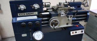
16M05A screw-cutting lathe of particularly high precision. Purpose, scope
An especially high-precision screw-cutting lathe, model 16M05A , with a maximum processing diameter of 250 mm over the bed, is designed to perform various high-precision turning operations performed on centers, collets, chucks and faceplates, as well as for cutting metric, inch and modular threads.
The turning machine model 16М05А ensures high-class quality of the processed surface and work accuracy (accuracy of dimensions and geometric shapes).
It is used in enterprises of the instrument-making, radio engineering, tool industries and precision engineering.
The especially high-precision screw-cutting lathe 16M05A is manufactured on the basis of the high-precision screw-cutting lathe 16B04P.
Main design features. Installation of the variator on a special plate that does not have contact with the stand, as well as the independent suspension of the machine apron, reduces the level of vibration during processing and improves the quality of the machined surface.
The feed box provides the ability to cut a large number of metric, modular threads and obtain a wide range of longitudinal and transverse feeds without changing guitar gears. The spindle is mounted in original radial and thrust hydrostatic bearings, which, combined with the rigid design of the machine, allows for unique turning precision.
The machine is intended for use in climatic conditions UHL4.1 according to GOST 15150-69.
It is not built into an automatic line.
The accuracy class of the machine is A according to GOST 8-82E (especially high accuracy).
Developer: Odessa Design Bureau of Special Machine Tools.
Manufacturer: Odessa Machine Tool Plant.
Lathe designation
1
— lathe (group number according to ENIMS classification)
6
– subgroup number (1, 2, 3, 4, 5, 6, 7, 8, 9) according to the ENIMS classification (6 - screw-cutting lathe)
M
– generation of the machine (A, B, C, D, K, L, M, R) or designation of the manufacturer
05
– height of centers above the bed
Letters at the end of the model designation:
G
– version of the machine with a recess in the bed
TO
– version of the machine with a hydrocopier
M
– design of the machine for mass production with a hydrocopier
P
– design of the machine with increased accuracy according to GOST 8-82
IN
– design of the machine with high accuracy according to GOST 8-82
F1
– version of the machine with a digital display device DRO
F3
– machine version with CNC system
Why is it necessary in everyday life?
We can say that home lathes are small copies of professional ones, which makes it easy to learn the specifics of working on it and the processing process itself.
A home lathe, of course, does not have the dimensions and technical features of professional equipment used in large workshops and industries. But with the help of this device you can easily carry out all the necessary work on processing external/internal surfaces, cutting threads, carrying out milling operations and drilling.
For work in a home workshop, small-sized machines are usually used, which have less power and options. But the quality of the products does not change and remains at a high level.
The main advantages of a home metal cutting machine are:
Affordable price. Thanks to the low price, many people can afford the necessary household items.- Reduced noise and vibration levels.
- Increased device rigidity.
- Ease of operation and further maintenance of the machine.
- The presence of already polished beds (they are fixed on the machine in a certain way).
- Excellent processing accuracy. This is achieved through the use of precision roller bearings in the design.
After purchasing such a device, the owner no longer has to think about who to contact to manufacture or process the necessary part. This increases the return on investment of the machine, since you will not need to contact service centers, workshops or factories.
Having become the owner of a home metal processing machine, the owner may not even remember problems such as:
- difficulties when forming threads with different pitches (internal or external);
- difficulties with turning an object to the specified size and shape;
- the question of where to bore the blanks;
- trim the side edges of the product;
- drill holes, connectors of various diameters;
- Carefully trim off excess iron elements.
Expert opinion
Levin Dmitry Konstantinovich
Using a home lathe, you can make a product that is ideal in size, shape and quality, practically indistinguishable from a factory one.
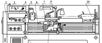
16М05А Arrangement of components of a screw-cutting lathe
Arrangement of components of screw-cutting lathe 16m05a
List of components of screw-cutting lathe 16М05А
- Bed – 16M05A.111.000
- Cabinet - 16M05A.121.000
- Front headstock - 16M05A .221.000
- Guitar – 16M05A.311.000
- Caliper - 16М05А.341.000
- Hydrostatic unit - 16М05A.071.000
- Hydrocommunications - 16M05A.721.000
- Electrical equipment of the machine - 16М05А.811.000
- Cooling - 16B04P.511.000
- Fencing - 16B04P.611.000
- CVT - 16B05A.212.000
- Rear headstock - 16B05A.231.000
- Feed box - 16B05A.321.000
- Apron - 16B03A.331.000
- Shield* - 16B05A.621.000
- Switch - 16B05A.822.000
16М05А Location of controls for a screw-cutting lathe
Location of controls for screw-cutting lathe 16m05a
List of controls for screw-cutting lathe 16М05А
- 1. Upper carriage clamp screw
- 2. Caliper rotary clamp screw
- 3. Signal lamp “Filter clogged”
- 4. Warning lamp “Axial spindle overload”
- 5. Signal lamp “Hydrostatics on”
- 6. Signal lamp “Network”
- 7. Button “Start hydrostatics”
- 8. “All stop” button
- 9. “Collet release” button
- 10. “Collet Clamp” button
- 11. Feed and thread reverse handle
- 12. Thread pitch increasing link handle
- 13. Shift knob
- 14. Handle for switching feeds and threads
- 15. Feed and thread switching handle
- 16. Handle for switching feeds and threads
- 17. Feed and thread switching handle
- 18. Handle for turning on the lead screw or roller
- 20. CVT control handle
- 21. Finish feed reverse handle
- 23. Flywheel for manual longitudinal movement of the caliper
- 24. Handwheel for changing spindle speed
- 25. Handle for turning on forward and reverse rotation of the spindle and braking
- 31. Power on/off handle
- 33. Cooling switch
- 35. Button for turning on the handwheel and longitudinal feed dial
- 36. Safety device activation handle
- 38. Button for switching longitudinal and transverse feed of the caliper
- 39. Traction adjustment knob
- 42. Handle for turning on the uterine nut
- 43. Handle for manual transverse movement
- 44. Screw clamping the caliper on the frame
- 45. Tailstock lateral offset screw
- 46. Handle for moving the upper carriage
- 47. Handwheel for moving the tailstock quill
- 48. Tailstock quill clamp handle
- 49. Tailstock clamp handle
- 50. Coolant supply valve
- 51. Cooling pipe clamp handle
- 52. Tool holder clamp handle
- 53. Handle clamp guard terminal
- 54. Light switch
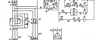
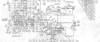
16М05А Kinematic diagram of a screw-cutting lathe
Kinematic diagram of a screw-cutting lathe 16m05a
The kinematic diagram of the machine allows the following operations:
- spindle rotation - main movement drive
- movement of the cutter - drive of threads and normal feeds, drive of fine feeds
- rotation of the lubrication pump
Main drive
Electric motor 1, using clutch 2, rotates shaft 1 with the drive pulley of the variator 3. Rotation from the drive pulley to the driven pulley 4 is transmitted by a wide V-belt. The change in the rotation speed of driven shaft II is ensured by changing the working diameters of the variator pulleys when moving the controlled part of the driven pulley and the corresponding movement of the spring-loaded part of the drive pulley.
Rotation is transmitted to shaft III and pulley 9 using a toothed block 5, 7 and gears 6, 8. Pulley 9 is connected to pulley 17 by V-belts. Rotation from sleeve V is transmitted to spindle VII either directly when clutch 22 is engaged, or through a gear consisting of a gear 18 connected to sleeve V, gears 19, 20 mounted on shaft VI, and a gear 21 mounted on the spindle.
Drive of threads and normal feeds
When cutting threads, rotation from spindle VII is transmitted to shaft VIII using gears 23, 24 or, when the search is turned on (gears 18, 19, 20, 21), using gears 18,24.
Shaft IX receives rotation in the forward direction using gears 25, 27, in the opposite direction using gears 25, 26, 27. Replaceable guitar gears a, b, c, d transmit rotation to shaft XI of the feed box. The feed box contains the following mechanisms:
- mechanism for shifting a number of gears 30, 31, 32, 33
- main row mechanism - gears 33, 34, 31, 35, 36, 37, 38, 39
- multiplying mechanism - gears 40, 42, 43,45, 51, 44, 46
After these mechanisms, rotation is transmitted either to the lead screw 81 for cutting threads when the jaw clutch on the gear wheel 47 and on the XVI shaft is disconnected, or to the lead shaft XIX using gears 47, 48, 49, 51.
From the running roller, rotation is transmitted via clutch 54 to the worm 55 of the machine apron. Next, rotation is transmitted to shaft XXI using a worm wheel 56, a planetary gearbox consisting of gears 57, 58, 59, 60 and gears 61, 62. From shaft XXI, rotation is transmitted either to the rack and pinion gear 65 using gears 63,64 (longitudinal movement of the cutter), or to the screw 83 using gears 62, 70 (transverse movement of the cutter)
Fine feed drive
The rotation of the feedbox mechanism is transmitted from shaft III of the variator using gears 10, 11, V-belt transmission, pulleys 12, 28, to the XXV feedbox shaft and then gear 28 transmits rotation to gear 33 of the mechanism for changing the pitch of the feedbox.
Changing the direction of longitudinal or transverse feed is ensured by transmitting rotation to the running shaft XIX from the feed box shaft XV through a snaffle consisting of gears 49, 50, 51 when gear 49 is switched.
Planetary mechanism
Gears 13, 14, 15, 16 form a planetary mechanism, which provides rotation of the spindle speed reading scale when reconfiguring the variator rotation speed.
Types of machines Comment
Milling machines
On milling machines, you can process external and internal surfaces of various configurations, cut straight and helical grooves, cut external and internal threads, process gears, etc.
The machines are distinguished:
- cantilever-milling (horizontal, vertical, universal and wide-universal)
- vertical milling non-cantilever,
- longitudinal milling (one- and two-column),
- continuous milling machines (rotary and drum),
- copy milling (for contour and volumetric milling),
- engraving and milling,
- specialized (thread milling, key-milling, slot milling, etc.).
Modern milling machines use separate drives for the main movement and feeds, mechanisms for accelerated table movements (in all directions), and single-handle control for changing the feed speed. In machine tools, components and parts are widely unified. Machines are called cantilever machines because the machine table is mounted on a console that moves upward along the guides of the bed.
Cantilever milling machines include horizontal milling, vertical milling, universal and wide-universal. The main size of general purpose milling machines is the size of the working surface of the table. In horizontal cantilever milling machines, the spindle axis is located horizontally, and the table moves in three mutually perpendicular directions.
Universal cantilever milling machines outwardly almost do not differ from horizontal machines, but they have a rotary table, which, in addition to the ability to move in three mutually perpendicular directions, can be rotated around its vertical axis by ±45º. This allows you to machine helical grooves and cut helical wheels.
Vertical cantilever milling machines differ in appearance from horizontal ones in the vertical location of the spindle axis and the absence of a trunk. The trunk of horizontal machines serves to secure the bracket that supports the end of the milling mandrel.
Widely universal cantilever milling machines, unlike universal ones, have an additional spindle that rotates around the vertical and horizontal axes. There are also widely universal machines with two spindles (horizontal and vertical) and a table that rotates around its axis. In universal milling machines, the spindle can be installed at any angle to the workpiece being processed.
Horizontal, vertical and universal milling machines
Continuous milling machines
When working on continuous milling machines, workpieces are placed and secured on tables without stopping movement. The productivity of such machines is high; they are used in large-scale and mass production.
Continuous milling machines are divided into rotary and drum. On a rotary machine, the workpieces are installed in fixtures on a rotating table, then they are passed to remove the allowance under one or two cutters and removed from the table. A part processing cycle can be completed in just a few table revolutions.
A drum machine for continuous operation is used for processing relatively large workpieces simultaneously on both sides. The workpiece is secured in devices that are installed on the periphery of a slowly rotating massive drum. Processing is carried out using cutters. Workpieces are installed and parts are removed while the machine is operating from the side opposite to the cutter.
Dividing heads
Dividing heads are used when working on cantilever milling machines to set the workpiece at the required angle relative to the machine table, rotate it at a certain angle, divide the circle into the required number of parts, and also for continuous rotation of the workpiece when milling helical grooves. There are dividing heads for direct division (dividing devices), optical dividing heads and universal dividing heads. Universal dividing heads are divided into limb and limbless. The most common are dial heads. Universal dividing heads can be used for simple and differentiated division.
Capabilities of screw-cutting lathes
Capabilities of screw-cutting lathe 16m05a
The photograph shows a steel ball that has been completely machined on a lathe.
From a solid workpiece, using a set of tools, it is possible to turn a ball in a ball , a cube in a cube in a cube and in a cube , a cube in a dodecahedron , which in turn is in a ball, a ring in a ring .
Lathes - high quality and modern technology!
The history of lathes goes back several centuries, and since their invention the principle of operation has remained the same - processing parts (rotation bodies) with cutting tools (cutters). The workpiece is clamped in the main unit of the machine - the spindle, and rotates with it at high speed. The cutters move relative to the body of rotation in two directions - parallel and across the central axis, removing chips and giving the part the desired shape. In this way, all basic turning operations can be carried out: trimming, drilling, grinding, threading, etc. The more massive the spindle and the higher the speed of its rotation, the greater the productivity of the lathe
. The most powerful machines can grind workpieces weighing several tons, but for basic tasks the capabilities of conventional, low-power machines presented in our catalog are quite sufficient.
Main technical characteristics of the machine 16М05А
| Parameter name | 16M05A | 16B05A |
| Basic machine parameters | ||
| Accuracy class | A | A |
| The largest diameter of the workpiece processed above the bed, mm | 250 | 250 |
| The largest diameter of the workpiece installed above the bed, mm | 270 | |
| The largest diameter of the workpiece installed above the caliper, mm | 139 | 145 |
| Maximum length of the workpiece at centers (RMC), mm | 500 | 500 |
| Height of centers above flat bed guides, mm | 135 | 135 |
| The greatest distance from the axis of the centers to the edge of the tool holder, mm | 135 | 135 |
| Diameter of the workpiece installed in the chuck, mm | 5..160 | |
| Diameter of the workpiece installed in the collet, mm | 4..28 | |
| Diameter of the workpiece installed in the steady rest, mm | 5..50 | |
| Sample processing accuracy indicators: roundness, microns | 1,2 | |
| Roughness indicators for processing non-ferrous metal samples, microns | 0,04 | |
| Roughness indicators for processing steel samples, microns | 0,63 | |
| Productivity increase factor compared to the machine model 16B05A | 1,2 | |
| Spindle | ||
| Spindle hole diameter, mm | 32 | 26,5 |
| The largest diameter of the rod passing through the hole in the spindle, mm | 26 | |
| Spindle center according to GOST 13214-67 | Morse 5 | Morse 4 |
| Spindle end according to GOST 12593-72 | 4K | 4K |
| Number of speed steps for direct spindle rotation | b/s regulation | b/s regulation |
| Spindle direct rotation frequency, rpm | 25..2500 | 25..2500 |
| Spindle braking | There is | There is |
| Handle lock | ||
| Caliper. Submissions | ||
| Maximum longitudinal movement of the caliper, mm | 520 | 520 |
| Maximum lateral movement of the caliper, mm | 160 | 160 |
| Transverse movement of the caliper by one division of the dial, mm | 0,02 | 0,02 |
| Number of longitudinal feeds of the caliper | 28 | 28 |
| Number of cross feeds | 28 | 28 |
| Limits of longitudinal caliper feeds (in brackets - when using a pitch increasing link), mm/rev | 0,01..0,35 (0,01..2,8) | 0,01..0,35 (0,01..2,8) |
| Transverse caliper feed limits (in parentheses - when using a pitch increasing link), mm/rev | 0,005..0,175 (0,005..1,4) | 0,005..0,175 (0,005..1,4) |
| Steps of cut metric threads, mm | 0,2..28 | 0,2..28 |
| Steps of cut modular threads, mod | 0,1..14 | 0,1..14 |
| Steps of cut inch threads, threads per inch | 5..96 | 5..96 |
| Speed of rapid movements, mm/min | No | No |
| Cutting slide | ||
| Maximum length of movement of the cutting slide, mm | 150 | 150 |
| Movement of the cutting slide by one division of the dial, mm | 0,02 | 0,02 |
| Maximum angle of rotation of the cutting slide, degrees | ±45° | ±45° |
| Scale division of the tool slide rotation scale, deg | 1° | 1° |
| The largest cross-section of the cutter holder, mm | 16 x 16 | 16 x 16 |
| Height from the supporting surface of the cutter to the axis of the centers (cutter height), mm | 16 | 16 |
| Number of cutters in the cutting head | 4 | 4 |
| Tailstock | ||
| Quill diameter, mm | ||
| Tailstock quill hole cone according to GOST 2847-67 | Morse 3 | Morse 3 |
| Maximum movement of the quill, mm | 85 | 85 |
| Movement of the quill by one division of the dial, mm | 0,02 | 0,02 |
| Moving the quill by one ruler, mm | 1 | 1 |
| The amount of lateral displacement of the headstock body, mm | ±10 | ±10 |
| Electrical equipment | ||
| Number of electric motors installed on the machine | 3 | 3 |
| Main drive electric motor, kW | 1,5 | 1,5 |
| Hydraulic pump electric motor, kW | 2,2 | 0,75 |
| Coolant pump electric motor, kW | 0,12 | 0,12 |
| Total power of electric motors installed on the machine, kW | 3,82 | 2,37 |
| Dimensions and weight of the machine | ||
| Machine dimensions (length width height), mm | 1550 x 1350 x 1400 | 1530 x 910 x 1385 |
| Machine weight, kg | 1400 | 1365 |
- Extra high precision screw-cutting lathe 16M05A. Operating manual 16М05А.000.000 RE, 1989
- Acherkan N.S. Metal-cutting machines, Volume 1, 1965
- Batov V.P. Lathes, 1978
- Beletsky D.G. Handbook of a universal turner, 1987
- Denezhny P.M., Stiskin G.M., Thor I.E. Turning, 1972. (1k62)
- Denezhny P.M., Stiskin G.M., Thor I.E. Turning, 1979. (16k20)
- Modzelevsky A. A., Muschinkin A. A., Kedrov S. S., Sobol A. M., Zavgorodniy Yu. P., Lathes, 1973
- Pikus M.Yu. A mechanic's guide to machine repair, 1987
- Skhirtladze A.G., Novikov V.Yu. Technological equipment for machine-building industries, 1980
- Tepinkichiev V.K. Metal cutting machines, 1973
- Chernov N.N. Metal cutting machines, 1988
Bibliography:
Related Links. Additional Information
- Classification and main characteristics of turning
- Selecting the right metalworking machine
- Multi-start thread. Methods for cutting multi-start threads on a lathe
- Graphic signs for lathes
- Friction clutch of a screw-cutting lathe
- Methodology for checking and testing screw-cutting lathes for accuracy
- Directory of lathe manufacturing plants
- Directory of lathes
Home About the company News Articles Price list Contacts Reference information Interesting video KPO woodworking machines Manufacturers
How to choose an option for your home
A well-chosen home lathe will also be useful when servicing a vehicle and will significantly simplify the tasks of caring for your garden plot.
If you have such equipment, you can always grind any necessary part for repair. To avoid making a mistake when choosing a home machine, consider the following nuances:
- Budget . Often, for home use, purchase a basic model. And various additional functionality is equipped as needed.
- Quality . Before making a purchase, carefully inspect the model for possible damage. And do not make such transactions online (for ordering and delivery). After all, in this case there will be no opportunity to touch, look and check the machine.
- Varieties . The choice of a home lathe depends on the purpose of its further use.
Expert opinion
Levin Dmitry Konstantinovich
If your financial capabilities allow, it is better to buy a universal machine that has a large range of functions.
According to their purpose, all such models are divided into 4 main types:
- Tabletop . They are distinguished by their compact size and low weight. The smallest model will weigh about 10-12 kg. This type of machine is designed for processing small parts and operations: trimming edges, grinding, widening or making new holes, turning parts, threading them, etc.
- Universal . Designed to perform several functions at once. The differences are the increased diameter of the workpiece and the increased distance between the two rotating centers. Universal type machines are easy to maintain and easy to use.
- Lathe-screw . These models are especially popular. After all, with their help you can process almost any product, even weighing 10 tons, and the center distance can vary within 7-8 m.
- School . The simplest devices in terms of functionality that anyone can use. These models are capable of processing almost any part, regardless of shape. With their help you can easily cut threads, make holes and give the object the desired shape. And, if necessary, sharpen, polish or roll up household tools. And by purchasing additional equipment, you can significantly expand the capabilities of the device and make the machine suitable for milling or cutting teeth. Such models are small-sized and compact.
School lathes are capable of working not only on metal. With their help you can easily process wood and plastic.
But remember that machines intended for home use are still not as advanced as professional ones. The main inconvenience is the time that has to be spent on processing. But all shortcomings are covered by the guaranteed high quality of the final result.