Classification
The range of steel water pipes includes seamless and welded pipes, galvanized and without anti-corrosion coating.
The main characteristic of any pipe is its diameter. In the case of water pipes, the internal diameter of the pipe (its clearance) is more important; external depends on the thickness of the walls and affects the pipe’s ability to withstand external mechanical influences, its wear life and how much water pressure it can withstand without deformation and rupture.
The throughput of water pipes depends linearly on their internal diameter. In addition to the diameter, of course, other factors also influence the permeability of the pipe: the number and angle of pipe bends, the roughness of the inner surface, and the presence of shut-off valves.
The range of water pipes made of metal-plastic and polypropylene, used to create water supply systems in houses and apartments, includes pipes with a diameter of 16 to 40 mm.
Of course, most manufacturers also offer pipes of larger diameter, but they are practically not used in intra-house lines for three reasons:
- Installation of large-diameter pipes becomes extremely labor-intensive. If the diameter of the metal-plastic pipe is more than 50 mm, the union nut on the fitting will have to be tightened with a wrench of at least number five.
- Since pipes made from modern materials do not reduce patency over time, there is no need to make adjustments for subsequent narrowing of the lumen.
- The smooth inner surface creates minimal resistance to water movement. If so, for any reasonable water consumption, even in an apartment building, a larger diameter is simply not needed.
There is nothing here to create resistance to the flow of water
So, to summarize: the characteristics of water pipes that are important in practical terms are the physical properties of the pipe (arising from the material it is made of) and its diameter.
Key material
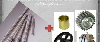
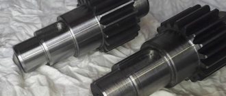
For the manufacture of keyed joints, calibrated rolled metal is used. The most commonly used steel is grade 45. It is a regular type of carbon steel, which is often used to produce high-strength parts. The steel is used in the form of a 1 m long bar.
In some cases, carbon steel grade 50 can be used. It is necessary when increased strength properties of the resulting keys are required. Less commonly used are alloy steels, for example, grade 40x, which is characterized by a high hardness index achieved by heat treatment.
Steel blanks are processed using cutters, drilling machines, chopping machines, grinders and other tools. The machines used have a control unit that allows, using numerical programs, to produce a part with the required parameters.
The price of the resulting key is quite low, so purchasing the necessary part is quite easy. But in some cases, when there is an urgent need to obtain a key, you can make it yourself. Most often, such a need arises in agriculture, where during seasonal work breakdowns often occur that need to be repaired. At the same time, the nearest points of sale of the necessary parts are located at a distance of several tens of kilometers.
With a small amount of tools on hand and a blank made of the appropriate material, you can quickly make a temporary replacement. If the technical specifications are observed, the resulting part can fully replace the factory one, but it is best to purchase a key of the required strength and geometric parameters at the first opportunity. This is necessary to avoid premature wear of the mechanisms.
It is better to use different types of wood as a material; for a dowel, a softer material than the main one is suitable. This will protect the main structure from damage in case of increased load. It is easier to replace a key than a large structural unit.
To prevent moisture from penetrating into reinforced concrete structures, special dowels called waterstop are used. They are made from high quality rubber and PVC. This allows you to achieve the required degree of waterproofness and resistance to solutions of aggressive chemicals.
Profile pipe and methods of use
The profile can be used in the assembly of almost any structure for industrial, commercial and domestic purposes. In everyday life, it is often used to assemble storage systems, as an aquarium stand, and for awnings on a balcony or veranda. The profile can hold furniture: a table, a bar counter, a TV stand, handrails for studying. The profile is often used in commercial construction; it is used to assemble stairs, various lightweight structures for terraces, canopies, podiums and stages.
The list goes on; the profile is suitable for various solutions, which is why it often attracts craftsmen who use it in construction and design. Most often, pipes are used to make a support for a bar counter, holders for a sliding wardrobe or an aquarium stand. You need to be most meticulous about the aquarium stand and take into account the constantly exerted load. Depending on this parameter, the material for manufacturing is selected.
Characteristics of keyed connections
The key is an oblong piece that fits into a groove cut into the shaft. They have different shapes in cross-section and are divided into:
- prismatic;
- round;
- segmental;
- tangential;
- wedge
Based on their design, a distinction is made between non-stressed and stressed connections.
Parallel keys are installed with a slight interference fit. The segment connection is assembled in the same way. Centering occurs without mounting stress. Such connections are classified as non-stressed.
The hub has a through hole and is put on a key protruding from the shaft.
The strength of the keyed connection is calculated:
- for cutting;
- to crumple.
Typically, calculations are made for key collapse, since destruction will begin from there. Shearing off a key is possible only in cases where the stress is concentrated along the line of contact between the shaft and the hub due to improper fitting of the keys. If the cross-section of the part is significantly smaller than its height, it may be cut off. This is used when an overload safety mechanism is needed. Changing gear parts is expensive and time-consuming; it’s easier to rearrange the key.
The choice of key for calculation is carried out according to the diameter of the shaft by selecting the corresponding connecting parts. The length is calculated based on the load so that it can withstand it. All parts have standard sizes, and are selected from the table by rounding up to a larger size than the calculated part.
The calculation for crushing is done according to the formula:
= 0.5DKLδcm
Where: Mkr max – maximum torque allowed on the shaft;
D is the diameter of the shaft, respectively 0.5 d its radius;
K – height of the part of the key protruding from the shaft groove;
L – length;
δcm – permissible stress during crushing.
Where the estimated size of the key length is calculated using the formula:
L = Mcr/0.5DKδcm
Where Mkr is the shaft torque.
The selection of a part of the required size is done according to the table of normalized lengths for keys. The value is rounded to the nearest unit. For example, as a result of the calculation, we obtained a calculated length of 16.6. 16 mm will not be enough, the next value 18 mm is suitable.
Checking the correctness of the calculation is done on a cut, according to the formula:
= 0.5(D+K)bL
Where: τav – permissible value for the cut.
The minimum estimated shear length of a part is checked using the formula:
L = Mcr/0.5(D+K)b
The estimated length according to the second formula should be greater. Comparing 2 numbers determines the load on the connection.
Under heavy loads, the hub may be shorter than the calculated length of the key. In this case, 2 parts are installed. It is necessary to take into account the manufacturing error of parts and the unevenly distributed load. Design load factor for 2 connections 0.75.
The grooves are made at an angle of 180° and are located opposite. To simplify the processing technology, it is recommended to mill identical grooves on different diameters of the same shaft. The operation is carried out from one installation and the tool does not leave the axis.
Parallel keys
Common in use and assembly, parallel keys are widely used in gears and other components that transmit torque. In the cross-sectional axis they have the shape of a rectangle. The ends may be rounded.
Made from rolled medium carbon steels St 45 and St 40x. After gouging with allowance, they undergo normalization or hardening to obtain a hardness of 300-320 Hb. The finishing size is adjusted by grinding, sometimes directly on the assembly according to the actual size of the groove. Fixed tightly in the grooves of the shaft. The contact surface for the operation of the bushing can be done without interference.
In units operating outdoors, under conditions of dust and variable loads, the keys may not be pressed tightly into the groove, but rather screwed.
Segmental
Dowels, which are parts of a circle, are called segmental.
They have a semicircular bottom. Sometimes, to reduce their depth, part of the semicircle is cut off. The calculation of a segment key is carried out similarly to a prismatic key, because the thickness and surface for work - the height of the protruding part - work under similar conditions.
The blank for processing is a forging. At low loads they are made from round steel, but then the load goes along the steel fibers and under dynamic loads of special significance the part can be cut off.
A completely different technology for connecting and transmitting torque. Keyed connections are made not along a radius, but in a section of shafts located in the same axis. In most cases they are shaped like a circle. They are calculated for cutting, because the area of mutual action is large.
Made from calibrated rods and rolled products. They are put in place during the assembly process, inserted into one part, then the second, and the connection is secured against axial displacement.
Calculation of unstressed keyed connections
The main criteria for the performance of unstressed keyed connections are the shear strength of the key and the bearing strength of the joint. Calculations for shear and bearing are based on the assumption that the corresponding stresses are distributed evenly across the sections. The calculation formula for cutting a key (Fig. 2.9) has the form
τav = 2T/(dAav) ≤ ,
where T is torque; d – shaft diameter; Аср = b·lp – key cut area (the possible cut plane is shown in Fig. 2.9 with a wavy line).
Rice. 2.9. Shear key calculation diagram
The calculation formula for a keyed connection for crushing has the form
σcm= 2T/(dАcm) ≤ ,
where Acm = (h– tt)lp; (h– t1) – height of the crushing area; lр – estimated length of the key (lр= l–b for keys of execution A, lр= lfor keys of execution B, lр= l–b/2 for keys of execution C, (see Fig. 1.27); lр= dfor segment keys the following designations are accepted: d – key diameter D – shaft diameter (see Fig. 1.28).
The dimensions of standard prismatic and segment keys are set depending on the diameter of the shaft according to the condition of the shear strength of the key, therefore the main thing for such connections is a verification calculation for crushing, and a calculation for shear is necessary only for non-standard keys and especially critical structures. If it is necessary to determine the length of the parallel key, then it is also determined based on crushing. Typically, the length of the parallel key should be 3...10 mm less than the length of the hub mounted on the shaft of the part.
Key materials and permissible stresses. According to current standards, keys must be made of steel with a tensile strength of at least 590 MPa. The range of clean-drawn medium-carbon steels for segmental and parallel keys is also regulated by the standard. Alloy steels are used for special keys.
Allowable bearing stresses for fixed keyed connections are taken depending on the yield strength:
= σт/,
where permissible safety factor = 1.9…2.3 at constant irreversible load; = 2.9…3.5 with variable irreversible load; with reverse load the values increase by 30%. With cast iron hubs = 70…100 MPa. For movable keyed connections, in order to prevent scuffing and limit wear, the permissible bearing stresses are reduced by 3...4 times.
Allowable shear stresses for keys are accepted within the limits
= 60…100 MPa
(smaller values are taken for dynamic loads).
External surface area
When installing various pipelines, they may require insulation, waterproofing, painting, etc. To do this, you need to find out the area of the pipeline, which will allow you to calculate the amount of material. In order to perform this calculation, you need to multiply the circumference of the outer section by the length of the pipe.
The formula for determining a circle is as follows - L=?D. We denote the length of the pipe section as H.
Under such conditions, the area of the outer circumference of the pipe will look like this - St=?DH m2, where:
- St is the surface area of the pipe, which is measured in square meters.
- ? — The number “pi”, which is constantly equal to 3.14;
- D—outer diameter;
- H - as mentioned above, denotes the length of the pipe in meters.
For example, there is a pipe 5 meters long and 30 cm in diameter. Its surface area is St=?DH=3.14*0.3*5=4.71 square meters.
Based on the above formulas, it is also possible to perform the volume area and calculation of the pipeline of its internal walls. To do this, you only need to change the value of the external diameter in the calculations to the value of the internal one. All these parameters may be required when installing a household pipeline.
Advantages and disadvantages of dowels
- Keyed connections have many advantages, which is why they are widely used in mechanical engineering, although there are many other ways to transmit torque between rotating parts.
- Simple design. The keys can be easily calculated and selected for any shaft-hub system.
- Convenient installation. They are easy to install and remove using ordinary hand tools.
- Price. Affordable cost is one of the main advantages. Both wholesale and retail dowels can be purchased at very low prices.
Of course, there are also disadvantages. The main ones are:
- weakening of the shaft and hub by keyways, which, among other things, are stress concentrators;
- insufficiently reliable operation of keys under shock, reverse and cyclic loads.
Calculation of the strength of connections with parallel keys
The main criterion for the performance of keyed connections is strength. Keys are selected according to GOST tables depending on the diameter of the shaft, and then the connections are checked for strength. The dimensions of the keys and grooves are selected so that their shear and bending strength is ensured if the condition of crushing strength is met, therefore the main calculation of keyed joints is based on crushing. In most cases, the keys are not checked for shearing. When calculating a multi-key connection, it is assumed that the load is distributed evenly between all keys.
Recommended sequence of design calculations.
Depending on shaft diameter d
according to table 6 select key dimensions b
x
h,
and its length is taken to be 5-10 mm less than the length of the hub, rounded to the nearest larger value according to the standard (some standard values of
l
are given in Table 6). After selecting the key, the connection is checked for compression. Bearing stresses are determined assuming their uniform distribution over the contact surface:
where Ft=2T/d
— force transmitted by the key; Asm -
crush area (Fig. 60); .
The part of the key protruding from the shaft is calculated for crushing.
Rice. 60. To calculate the strength of connections with parallel keys
Table 6. Dimensions (mm) of parallel keys
| Shaft diameter d | Key section sizes | Groove depth | Slot radius R | Limit dimensions of lengths l of keys | |||
| b | h | shaft t 1 | bushings t 2 | min | max | min | max |
| over 12 to 17 | 5 | 5 | 2,3 | 0,16 | 0,25 | ||
| » 17 » 22 | 3,5 | 2,8 | |||||
| » 22 » 30 | 3,3 | ||||||
| » 30 » 38 | 0,25 | 0,4 | |||||
| » 38 » 44 | |||||||
| » 44 » 50 | 5,5 | 3,8 | 0,25 | 0,4 | |||
| » 50 » 58 | 4,3 | ||||||
| » 58 » 65 | 4,4 | ||||||
| » 65 » 75 | 7,5 | 4,9 | 0,4 | 0,6 | |||
| » 75 » 85 | 5,4 | ||||||
| » 85 » 95 | |||||||
| » 95 » 110 | 6,4 | 0,4 | 0,6 |
Note.
The lengths of the keys are selected from the following range: 10; 12; 14; 16; 18; 20; 22; 25; 28; 32; 36; 40; 45; 50; 56; 63; 70; 80; 90; 100; 110; 125; 140; 160;180; 200.
Hence,
(34)
where T -
transmitted torque, Nmm; d—
shaft diameter, mm;
(h
–
t1
) — working depth of the groove, mm (see Table 6);
l
р - working length of the key, mm (for keys with a flat end
l
р =
l
, with rounded ends
lp = lb
; - permissible stress (for cast iron hubs MPa, for steel hubs MPa).
The estimated length of the key is rounded to the nearest larger size (see Table 6). Hub length l
st is taken to be 8...10 mm longer than the length of the key. If the hub length is greater than
1.5
d,
then it is advisable to replace the keyed connection with a spline or interference connection.
In cases where the length of the key is significantly greater than the length of the hub of the part, install two or three keys at an angle of 180 or 120°. When calculating a multi-key connection, it is assumed that the load is distributed evenly between all keys.
Design calculation formula for determining the working length l
r parallel key
(dowels with rounded ends):
For critical connections, the parallel key is checked for shearing
(35)
where is the design shear stress, MPa; b
— key width, mm; l
p—working length of the key, mm; — permissible shear stress; for steels with > 500 MPa, MPa is taken for uneven (lower limit) and quiet loads (upper limit).
Calculation method
Calculation of the key based on the initial data can be created using programs on a computer. The simplest and best to use: MS Excel and OOo Calc. The program includes calculation formulas and has all normalized dimensions for shafts, hubs and keys.
To perform the calculation method, we use an example with real numbers. They should be entered in strict order in the section with blue inscriptions of values. The numbers should be entered in the free column between the virtual symbols from the formulas and the units of measurement. Eg:
- Torque on the shaft is 300 N/m.
- Shaft diameter – 45 mm.
- The depth of the groove on the shaft is 5.5 mm.
- The height of the key is 9 mm. It is selected according to the reference table that is in the program.
- Key width – 14 mm.
- The length of the key is 63 mm.
- Execution option – 1. With right angles, or rounded ends on one or two sides. Choose ones with semicircular ends. According to the specification, they are designated 1.
- The value of the permissible crushing stress is 90 MPa.
- Shear stress – 54 MPa. The value is taken as 60% of the collapse value.
The program displays the results of the calculations in the same table, only below, these are the effective values of the crushing and shear stresses, and the load of the connection according to these stresses.
The table shows the calculation results using the MS Excel computer program.
| Name of criterion | Calculation formula | Received value |
| Effective crushing stress | ?cm=2*T/(d*(h-t1)*Lp) | 77.7 MPa |
| Effective shear voltage | ?cm=2*T/(d*(h-t1)*Lp) | 19.4 MPa |
| Bearing stress load | scm=?cm/cm> | 86,40% |
| Shear load | Sav=TSR/av> | 36,00% |
The calculation for crushing and shearing is performed approximate, because many factors that influence the practical size of the load are not taken into account:
- uneven connection over the entire plane;
- the presence of chamfers on the part, reducing the area;
- does not fit on the rounded ends of the bushing on the gear wheel.
In most cases, calculations are made for crushing, because this force of influence significantly exceeds the shear pressure. When destroyed as a result of overloads, deformation of the contact surface of the parts begins, then the key is cut off. When calculating mechanisms, the result is multiplied by the strength coefficient. It is different for any type of car.
The programs are also suitable for calculating round keys. The area of influence and cross-section are taken by analogy with prismatic ones and are calculated through the radius.
Key. Keyway. Types, sizes and maximum deviations.
Parallel keys according to GOST 23360-78.
Fig. 1. Basic designations of parallel keys and keyways.
Table 1. Dimensions and maximum deviations of parallel keys and keyways according to GOST 23360-78.
| Shaft diameter d | Key section bхh | Keyway | Length l mm | ||||||||||
| Width b | Depth | Rounding radius r or chamfer s1 x 45° | |||||||||||
| Free connection | Nominal connection | Tight connection | Shaft t1 | Bushing t2 | |||||||||
| Shaft (H9) | Bushing (D10) | Shaft (N9) | Bushing (JS9) | Shaft and bushing (P9) | Nom.. | Nom. | Prev. off | no more | no less | ||||
| St. 12 to 17 » 17 » 22 | 5×5 6×6 | +0,030 | +0,078 +0,030 | 0 -0,030 | ±0,015 | -0,012 -0,042 | 3,0 3,5 | +0,1 | 2,3 2,8 | +0,1 | 0,25 0,25 | 0,16 0,16 | 10-56 14-70 |
| St. 22 to 30 » 30 » 38 | 8×7 | +0,036 | +0,098 +0,040 | 0 -0,036 | ±0,018 | -0,015 -0,051 | 4,0 5,0 | +0,2 | 3,3 3,3 | +0,2 | 0,25 0,4 | 0,16 0,25 | 18-90 |
| 10×8 | 22-110 | ||||||||||||
| St. 38 to 44 » 44 » 50 » 50 » 58 » 58 » 65 | 12×8 | +0,043 | +0,120 +0,050 | 0 -0,043 | ±0,021 | -0,018 -0,061 | 5,0 | 3,3 | 0,4 | 0,25 | 28-140 | ||
| 14×9 | 5,5 | 3,8 | 36-160 | ||||||||||
| 16×10 | 6,0 | 4,3 | 45-180 | ||||||||||
| 18×11 | 7,0 | 4,4 | 50-200 | ||||||||||
| St. 65 to 75 » 75 » 85 » 85 » 95 | 20×12 | +0,052 | +0,149 +0,065 | 0 -0,052 | ±0,026 | -0,022 -0,074 | 7,5 | 4,9 | 0,6 | 0,4 | 56-220 | ||
| 22×14 | 9,0 | 5,4 | 63-250 | ||||||||||
| 24×14 | 9,0 | 5,4 | 70-280 |
Table 2. Limit deviations of dimensions (d + t1) and (d + t2).
| Height of keys | Maximum dimensional deviation | |
| d+t1 | d+t2 | |
| From 2 to 6 | 0 -0,1 | +0,1 0 |
| St. 6 to 18 | 0 -0,2 | +0,2 0 |
| St. 18 to 50 | 0 -0,3 | +0,3 0 |
Parallel keys with mounting on the shaft in accordance with GOST 8790-79.
Fig. 2. Basic designations of parallel keys with mounting on the shaft and keyways.
Table 3. Dimensions of parallel keys with mounting on the shaft according to GOST 8790-79.
| Width b (h9) | Height h (h11) | Rounding radius r or chamfer s1 x 45° | Diameter d0 | Length l2 | Length l (h14) | Screws according to GOST 1491-80 | ||
| no less | no more | from | before | |||||
| 8 | 7 | 0 25 | 0,40 | M3 | 7 | 25 | 90 | M3×8 |
| 10 | 8 | 0,40 | 0,60 | 8 | 25 | 110 | M3×10 | |
| 12 | M4 | 10 | 28 | 140 | M4×10 | |||
| 14 | 9 | M5 | 36 | 160 | M5×12 | |||
| 16 | 10 | M6 | 11 | 45 | 180 | M6×14 | ||
| 18 | 11 | 50 | 200 | |||||
| 20 | 12 | 0,60 | 0,80 | 56 | 220 | |||
| 22 | 14 | M8 | 16 | 63 | 250 | M8×20 | ||
| 25 | 70 | 280 | ||||||
| 28 | 16 | 80 | 320 | |||||
| 32 | 18 | M10 | 18 | 90 | 360 | M10×25 | ||
| 36 | 20 | 1,00 | 1,20 | 100 | 400 | |||
| 40 | 22 | M12 | 22 | 100 | 400 | M12×30 | ||
| 45 | 25 | 125 | 450 |
Segment keys according to GOST 8786-68.
Fig. 3. Basic designations of segmental keys and keyways.
Table 4. Dimensions and maximum deviations of segment keys and keyways according to GOST 8786-68.
| Shaft diameter d | Key dimensions b×h×D | Keyway | |||||||
| Transmitting torque | Fixing elements | Width b | Depth | Rounding radius r or chamfer s1 x 45° | |||||
| Shaft t1 | Bushing t2 | ||||||||
| Nom. | Prev. off | Nom. | Prev. off | no less | no more | ||||
| From 3 to 4 St. 4 » 5 | From 3 to 4 St. 4 » 6 | 1×1,4×4 1,5×2,6×7 | 1,0 1,5 | 1,0 2,0 | +0,1 0 | 0,6 0,8 | +0,1 | 0,08 | 0,16 |
| St. 5 » 6 » 6 » 7 | St. 6 » 8 » 8 » 10 | 2×2,6×7 2×3,7×10 | 2,0 | 1,8 2,9 | 1,0 1,0 | ||||
| St. 7 to 8 | St. 10 to 12 | 2,5×3,7×10 | 2,5 | 2,7 | 1,2 | ||||
| St. 8 to 10 » 10 » 12 | St. 12 to 15 » 15 » 18 | 3×5×13 3×6,5×16 | 3,0 | 3,8 5,3 | +0,2 0 | 1,4 1,4 | |||
| St. 12 to 14 » 14 » 16 | St. 18 to 20 » 20 » 22 | 4×6,5×16 4×7,5×19 | 4,0 | 5,0 6,0 | 1,8 1,8 | 0,16 | 0,25 | ||
| St. 16 to 18 » 18 » 20 | St. 22 to 25 » 25 » 28 | 5×6,5×16 5×7,5×19 | 5,0 | 4,5 5,5 | 2,3 2,3 | ||||
| St. 20 to 22 | St. 28 to 32 | 5×9×22 | 7,0 | +0,3 | 2,3 | ||||
| St. 22 to 25 » 25 » 28 | St. 32 to 36 » 36 » 40 | 6×9×22 6×10×25 | 6,0 | 6,5 7,5 | 2,8 2,8 | ||||
| St. 28 to 32 | St. 40 | 8×11×28 | 8,0 | 8,0 | 3,3 | +0,2 | 0,25 | 0,40 | |
| St. 32 to 38 | St. 40 | 10×13×32 | 10,0 | 10,0 | 3,3 |
Wedge keys according to GOST 24068-80.
Fig. 4. Basic designations of wedge keys and keyways.
Table 5.1 Dimensions and maximum deviations of wedge keys and keyways according to GOST 24068-80.
| Width b (h9) | Height h (h11) | Rounding radius r or chamfer s1 x 45° | Length l (h14) | Key head height | ||
| no less* | no more | from | before | |||
| 2 | 2 | 0,16 | 0,25 | 6 | 20 | — |
| 3 | 3 | 6 | 36 | — | ||
| 4 | 4 | 8 | 45 | 7 | ||
| 5 | 5 | 0,25 | 0,40 | 10 | 56 | 8 |
| 6 | 6 | 14 | 70 | 10 | ||
| 8 | 7 | 18 | 90 | 11 | ||
| 10 | 8 | 0,40 | 0,60 | 22 | 110 | 12 |
| 12 | 8 | 28 | 140 | 12 | ||
| 14 | 9 | 36 | 160 | 14 | ||
| 16 | 10 | 45 | 180 | 16 | ||
| 18 | 11 | 50 | 200 | 18 | ||
| 20 | 12 | 0,60 | 0,80 | 56 | 220 | 20 |
| 22 | 14 | 63 | 250 | 22 | ||
| 25 | 14 | 70 | 280 | 22 | ||
| 28 | 16 | 80 | 320 | 25 | ||
| 32 | 18 | 90 | 360 | 28 | ||
| 36 | 20 | 1,00 | 1,20 | 100 | 400 | 32 |
| 40 | 22 | 100 | 400 | 36 | ||
| 45 | 25 | 110 | 450 | 40 | ||
| 50 | 28 | 125 | 500 | 45 | ||
| 56 | 32 | 1,60 | 2,00 | 140 | 500 | 50 |
| 63 | 32 | 160 | 500 | 50 | ||
| 70 | 36 | 180 | 500 | 56 | ||
| 80 | 40 | 2,50 | 3,00 | 200 | 500 | 63 |
| 90 | 45 | 220 | 500 | 70 | ||
| 100 | 50 | 250 | 500 | 80 |
Continuation.
Table 5.2 Dimensions and maximum deviations of wedge keys and keyways according to GOST 24068-80.
| Shaft diameter | Key section bхh | Keyway | ||||||
| Width b | Depth | Rounding radius r or chamfer s1 x 45° | ||||||
| Shaft and sleeve (D10) | Shaft t1 | Bushing t2 | ||||||
| Nom. | Prev. off | Nom. | Prev. off | no less | no more | |||
| From 6 to 8 | 2x2 | 2 | 1,2 | +0,1 0 | 0,5 | +0,1 0 | 0,08 | 0,16 |
| St. 8 to 10 | 3x3 | 3 | 1,8 | 0,9 | ||||
| St. 10 to 12 | 4x4 | 4 | 2,5 | 1,2 | ||||
| St. 12 to 17 | 5x5 | 5 | 3,0 | 1,7 | 0,16 | 0,25 | ||
| St. 17 to 22 | 6x6 | 6 | 3,5 | 2,2 | ||||
| St. 22 to 30 | 8x7 | 8 | 4,0 | +0,2 0 | 2,4 | +0,2 0 | ||
| St. 30 to 38 | 10x8 | 10 | 5,0 | 2,4 | 0,25 | 0,40 | ||
| St. 38 to 44 | 12x8 | 12 | 5,0 | 2,4 | ||||
| St. 44 to 50 | 14x9 | 14 | 5,5 | 2,9 | ||||
| St. 50 to 58 | 16x10 | 16 | 6 | 3,4 | ||||
| St. 58 to 65 | 18x11 | 18 | 7 | 3,4 | ||||
| St. 65 to 75 | 20x12 | 20 | 7,5 | 3,9 | 0,40 | 0,60 | ||
| St. 75 to 85 | 22x14 | 22 | 9 | 4,4 | ||||
| St. 85 to 95 | 25x14 | 25 | 9 | 4,4 | ||||
| St. 95 to 110 | 28x16 | 28 | 10 | 5,4 | ||||
| St. 110 to 130 | 32x18 | 32 | 11 | 6,4 | ||||
| St. 130 to 150 | 36x20 | 36 | 12 | +0,3 0 | 7,1 | +0,3 0 | 0,70 | 1,00 |
| St. 150 to 170 | 40x22 | 40 | 13 | 8,1 | ||||
| St. 170 to 200 | 45x25 | 45 | 15 | 9,1 | ||||
| St. 200 to 230 | 50x28 | 50 | 17 | 10,1 | ||||
| St. 230 to 260 | 56x32 | 56 | 20 | 11,1 | 1,20 | 1,60 | ||
| St. 260 to 290 | 63x32 | 63 | 20 | 11,1 | ||||
| St. 290 to 330 | 70x36 | 70 | 22 | 13,1 | ||||
| St. 330 to 380 | 80x40 | 80 | 25 | 14,1 | 2,00 | 2,50 | ||
| St. 380 to 440 | 90x45 | 90 | 28 | 16,1 | ||||
| St. 440 to 500 | 100x50 | 100 | 31 | 18,1 |
Tolerances and fits of key joints
Tolerances and fits of key joints are standardized. GOST 23360-78, GOST 8790-79 and GOST 10748-79 provide for three types of connections using feather keys:
- free,
- normal,
- dense.
Table 5
| Type of connection | Keyway width tolerance range | |
| Shaft | Sleeve | |
| Free | H9 | D10 |
| Normal | N9 | Js9 |
| Dense | P9 |
Any combination of tolerance fields specified in this table is allowed for the groove width of the shaft and sleeve. The tolerance for the width of the key is h9.
Tolerances for non-fitting dimensions of keys are given in Table 6.
Table 6
| Height of keys | Maximum size deviations | |
| d-t1 | d+t2 | |
| St. 9 to 18 | 0 -0,2 | +0,2 |
| St. 18 to 50 | 0 -0,3 | +0,3 |
| From 50 to 95 | 0 -0,4 | +0,4 |
GOST 24071 - 80 provides for two types of connections using a segment key - normal and tight.
Any combination of tolerance fields for the width of the shaft and sleeve groove is also allowed.
It is allowed in certain justified cases (hollow and stepped shafts, transmissions of reduced torques, etc.) to use smaller sizes of key sections on shafts of large diameters, with the exception of the output ends of the shafts.
The tolerance fields for the width and height of the key are h9 and h11, respectively.
Steel 45 calibrated
Calibrated steel St45 has long proven itself to be a very durable, reliable raw material. Blanks made from this type of material are excellent for their subsequent processing and production of all kinds of parts and spare parts for various types of equipment. As a rule, calibrated steel 45 serves as the basis for creating shafts, couplings, plungers, flywheels and other parts. Since it is able to function in extremely difficult working conditions, it can be safely used in a variety of industrial production sectors:
- In the construction of buildings and structures
- In the production of machines and special equipment
- For the manufacture of ships and aircraft
Due to its chemical composition, which contains nickel, phosphorus and chromium, calibrated steel 45 is resistant to corrosion, although not very high, since the percentage of these substances is small. And the presence of such components as carbon, silicon, manganese, sulfur, arsenic and copper in the structure of this alloy allows it to withstand various mechanical stress. If necessary, St45 can be replaced with brands 40X, 50G2, St50 that are approximately similar in characteristics.
Features and application of key material
A key is an oblong-shaped part of machines and mechanisms inserted into the groove of the connected parts of a key connection to transmit torque.
Key material serves as raw material for manufacturing
prismatic keys according to GOST 23360-78. Such keys are used as a wedge locking element in axial rotation parts of mechanisms and equipment to prevent them from turning and transmitting rotation from one element to another. At the same time, the key is a kind of fuse against overloads when the rotation is jammed - in such a situation, the key takes on all the excess force, and it is “cut off”, keeping expensive gears, shafts, pulleys and other parts of the mechanisms intact.
The key material is calibrated cold hardened steel 45. The cutting length is 1 meter. It is used as a raw material for the manufacture of parallel keys in accordance with GOST 23360-68.
Assortment of sections of key material
Sales from 1 meter. Shipping within Ukraine by transport companies.
You can download GOST 8787-68 in the “Specification” section
Calculation of keyed joints for strength.
Calculation of keyed joints for strength is usually carried out as a test.
Parallel keys are designed for crushing and shearing. To simplify calculations, the shoulder of the forces acting on the key relative to the centerline of the shaft is assumed to be equal to the radius of the shaft. Accordingly, the verification calculation of the parallel key is carried out according to the following formulas (see Fig. 1 and 2): for shear crushing where T is the torque; d—shaft diameter; b and ld=lb are the width and working length of the key, respectively; K – reference size for calculation of crushing; σsm and [σsm] - calculated and permissible bearing stress for a keyed connection; τc and [τc] – calculated and permissible shear stress for the key.
Rice. 1
Rice. 2
The verification calculation of a segment key is carried out in the same way as for a parallel key, for shear - according to the previous formula and for crushing - according to the formula (see Fig. 3)
Rice. 3
To simplify the calculation of wedge mortise keys, it is assumed that when a keyed connection transmits torque T, the bearing stresses along the width of the contact surface of the working edges of the key with the shaft and hub are distributed according to the law of a triangle (Fig. 4). In this case, the torque T transmitted by the hub is the sum of the moment of normal force Fn between the hub and the key, the moment of frictional force ƒFn between the hub and the key, where ƒ is the coefficient of friction between them, and the moment of frictional force ƒ′Fn between the hub and the shaft, where ƒ′ is the coefficient of friction between them. It can be approximately assumed that the arm of the force ƒFn is equal to the radius of the shaft and ƒ′=ƒ (in reality ƒ′≈1.3ƒ). Under this condition T=Fnb/6+ƒFnd, whence
Rice. 4
From the accepted law of distribution of bearing stresses along the width of the key it follows that
A check calculation of a wedge mortise key is carried out for crushing according to the formula resulting from the dependencies: σsm=2Fn/(lb)≤[σsm], or
The key on the flat is calculated, just like the wedge mortise, according to the previous formula.
It is recommended to accept the permissible stresses in fixed keyed joints in general mechanical engineering under a quiet load: for crushing with a steel hub [σsm]=100. 150 MPa, with cast iron [σsm]=60. 80 MPa, for shear [τc]=60. 90 MPa. These values of permissible stresses are reduced by 1/3 when working with weak shocks, and by 2/3 when working with shock loads.
If, as a result of calculating the key, it turns out that it is overstressed, then two or three keys are provided. Two parallel keys are installed at an angle of 180°, and three parallel keys or two wedge keys are installed at an angle of 120°.
Shear key calculation
A keyed connection is a detachable fastening connection for fastening the shaft and hub with keys.
Calculation of a key for shearing involves determining the diameter of the key using a physical formula depending on the material (yield strength) and the load applied to the keys.
Formula for calculating a key for shearing:
M - torque in N*mm; d—shaft diameter in mm; k is the protrusion of the key in mm; b - thickness of the key in mm; l is the length of the key in mm; τср – permissible shear stress in MPa.
τср = (0.06. 0.12) σт – permissible shear stress in MPa for movable joints; τср = (0.18. 0.3) σт - permissible shear stress in MPa for fixed connections.
σт is the yield strength of steel in MPa.
For reference, see the table of yield strength of steels.
You can quickly perform this mathematical operation using our online program. To do this, enter the initial value in the appropriate field and click the button.
This page presents the simplest online calculator for calculating a shear key depending on the grade of steel and the applied load. With this calculator you can calculate the diameter of the key under shear load in one click.
Characteristics of key steel
The above information indicates that the steel for keys must have certain performance characteristics. From the name of the material you can immediately determine its scope of application. Among the features we note the following:
- Metal keys are often produced using metal that meets GOST 8787-68.
- Foreign manufacturers take into account the DIN standard
- In most cases, rolled keys, represented by structural carbon steel, are used.
- A special feature is that the surface layer has better performance characteristics.
- The basic characteristics can be improved by carrying out various types of heat treatment. Hardness is often increased by quenching or tempering.
The grade of steel used lends itself well to cold and hot drawing. Due to this, a volumetric or combined calibration is released.
The 8×7 key material has become quite widespread. The use of standards at the time of production of blanks allows us to significantly simplify the task of producing an intermediate element
When choosing a material, pay attention to the following points:
- Hardness of the surface layer.
- Resistance of the material from environmental influences.
- Processability degree.
Common alloys can be used for the manufacture of prismatic and other versions of intermediate elements that are installed to transmit force. It is worth considering that most often keyed steel is used to create rectangular bars of various sizes that are installed on the shaft.
The classic version is represented by the St45 brand. The key features include:
This is structural carbon steel of ordinary quality, the cost of which is relatively low. Traditionally used in the manufacture of critical parts. Do not pay attention to the fact that this grade is not suitable for welding.
In addition, the St50 grade can be used, the properties of which do not differ significantly from the previous version.
In cases where it is necessary to significantly increase the strength of a joint, attention should be paid to the possibility of using alloyed alloys. Adding certain chemical elements to the composition can significantly improve performance characteristics
An example is the 40X brand, which is characterized by the following features:
- Hardness varies between 35-45 HRC. To increase this indicator, heat treatment is carried out, as well as tempering to reduce the likelihood of internal stresses.
- The addition of chromium allows you to slightly increase the degree of protection of the material from exposure to high humidity. This point determines that corrosion does not appear on the surface over a long period of use of the product.
- A carbon concentration of around 0.4% ensures the required strength and hardness of the product. At the same time, other substances may be included in the composition in small concentrations, thereby ensuring the required performance characteristics.
Other alloys with special performance characteristics, for example, with good resistance to elevated temperatures, can also be used. The choice is made depending on performance characteristics and many other points.
