Application
The main application of keyed connections is mounting on a shaft using a grooved connection. In most cases, the keyway resembles a wedge. This type of connection of parts allows the shaft and hub not to rotate relative to each other’s axis. The fixed position of the hub to the shaft with a key allows for high efficiency when transmitting force.
Most often, keyed connections can be found in mechanical engineering, during the construction of machine tools. It is often used in the production of cars and other mechanisms, where increased reliability of fixing machine parts is required. High reliability is achieved thanks to the function of the shaft safety unit with keyway.
The key acts as a fuse in cases where the maximum torque level is exceeded. In such cases, the key is sheared, absorbing the excessive load and removing it from the shaft and hub.
Due to its properties, it has become widespread in mechanical engineering; it is characterized by high efficiency, ease of manufacture and installation, and low cost. Such characteristics are especially important in industrial production, especially in agriculture. At the height of the season, there are often cases of breakdowns of individual components that need to be replaced as quickly as possible. Most often found in baler units.
Considering all of the above, the main positions for which a key is needed are highlighted:
- Ensuring the safety of connected nodes under increased loads.
- Achieving a high degree of fixation of individual elements of a mechanical assembly.
- Performs the function of preventing rotation of the unit and hub.
- The reliability of such a connection exceeds the reliability of analogues when fixing the shaft with parts.
In general, you can find a keyed connection in almost any complex mechanism, which is due to its technical characteristics.
Assembling spline connections
Splined connections are designed to transmit high torques and have the following advantages compared to keyed connections:
- with a spline connection, more accurate centering of the part along the shaft is achieved;
- the shaft is almost not weakened, especially with a large number of splines, when the depressions can be made shallow;
- When assembling spline joints, no fitting operations are required, since after machining the parts of such joints, they are completely interchangeable.
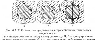
In Fig. 2; a, b, c, d show straight-sided, involute and triangular spline profiles. The most common spline profile is straight-sided, but now splines with an involute profile have also begun to be used, which provides better centering of parts than straight-sided ones.
Triangular splines are used only for light loads and on small diameter shafts.
Spline joints with movable fits are assembled manually without adjustment. Spline connections are distinguished by the method of centering the sleeve relative to the shaft.
There are three ways to center the shaft: along the sides of the splines (Fig. 2, e), along the outer diameter (Fig. 2, f), and along the inner diameter (Fig. 2, g).
Rice. 2. Spline connections: a, b – straight-sided; c – involute; g – triangular; d – centered on the sides; e – centered along the outer diameter; g – centered along the inner diameter
When centering accuracy is not essential and at the same time it is necessary to ensure sufficient strength of the connection, centering is used on the sides of the splines (universal joint in cars).
When it is necessary to achieve kinematic accuracy in mechanisms (machine tools, cars, etc.), centering along one of the diameters is used. Centering along the outer diameter, as it is more economical, is used for thermally untreated female parts, as well as for those parts whose hardness after heat treatment allows calibration by broaching. If the hardness of the female part does not allow calibration, then centering along the inner diameter is used.
Fixed joints that have an interference fit are assembled in special devices or by heating the part before pressing.
After assembly, movable spline joints are checked for rolling, stationary joints are checked for runout.
Before assembling spline joints, it is necessary to make sure that the external chamfers and rounding of the internal corners of the splines are present and in good condition, since if these elements are performed incorrectly, the splines may jam when assembling the joint. In stressed joints, the female part is usually pressed onto the shaft with a special device; It is not recommended to assemble such connections with a hammer.
For very tight spline joints, it is advisable to heat the female part to 80-120° C before pressing. After pressing, the female part should be checked for axial and radial runout (Fig. 3).
Rice. 3. Checking the assembled spline connection for runout
In easy-to-release and movable spline joints, the female parts are installed in place under the influence of little force and even by hand. In this case, the covering parts, in addition to checking for runout, are checked for rolling. In a correctly assembled assembly unit, pitching or relative displacement of the female and male parts under the influence of manually generated torque is completely unacceptable.
Critical spline connections are also checked for paint.
Types of keys
The main types of keys are divided into two types: stressed and unstressed. Among which are the following types of keys:
- Wedges. A special type that differs in the angle of inclination of the upper edge. In general, the division into types is based on the classification of key joints. It is installed in the groove using physical force, using the impact method. The use of this type of connection allows you to achieve the required voltage. The cut wedge, being in the groove, expands it from the inside. Due to the pressing force, the shaft and hub rotate together. It is used quite rarely, since its use requires individual adjustment. This can be considered a disadvantage for mass production of mechanisms. The main purpose is to use it in low-speed transmissions and fixed connection units.
Among the wedge keys there are:- mortise;
- on a flat;
- friction;
- without head and with head.
- Segmental. They are produced in the form of a segment plate driven into a groove. Produced by milling. They are widely used in production, as they are easy to manufacture, do not require special precision when cutting and are easy to install. It differs in installation in a deeper groove, in comparison with analogues. A deep groove is not suitable for heavy loads, as it significantly reduces the strength of the shaft, so it is used for small torques.
Long hubs can have multiple keys installed because they have a fixed length. Perform a safety function against shearing and crushing. - Prismatic. They are distinguished by parallel edges that are installed in a groove and fix the hub. In such cases, the working faces are the lateral ones. They are a non-stressed type of keyed joints, so there is a possibility of corrosion at the joint. To avoid corrosion, the coupling and shaft are connected with interference. The ends are usually produced with rounded or flat ends. For a rounded type, the working surface is considered to be the length of the straight edges. The groove is cut using a cutter. The force is transmitted by pressing the surface of the groove onto the key, which transmits torque to the hub groove. This type of parallel key connection is often used for moving connections, so additional fastening with screws is used. Like many other types, it functions as a fuse during crushing and shearing.
- Cylindrical. The pins in such keys are made in the form of cylinders. I work in tension with a hole at the end of the shaft, which is drilled to fit the corresponding key sizes. Used in cases where the hub is installed at the end of a shaft. Requires a special approach to the installation of keyed connections. Allows work on shear and crushing. Therefore, the choice of key is made based on the crushing strength.
Based on the type of landing, the following are distinguished:
- Free – used in cases where it is quite difficult to carry out welding work and there is a need for movable coupling of parts during work.
- Dense - needed to create clutches, the movement of which during operation is carried out in one spatial position.
Additional requirements reflecting the needs of the country's economy
A.1 The standard does not apply to connections designed before the entry into force of this standard, as well as to keyed connections assembled by fitting or selecting keys.
A.2 Material of keys - clean-drawn steel for segment keys in accordance with GOST 8786-68 or section 4.
A.3 It is allowed, in technically justified cases (hollow and stepped shafts, transmission of reduced torques, etc.), to use smaller cross-sectional sizes of keys on shafts of large diameters than those indicated in Table 2, with the exception of the output ends of the shafts.
A.4 For non-essential connections, it is allowed to connect the bottom of the groove with the side walls with a chamfer at an angle of 45°, equal to the radius R
.
A.5 A loose connection between the key and the shaft and bushing is allowed. Limit deviations for loose connection of groove width b
must comply with the tolerance fields for the shaft - H9, for the bushing - D 10.
A.6 Allowed for slot width b
shaft and bushing any combination of tolerance fields specified in table 2.
A.7 For heat-treated parts, maximum deviations in the size of the shaft groove width are allowed, corresponding to the tolerance field H11, the size of the sleeve groove width is D 10.
A.8 Control of the dimensions of the keyways and their location relative to the corresponding cylindrical surfaces - according to GOST 24109 - GOST 24111; GOST 24115 - GOST 24117; GOST 24119; GOST 24120.
A.9 Series 2 (Table 3) can also be used for non-critical connections (when transmitting low torques at low rotation speeds that do not affect the durability of parts; during short-term operation of the connection, etc.).
A.10 Depending on the accepted processing and measurement base, it is allowed to indicate instead of t
1 in the working drawing, the nominal size for the shaft is
d
-
t
1 with the maximum deviation for
t
1 according to table 2 and for the bushing instead of
t
2 the size
d
-
t
2 with the maximum deviation for
t
2 according to table 2.
A.11 The weight of the keys is indicated in Appendix B.
A.12 For products designed before 01/01/80, the maximum deviations in the dimensions of keyed connections given in Appendix B are allowed.
A.13 Surface roughness parameters of keyed joint elements are given in Appendix D.
Designations on the drawings
In the drawings, the designation of parallel keys is based on the GOST regulatory document. They are divided into keyways: high, normal height and guides. Their working faces are the lateral ones.
In the assembly drawing, the designation is made taking into account the shaft diameter, torque, cross-section and length.
For example:
Key 3–20Х12Х120 GOST 23360-78; Where 3 is the design, 20X12 is the section, 120 is the length.
Download GOST 23360-78
The designation of other types of keys in the images is carried out in the same way, based on the corresponding GOSTs developed for each individual model. The specified designation must clearly characterize the part, which is very important for obtaining a reliable connection. After all, even the slightest gap can cause rapid wear of working units and loss of efficiency during operation.
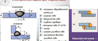
Keyed connections with prismatic high keys according to GOST 10748-79
In table Figure 3 shows the dimensions of tall parallel keys with increased load-bearing capacity.
Table 3
These keys have two versions :
- with rounded ends;
- with flat ends.
Their use is advisable when the female part is made of a material with low strength, for example, silumin.
Range of key lengths according to GOST 10748-79 in mm
22, 28, 32, 36, 40, 45, 50, 56, 63, 70, 80, 90, 100, 110, 120, 140, 160, 180, 200, 250, 280, 320, 360, 400, 450, 500.
Symbols for tall parallel keys
An example of a designation for a key of version 1 according to GOST 10748-79 with dimensions b=20mm, h=18mm, l=100mm:
Key 20x18x100 GOST 10748-79
The same, execution 2:
Key 2 - 20x18x100 GOST 10748-79
Advantages and disadvantages
Like any type of connection, keyed connections have a number of advantages and disadvantages. The advantages of keyed connections include the simplicity of most types of keys. At the same time, installation and replacement of such a part is easy and quick. Thanks to this, they are widely used in mechanical engineering. Also provides protection function.
Disadvantages include weakening of the hub and shaft. It arises from increased stress and reduced cross-section. Also, the weakening of parts is caused by the cut groove, which reduces the axial strength of the shaft.
To minimize the shortcomings, you need to ensure that the key is not skewed in the groove. To do this, you need to ensure that there is no gap, which is done by individually manufacturing and adjusting the key. Because of this, any type of keyed joints are rarely used in large-scale production. If it is not possible to ensure the absence of misalignment, the working contact area decreases, as a result of which the degree of maximum load decreases.
Also, the presence of a gap causes a runout effect, especially at high speeds. This will lead to rapid wear of working parts. Because of this, such a connection is rarely used for rapidly rotating shafts. To select a suitable key, it is better to use the table of key connections.
Key material
For the manufacture of keyed joints, calibrated rolled metal is used. The most commonly used steel is grade 45. It is a regular type of carbon steel, which is often used to produce high-strength parts. The steel is used in the form of a 1 m long bar.
In some cases, carbon steel grade 50 can be used. It is necessary when increased strength properties of the resulting keys are required. Less commonly used are alloy steels, for example, grade 40x, which is characterized by a high hardness index achieved by heat treatment.
Download GOST 8787-68
Steel blanks are processed using cutters, drilling machines, chopping machines, grinders and other tools. The machines used have a control unit that allows, using numerical programs, to produce a part with the required parameters.
The price of the resulting key is quite low, so purchasing the necessary part is quite easy. But in some cases, when there is an urgent need to obtain a key, you can make it yourself. Most often, such a need arises in agriculture, where during seasonal work breakdowns often occur that need to be repaired. At the same time, the nearest points of sale of the necessary parts are located at a distance of several tens of kilometers.
With a small amount of tools on hand and a blank made of the appropriate material, you can quickly make a temporary replacement. If the technical specifications are observed, the resulting part can fully replace the factory one, but it is best to purchase a key of the required strength and geometric parameters at the first opportunity. This is necessary to avoid premature wear of the mechanisms.
Sometimes other materials, such as high quality plastic, may be used for production. Wood can be used as a material, most often in the manufacture of furniture.
It is better to use different types of wood as a material; for a dowel, a softer material than the main one is suitable. This will protect the main structure from damage in case of increased load. It is easier to replace a key than a large structural unit.
To prevent moisture from penetrating into reinforced concrete structures, special dowels called waterstop are used. They are made from high quality rubber and PVC. This allows you to achieve the required degree of waterproofness and resistance to solutions of aggressive chemicals.
Tolerances of keyed connections
This definition is significant. To ensure quality of work, tolerances for keyed connections are assigned
This is important to know. Defines keyed connections GOST 2.308–79 “Unified system of design documentation
Indication on the drawings of tolerances for the shape and location of surfaces.” This is the corresponding documentary base.
Numerical parameters of location tolerances are set taking into account the following relationships: T (steam) = 0.6 T (w); T(sim0) = 4.0 T(w).
Where the indicated designations provide:
— T (w) – tolerance for the width of the keyway b.
— T (par) – specified parallelism parameter.
— T (sim) – symmetry tolerance value in diametrical terms.
The obtained calculated parameters of these determinations are closer to the standard ones. For this purpose, they are guided by GOST 24643.