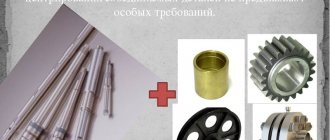
The key is the main part that is part of the key connection. The steel products in question have cut grooves, which is their distinctive feature. In general, they are necessary to connect nodes. And their primary function is the ability to transmit torque between nodes.
Before determining the types of keys, it is worth noting that the following types of metal grades are used in the manufacture of this product:
- steel 45
- steel 50
- steel 60
So, there are 5 types of dowels:
- wedge
- prismatic
- segmental
- cylindrical
- tangential
Next, we will continue to consider the design, purpose and application of the above varieties of steel material.
Advantages and disadvantages
Like any type of connection, keyed connections have a number of advantages and disadvantages. The advantages of keyed connections include the simplicity of most types of keys. At the same time, installation and replacement of such a part is easy and quick. Thanks to this, they are widely used in mechanical engineering. Also provides protection function.
Disadvantages include weakening of the hub and shaft. It arises from increased stress and reduced cross-section. Also, the weakening of parts is caused by the cut groove, which reduces the axial strength of the shaft.
Material and voltage
For the manufacture of a standardized connector, medium-carbon, clean-drawn steel is used. The main steel grades are St6, St45, St50. The steel used must have a bearing stress of at least 600 MPa. This value largely depends on the material from which the engine or machine hub is made. Basically, steel is used to produce the hub. Cast iron is less commonly used. If the hub is made of steel, then with a fixed connection the stress can be in the range from 150 to 210 MPa. For a cast iron hub this figure ranges from 90 to 120 MPa. If the load is constant, then the voltage can be increased.
The tension in the key at the cut line should be in the range from 70 to 120 MPa. Increased stresses may be allowed if the load is constant
The gearbox output shaft for the keyed connection is made of steel. It can be one-sided or two-sided. Double-sided is installed in the case when torque is transmitted from the gearbox to two cars. If necessary, the second machine can be disconnected and only one side can be operated. Or you can install a single-sided shaft.
Spline connections
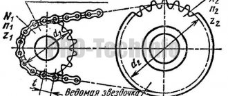
A gear shaft is a cylindrical part, on the outer surface of which depressions (splines) are evenly spaced. There are teeth between the cavities. The teeth fit into the cavities of the mounted part, forming a gear (spline) connection.
The profiles of teeth and cavities are straight-sided, involute (the sides of the tooth profile are outlined by an involute) and triangular.
According to GOST 2.409–74, the toothed surfaces of shafts and the holes of parts connected to the shafts are drawn in a simplified manner.
In Fig. 9.22, a
shows a simplified image of a shaft with a toothed section.
The generatrices of the cylinder of the depressions must intersect the chamfer boundary line and pass along its image. When depicting a shaft in a longitudinal section, the generatrices of the cylinder of the depressions are shown as a solid main line, and the teeth are conditionally aligned with the plane of the drawing and shown uncut (Fig. 9.22, a
).
The image of the end of the toothed part of the shaft shows the profile of only one tooth and two cavities; the circle limiting the protrusions is depicted as a solid main line. The arc of a circle limiting the depressions is depicted as a solid thin line (Fig. 9.22, b
), the chamfer is not shown in this view. If necessary, it is allowed to depict a larger number of teeth and cavities.
Rice. 9.22.
Spline surfaces:
a, b –
on the rod,
in
– in section;
d, e
– in the hole;
e, g
– involute
In sections perpendicular to the axis of the toothed part of the shaft (Fig. 9.22, in
), draw out one tooth and two cavities and also draw an arc of the circle of the cavities.
If parts with jagged holes are drawn in a longitudinal section, the depressions are conditionally aligned with the plane of the drawing (Fig. 9.22, d). The image of the end of the toothed hole shows the profile of one tooth and two cavities; the arc of the circle of the cavities is drawn as a solid thin line (Fig. 9.22, d
).
All the rules discussed above are also applied when depicting the details of gear joints of involute and triangular profiles. The drawings of these parts are supplemented with images of the forming dividing cylinders (Fig. 9.22, f
) and dividing circles (Fig. 9.22,
g
), which are drawn with thin dash-dotted lines.
Three methods are used to center the hole of a part on a shaft with a gear connection of a straight block profile: along the inner diameter, along the outer diameter and along the sides of the teeth.
Tooth spline connections can be thought of as multi-keyed. An example of a spline connection of two parts is shown in Fig. 9.23.
Rice. 9.23.
Spline connection
Spline connections are designated on assembly drawings as follows:
• connections with number of teeth z = 8, internal diameter d
= 36 mm, outer diameter /) = 40 mm, tooth width
b
= = 7 mm, with centering along the inner diameter, with fit according to the centering diameter and size:
• the same, when centering along the outer diameter with a fit according to the centering diameter and size:
• the same, when centered on the sides:
APPENDIX A (mandatory). Additional requirements reflecting the needs of the country's economy
APPENDIX A (required)
A.1 This standard does not apply to connections designed before the date of this standard, or to keyed connections assembled by fitting or matching keys.
Read also: How to draw a watermelon on your nails?
A.2 Material of keys - clean-drawn steel for segment keys in accordance with GOST 8786-68 or section 4.
A.3 It is allowed in technically justified cases (hollow and stepped shafts, transmission of reduced torques, etc.) to use smaller cross-sectional sizes of keys on shafts of large diameters than those indicated in Table 2, with the exception of the output ends of the shafts.
A.4 For non-essential connections, it is allowed to connect the bottom of the groove with the side walls with a chamfer at an angle of 45°, equal to the radius .
A.5 A loose connection between the key and the shaft and bushing is allowed. The maximum deviations for a free connection of the groove width must correspond to the tolerance fields for the shaft - H9, for the sleeve - D10.
A.6 Any combination of tolerance fields specified in Table 2 is allowed for the groove width of the shaft and bushing.
A.7 For heat-treated parts, maximum deviations in the size of the shaft groove width are allowed, corresponding to the tolerance field H11, the size of the sleeve groove width is D10.
A.8 Control of the dimensions of the keyways and their location relative to the corresponding cylindrical surfaces - according to GOST 24109 - GOST 24111; GOST 24115 - GOST 24117; GOST 24119; GOST 24120.
A.9 Series 2 (Table 3) can also be used for non-critical connections (when transmitting low torques at low rotation speeds that do not affect the durability of parts; during short-term operation of the connection, etc.).
A.10 It is allowed, depending on the accepted processing and measurement base, to indicate instead of the working drawing the nominal size for the shaft with the maximum deviation for according to Table 2 and for the bushing instead of the size with the maximum deviation for according to Table 2.
A.11 The weight of the keys is indicated in Appendix B.
A.12 For products designed before 01/01/80, the maximum deviations in the dimensions of keyed connections given in Appendix B are allowed.
A.13 Surface roughness parameters of keyed joint elements are given in Appendix D.
Groove drawing according to GOST (ESKD)
A groove is a narrow and long slot.
The groove drawing is carried out on the basis of GOST 2.109-73 - a unified system of design documentation (ESKD).
You can download this simple drawing for free to use for any purpose. For example, for placement on a nameplate or sticker.
How to draw a drawing:
You can draw a drawing either on a sheet of paper or using specialized programs. No special engineering knowledge is required to complete simple sketch drawings.
A sketch drawing is a drawing made “by hand”, observing the approximate proportions of the depicted object and containing sufficient data for the manufacture of the product.
The design drawing with all the technological data for manufacturing can only be completed by a qualified engineer.
To designate in the drawing, you must perform the following operations:
1. Draw an image; 2. Add dimensions (see example); 3. Specify the technical requirements for manufacturing (read more about the technical requirements below in the article).
It is most convenient to draw on a computer. Subsequently, the drawing can be printed on paper using a printer or plotter. There are many specialized programs for drawing on a computer. Both paid and free.
This image shows how simple and quickly drawing can be done using computer programs.
List of programs for drawing on a computer:
1. KOMPAS-3D; 2. AutoCAD; 3. NanoCAD; 4. FreeCAD; 5. QCAD.
Having studied the principles of drawing in one of the programs, it is not difficult to switch to working in another program. Drawing methods in any program are not fundamentally different from each other. We can say that they are identical and differ from each other only in convenience and the presence of additional functions.
Technical requirements:
For the drawing, it is necessary to indicate dimensions sufficient for manufacturing, maximum deviations and roughness.
The technical requirements for the drawing should indicate:
1) Manufacturing and control method, if they are the only ones that guarantee the required quality of the product; 2) Indicate a specific technological method that guarantees that certain technical requirements for the product are met.
A drawing is a projection image of a product or its element, one of the types of design documents containing data for the production and operation of the product.
A drawing is not a drawing. The drawing is made according to the dimensions and scale of the real product (structure) or part of the product. Therefore, to carry out drawing work, the work of an engineer with sufficient experience in producing drawing work is necessary (however, to beautifully display a product for booklets, it is quite possible that you will need the services of an artist who has an artistic view of the product or part of it).
A drawing is an artistic image on a plane created by means of graphics (brush, pencil or specialized program).
A drawing can be either an independent document or part of a product (structure) and technical requirements related to surfaces processed together. Instructions for joint processing are placed on all drawings involved in the joint processing of products.
For more information on drawings, technical requirements for design and indication of manufacturing methods, see GOST 2.109-73. See the list of standards for the development of design documentation here.
Information for ordering drawings:
In our design organization you can order a drawing of any product (both parts and assemblies), which will include a drawing of the groove as an element of the design documentation of the product as a whole. Our design engineers will develop documentation in the shortest possible time in strict accordance with your technical specifications.
Key material dimensions
During production, the dimensions of the key material are taken into account. In most cases, the rod is delivered to the production site. Its length can be about 1000 millimeters, in some cases it is produced to order. The most common key sizes are:
- 4×4.
- 5×5.
- 22×22.
- 25×25.
- 32×18.
- 40×40.
Do not forget that weight also depends on size. In addition, various alloys are used in the production of products of certain sizes. The size of the connecting element is selected depending on the load that will be applied. In addition, the size is influenced by the dimensions of the connected products.
At the time of product release, quality control is carried out using several different methods, including visual inspection.
The shape largely depends on the area of application of the product in question. The following types are distinguished:
- Wedges.
- Prismatic.
- Segmental.
- Tangential.
- Cylindrical.
Steel is characterized by fairly high ductility to machining. In most cases, the product is obtained from a workpiece, which is a rod.
Application
The main application of keyed connections is mounting on a shaft using a grooved connection. In most cases, the keyway resembles a wedge. This type of connection of parts allows the shaft and hub not to rotate relative to each other’s axis. The fixed position of the hub to the shaft with a key allows for high efficiency when transmitting force.
Most often, keyed connections can be found in mechanical engineering, during the construction of machine tools. It is often used in the production of cars and other mechanisms, where increased reliability of fixing machine parts is required. High reliability is achieved thanks to the function of the shaft safety unit with keyway.
The key acts as a fuse in cases where the maximum torque level is exceeded. In such cases, the key is sheared, absorbing the excessive load and removing it from the shaft and hub.
Due to its properties, it has become widespread in mechanical engineering; it is characterized by high efficiency, ease of manufacture and installation, and low cost. Such characteristics are especially important in industrial production, especially in agriculture. At the height of the season, there are often cases of breakdowns of individual components that need to be replaced as quickly as possible. Most often found in baler units.
Considering all of the above, the main positions for which a key is needed are highlighted:
- Ensuring the safety of connected nodes under increased loads.
- Achieving a high degree of fixation of individual elements of a mechanical assembly.
- Performs the function of preventing rotation of the unit and hub.
- The reliability of such a connection exceeds the reliability of analogues when fixing the shaft with parts.
In general, you can find a keyed connection in almost any complex mechanism, which is due to its technical characteristics.
Designations on the drawings
In the drawings, the designation of parallel keys is based on the GOST regulatory document. They are divided into keyways: high, normal height and guides. Their working faces are the lateral ones.
In the assembly drawing, the designation is made taking into account the shaft diameter, torque, cross-section and length.
Key 3–20Х12Х120 GOST 23360-78; Where 3 is the design, 20Х12 is the section, 120 is the length.
Download GOST 23360-78
The designation of other types of keys in the images is carried out in the same way, based on the corresponding GOST standards developed for each individual model. The specified designation must clearly characterize the part, which is very important for obtaining a reliable connection. After all, even the slightest gap can cause rapid wear of working units and loss of efficiency during operation
Types of keys
The main types of keys are divided into two types: stressed and unstressed. Among which are the following types of keys:
- Wedges. A special type that differs in the angle of inclination of the upper edge. In general, the division into types is based on the classification of key joints. It is installed in the groove using physical force, using the impact method. The use of this type of connection allows you to achieve the required voltage. The cut wedge, being in the groove, expands it from the inside. Due to the pressing force, the shaft and hub rotate together. It is used quite rarely, since its use requires individual adjustment. This can be considered a disadvantage for mass production of mechanisms. The main purpose is to use it in low-speed transmissions and fixed connection units.
Among the wedge keys there are:- mortise;
- on a flat;
- friction;
- without head and with head.
- Segmental. They are produced in the form of a segment plate driven into a groove. Produced by milling. They are widely used in production, as they are easy to manufacture, do not require special precision when cutting and are easy to install. It differs in installation in a deeper groove, in comparison with analogues. A deep groove is not suitable for heavy loads, as it significantly reduces the strength of the shaft, so it is used for small torques.
Long hubs can have multiple keys installed because they have a fixed length. Perform a safety function against shearing and crushing. - Prismatic. They are distinguished by parallel edges that are installed in a groove and fix the hub. In such cases, the working faces are the lateral ones. They are a non-stressed type of keyed joints, so there is a possibility of corrosion at the joint. To avoid corrosion, the coupling and shaft are connected with interference. The ends are usually produced with rounded or flat ends. For a rounded type, the working surface is considered to be the length of the straight edges. The groove is cut using a cutter. The force is transmitted by pressing the surface of the groove onto the key, which transmits torque to the hub groove. This type of parallel key connection is often used for moving connections, so additional fastening with screws is used. Like many other types, it functions as a fuse during crushing and shearing.
- Cylindrical. The pins in such keys are made in the form of cylinders. I work in tension with a hole at the end of the shaft, which is drilled to fit the corresponding key sizes. Used in cases where the hub is installed at the end of a shaft. Requires a special approach to the installation of keyed connections. Allows work on shear and crushing. Therefore, the choice of key is made based on the crushing strength.
Based on the type of landing, the following are distinguished:
- Free – used in cases where it is quite difficult to carry out welding work and there is a need for movable coupling of parts during work.
- Dense - needed to create clutches, the movement of which during operation is carried out in one spatial position.
Classification
It directly depends on the shape of the connectors used. The form is divided into types:
- Segmental.
- Prismatic.
- Round.
- Tangential.
- Wedges.
According to their classification, compounds can be:
- Tense.
- Not tense.
A stress-free connection is obtained if prismatic, round or segment connectors are used. They eliminate installation stress. They are installed on the shafts with tension. This ensures tight fastening, centering and eliminates corrosion.
When installing a wedge or tangential liner, a tension or assembly connection occurs. The tangential inlay is similar to the wedge inlay and is its subtype. When installing them, radial stress appears, which leads to unbalanced operation of the mechanism.
A feather key can have a flat or rounded end. The rounded part is easier to install. The presence of a connector with a flat end prevents its movement along the shaft.
The segment connector is installed on gearboxes that operate at low rotation speeds. This is due to the fact that a deep groove is made under the liner, which reduces the strength of the shaft. They are easily installed in the groove and simply removed. The deep fit in the groove ensures the stability of the connector and eliminates the need for additional fasteners.
Varieties
Taking into account their shape, elements are divided into several categories. This allows them to be used in various mechanisms. The key is:
- Klinovaya. Installed in the groove by driving it in. This type is used in connections with light loads. Used to transmit torque to a pulley or hub.
- Segmental. It is made in the shape of a hemisphere. For installation, it is necessary to equip a deep groove of the appropriate configuration. Large slot sizes reduce the shaft's resistance to mechanical load.
- Prismatic. It is made in the shape of a rectangular parallelepiped. In some cases, rounding the ends is acceptable. Needed to form connections that transmit torque. The maximum load is on the side surfaces. Like other parts, the parallel key protects the mechanisms from overload. An element of this type requires precise sizing.
- Cylindrical. Designed for installation when the pulley is located at the end of the shaft. Manufacturers produce elements of this type in the shape of a cylinder. The grooves in the workpieces are made by drilling.
Before replacing the key, take its configuration into account. This way it is possible to obtain a reliable connection between the workpieces.
Project recommendations
During the design process, a number of recommendations must be followed:
- for one shaft element, it is advisable to use the same cross-section, and better yet, the same length, the guide is the shaft with a smaller cross-section;
- with a small torque it is advisable to mount w. smaller section, in relation to the dimensions of the shaft section, than indicated in the state standard;
- if there are several keyways, then they are placed on one generatrix;
- if it is necessary to mount two segment wheels, then they are installed along the shaft in one groove in the hub. If you install several sh. in one connection, this will weaken the adhesion. If there is such a need, then it is better to use a splined (gear) clutch.
- It is better to avoid keyed coupling with thin-walled hollow shafts.
Key material
For the manufacture of keyed joints, calibrated rolled metal is used. The most commonly used steel is grade 45. It is a regular type of carbon steel, which is often used to produce high-strength parts. The steel is used in the form of a 1 m long bar.
In some cases, carbon steel grade 50 can be used. It is necessary when increased strength properties of the resulting keys are required. Less commonly used are alloy steels, for example, grade 40x, which is characterized by a high hardness index achieved by heat treatment.
Download GOST 8787-68
Steel blanks are processed using cutters, drilling machines, chopping machines, grinders and other tools. The machines used have a control unit that allows, using numerical programs, to produce a part with the required parameters.
The price of the resulting key is quite low, so purchasing the necessary part is quite easy. But in some cases, when there is an urgent need to obtain a key, you can make it yourself. Most often, such a need arises in agriculture, where during seasonal work breakdowns often occur that need to be repaired. At the same time, the nearest points of sale of the necessary parts are located at a distance of several tens of kilometers.
With a small amount of tools on hand and a blank made of the appropriate material, you can quickly make a temporary replacement. If the technical specifications are observed, the resulting part can fully replace the factory one, but it is best to purchase a key of the required strength and geometric parameters at the first opportunity. This is necessary to avoid premature wear of the mechanisms.
Sometimes other materials, such as high quality plastic, may be used for production. Wood can be used as a material, most often in the manufacture of furniture.
It is better to use different types of wood as a material; for a dowel, a softer material than the main one is suitable. This will protect the main structure from damage in case of increased load. It is easier to replace a key than a large structural unit.
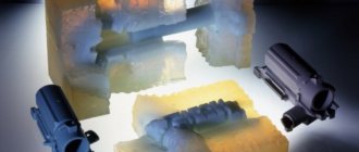
To prevent moisture from penetrating into reinforced concrete structures, special dowels called waterstop are used. They are made from high quality rubber and PVC. This allows you to achieve the required degree of waterproofness and resistance to solutions of aggressive chemicals.
Advantages and disadvantages of dowels
- Keyed connections have many advantages, which is why they are widely used in mechanical engineering, although there are many other ways to transmit torque between rotating parts.
- Simple design. The keys can be easily calculated and selected for any shaft-hub system.
- Convenient installation. They are easy to install and remove using ordinary hand tools.
- Price. Affordable cost is one of the main advantages. Both wholesale and retail dowels can be purchased at very low prices.
Of course, there are also disadvantages. The main ones are:
- weakening of the shaft and hub by keyways, which, among other things, are stress concentrators;
- insufficiently reliable operation of keys under shock, reverse and cyclic loads.
Designations on the drawings
In the drawings, the designation of parallel keys is based on the GOST regulatory document. They are divided into keyways: high, normal height and guides. Their working faces are the lateral ones.
In the assembly drawing, the designation is made taking into account the shaft diameter, torque, cross-section and length.
Key 3–20Х12Х120 GOST 23360-78; Where 3 is the design, 20Х12 is the section, 120 is the length.
The designation of other types of keys in the images is carried out in the same way, based on the corresponding GOST standards developed for each individual model. The specified designation must clearly characterize the part, which is very important for obtaining a reliable connection. After all, even the slightest gap can cause rapid wear of working units and loss of efficiency during operation