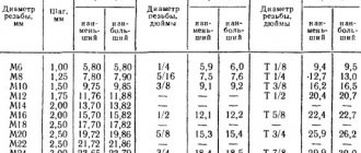
Bolt table with thread pitches for bolts, nuts, screws and threaded rods.
How to determine the thread size without a thread gauge, read our special article.
| Thread diameter | Thread pitch, mm | |||
| Main thread pitch, mm / Thread hole diameter, mm | Fine thread pitch, mm / Thread hole diameter, mm | |||
| Small | Petty 2 | Superfine | ||
| M 1 | 0.25 / 0.75 | (0.2) / 0.8 | — | — |
| M 1.2 | 0.25 / 0.95 | (0.2) / 1 | — | — |
| M 1.4 | 0.3 / 0.9 | (0.2) / 1.2 | — | — |
| M 1.6 | 0.35 / 1.2 | (0.2) / 1.4 | — | — |
| M 1.8 | 0.35 / 1.5 | (0.2) / 1.6 | — | — |
| M 2 | 0.4 / 1.6 | (0.25) / 1.75 | — | — |
| M 2.2 | 0.45 / 1.75 | (0.25) / 1.95 | — | — |
| M 2.5 | 0.45 / 2.05 | (0.35) / 2.15 | — | — |
| M 3 | 0.5 / 2.5 | (0.35) / 2.65 | — | — |
| M 3.5 | 0.6 / 2.9 | (0.35) / 3.15 | — | — |
| M 4 | 0.7 / 3.3 | 0.5 / 3.5 | — | — |
| M 4.5 | 0.7 / 3.8 | — | — | — |
| M5 | 0.8 / 4.2 | 0.5 / 4.5 | — | — |
| M 5.5 | — | (0.5) / 4.5 | — | — |
| M 6 | 1 / 5 | 0.75 / 5.2 | 0.5 / 5.5 | — |
| M 7 | 1 / 6 | (0.75) / 6.2 | 0.5 / 6.5 | — |
| M 8 | 1.25 / 6.7 | 1 / 7 | 0.75 / 7.2 | 0.5 / 7.5 |
| M 9 | 1.25 / 7.7 | 1 / 7.95 | 0.75 / 8.2 | 0.5 / 8.5 |
| M 10 | 1.5 / 8.5 | 1.25 / 8.7 | 1 / 9 | 0.75 / 9.2 |
| M 12 | 1.75 / 10.2 | 1.5 / 10.5 | 1.25 / 10.7 | 1 / 11 |
| M 14 | 2 / 12 | 1.5 / 12.5 | 1.25 / 12.6 | 1 / 13 |
| M 15 | — | 1.5 / 13.4 | 1 / 13.95 | — |
| M 16 | 2 / 14 | 1.5 / 14.5 | — | 1 / 15 |
| M 18 | 2.5 / 15.4 | 2 / 16 | 1.25 / 16.6 | 1 / 17 |
| M 20 | 2.5 / 17.4 | 2 / 18 | 1.25 / 18.6 | 1 / 19 |
| M 22 | 2.5 / 19.4 | 2 / 20 | 1.5 / 20.5 | 1 / 21 |
| M 24 | 3 / 20.9 | 2 / 22 | 1.5 / 22.5 | 1 / 23 |
| M 27 | 3 / 23.9 | 2 / 25 | 1.5 / 25.5 | (1) / 26 |
| M 30 | 3.5 / 26.4 | 2 / 28 | 1.5 / 28.5 | (1) / 29 |
| M 33 | 3.5 / 29.4 | 2 / 31 | 1.5 / 31.5 | — |
| M 36 | 4 / 31.9 | 3 / 33 | 2 / 34 | 1.5 / 34.5 |
| M 39 | 4 / 34.9 | 3(4) / 35.9 | 2 / 37 | 1.5 / 37.5 |
| M 42 | 4.5 / 37.4 | 3(4) / 37.9 | 2 / 40 | 1.5 / 40.5 |
| M 45 | 4.5 / 40.4 | 3(4) / 40.9 | 2 / 43 | 1.5 / 43.5 |
| M 48 | 5 / 42.8 | 3 / 44.9 | 2 / 46 | 1.5 / 46.5 |
| M 52 | 5 / 46.8 | (4)3 / 48.9 | 2 / 50 | 1.5 / 50.5 |
| M 56 | 5.5 / 50.4 | 4 / 51.9 | 3(2) / 53 | 1.5 / 54.5 |
| M 60 | 5.5 / 64.4 | 4 / 55.8 | 3(2) / 67 | 1.5 / 58 |
| M 64 | 6 / 57.8 | 4 / 59.8 | 3 / 61 | 2(1.5) / 62 |
| M 68 | 6 / 61.8 | 4 / 63.8 | 3 / 65 | 2(1.5) / 66 |
Full table with threads from M0.25 to M600 is available in PDF
The letter “M” near the thread diameter lets us know that the thread is metric, i.e. not inch, but metric
Metric thread pitch
Metric thread pitch is the distance in millimeters between two identical points located on the same side adjacent turns of the profile. Measured parallel to the thread axis. This is one of the key parameters of a threaded product, along with diameters (nominal, internal, external), direction of rotation, profile type, number of strokes. GOST 8724-2002 indicates the compliance of these characteristics in the range of diameters from 0.25 to 600 mm and pitches from 0.075 to 8 mm.
In accordance with the regulatory document, manufacturing enterprises can produce fasteners with 2 types of metric thread pitches - small and large. For one size of fastener, the standard defines only one large and several small thread pitches. For fasteners with a nominal diameter of less than 1 mm, in accordance with GOST, only large ones are installed, from 1 mm to 64 mm - large and small, from 72 mm to 600 mm - only small.
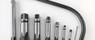
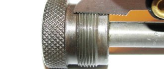
Measuring with a thread gauge
Accurately identifying the threads on a fastener is critical before selecting and installing the correct fittings.
How to measure thread:
- Use a combination caliper to measure the thread diameter. It is worth taking into account that the threads of the used fitting may wear out and become distorted, so calculations may not be accurate.
- Use a thread gauge to determine the number of threads per inch. For metric connections, the distance between the threads is calculated. To do this, you need to place the device on the thread until it fits snugly, and then compare your measurements with the thread diagram.
- If the port is located at an angle, determine the angle of inclination using a protractor on the sealing surface. The center line of the fitting and gauge should be parallel.
Using a combination of three tools, identifying connectors is easy. The use of a caliper, thread gauge and protractor allows accurate measurements of most connections.
A caliper is used to measure the diameter of an external internal thread. When comparing calibration measurements to thread diagrams, keep in mind that threads on connections that have been in service may be worn and distorted from use. This results in inaccurate comparisons with thread tables.
For English, British and other European threads, the pitch meter has an inch scale. However, for metric parts, the device will determine the distance between threads in millimeters.
The protractor is used by placing it on the sealing surface. The center line of the fitting end and gauge should be parallel. In English, the thread size system and pitch (number of threads per inch) are specified along with the thread type.
When using a thread gauge, you need to align it with the threads and make sure that it fits snugly. Match the measurement to the thread, then calculate the diameter using a caliper.
Internal connections are measured by inserting the identification part of the device into the connector on the sealing surface. Make sure that the center lines of the connection and the protractor are parallel. This will allow you to determine the correct angle.
Using the above methods, you can measure the thread pitch of any fastener. This can be either a nut with a flange and a locking plastic insert, or a washer with an internal cone.
Lecture 6
Lecture 6. Threaded connections
- General concept of thread: type, pitch, thread progress.
- Image and designation of thread.
- Grooves.
- Connecting parts using threads.
- Bolted connection, its actual, simplified and symbolic designation.
6.1 General concept of thread: type, pitch, thread progress.
The connection between individual assembly units and machine parts is carried out using various connections. Existing connections are divided into detachable and permanent.
Permanent joints include rivet and welded joints, as well as joints formed by flaring, gluing, interference fit, and others, the disassembly of which is impossible without damaging the parts of the product.
Detachable connections include threaded, wedge, keyed, splined (toothed). Such connections can be disassembled without disturbing the fixing elements.
Of all types of connections used in mechanical engineering, threaded connections are the most common, since they are the most reliable and convenient in shape for assembly and disassembly, have small dimensions, are easy to manufacture, and allow precise installation of the parts to be connected and any degree of tightening with fasteners. The disadvantage of threaded connections is the presence of stress concentrators in the threaded parts, which reduce their strength.
Threaded connections are those in which the mating parts are connected using threads or threaded fasteners. These connections are the most common type of detachable connections. Threaded connections are also used to transform motion, for example, in lead and load screws. The main element of the connection is a thread with a corresponding profile established by the standard.
A thread (GOST 11708-82) is a surface formed by the screw movement of a flat contour along a cylindrical or conical surface.
The thread thread is that part of its protrusion that covers the threaded part within a range of up to 360°.
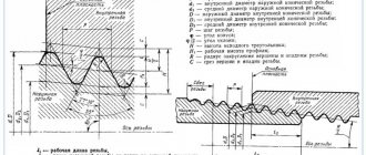
The thread formed on the outer surface is called external (Fig. 6.1a), on the internal surface - internal (Fig. 6.1b).
In accordance with the “Image of Threads” standard, which establishes the rules for depicting and marking threads on drawings of all industries and construction, threads are depicted:
a) on the rod - with solid main lines along the outer diameter and solid thin lines along the inner diameter (Fig. 6.1a).
In images obtained by projection onto a plane parallel to the axis of the rod, a continuous thin line along the internal diameter of the thread is drawn along the entire length of the thread (Fig. 6.1a). In the views obtained by projection onto a plane perpendicular to the axis of the rod, an arc approximately equal to 3/4 of the circle, open anywhere, is drawn along the internal diameter of the thread (Fig. 6.1a, b).
b) in the hole - with solid main lines along the internal diameter of the thread and solid thin lines - along the outer diameter (Fig. 6.1b).
It is easy to remember that a thin line along the grooves of the thread is always drawn along the “metal” no closer than 0.8-1 mm to the solid main line and no more than the pitch value R.
a) b)
Figure 6.1
Hatching in sections and sections is carried out to the line of the outer diameter of the thread on the rod and to the line of the internal diameter in the hole, i.e. in both cases to the solid main line.
A thread is called right-handed if the helix rises from bottom to top to the right of the observer, and left-handed if the helix rises from bottom to top to the left of the observer.
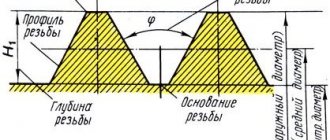
Thread pitch P is the distance between adjacent profile points of the same name, measured along the axis, see Figure 6.2. P is a standard value and is selected according to tables, for example, for metric threads - GOST 8724-81. The thread profile is the contour of the thread section in a plane passing through the axis.
Figure 6.2
Metric thread. The thread profile is triangular. The angle of the metric thread profile is 60º, see Figure 6.3.
Figure 6.3
The designation of metric threads indicates the letters M and the size of the outer diameter of the thread, for example, M16. Each thread has one large step and several small ones. The small step is always indicated in the notation, and the large step is omitted. Figure 6.4a shows a metric thread with an outer diameter of 24 mm and a large pitch P = 2.5 (selected according to GOST 8724-81). Figure 6.4b shows a metric thread with an outer diameter of 24 mm and a fine pitch P = 1.5 mm, left. The symbol LH is used to indicate left-hand threads.
Thread pitch, the distance between the parallel sides of the profile of two adjacent turns, measured along the axis. Usually Sh.r. measured along the line where the width of the turns is equal to the width of the depressions. For multi-way threads, in addition to the pitch, a stroke is distinguished equal to the distance by which the screw will move along the axis during one full revolution of it in a stationary nut, i.e., the pitch of the same helical thread line. The thread stroke is equal to the product Sh.r. by the number of thread starts. For a single-stroke thread, the lead is equal to the pitch.
a b
Figure 6.4
The trapezoidal thread profile looks like an isosceles trapezoid with an angle of 30º, see Figure 6.5. In the designation of a single-start trapezoidal thread, the letters “Tr”, outer diameter and pitch are applied, for example, Tr 48x8. The notation Tr 60x14 LH denotes a left-handed trapezoidal thread with an outer diameter of 60 mm, pitch P = 14 mm.
Figure 6.5
Thrust thread. The thread profile has the form of an unequal trapezoid, see fig. 6.6.
Figure 6.6
The designation of a single-start thrust thread indicates the letter S, outer diameter and pitch, for example, S48x6. For left-hand threads, LH is added, for example, S52x12 LH. The dimensions of thrust single-start threads are given in table. 7(GOST 10177-89).
In mechanical engineering, right-hand threads are most often used. They are single- and multi-pass. For a single-start thread (Fig. 6.7a), only one end of the thread is visible at the end of the screw or nut; for a double-start thread (Fig. 6.7b), two turns are visible; for a three-start thread (Fig. 6.7c), three turns are visible. Single-start threads have small helix angles, are characterized by a high coefficient of friction and are used where a reliable connection is required (for fastening threads). For multi-start threads, the helix angle is significantly greater than for single-start threads. Such threads are used in cases where rapid movement along the thread with minimal friction is necessary. For multi-start threads, the thread stroke is equal to the pitch P multiplied by the number of starts. For a single-start thread, the stroke is equal to the pitch P.
a B C
Figure 6.7
6.2 Image and designation of thread.
The thread designation is shown in Fig. 6.1. In reality, there is no sharp transition from the thread to the smooth surface of the rod or hole. This is explained by the gradual exit of the cutting part of the tool from the body of the part at the end of the thread cutting operation or the presence of a fence part. The profile of the helical groove in this case is distorted. The area where the tool exits is called the thread run-out (Fig. 6.8).
Figure 6.8
Usually it is included in the total thread length. The size of the thread length on the rod and in the hole is indicated, as a rule, without a run (Fig. 6.9a, c). If necessary, the length of the thread with a run-out is shown as in Fig. 6.9b,c. An undercut made to the stop is depicted as shown in Fig. 6.10a, c. It is allowed to depict an undercut of the thread, as shown in Figure 6.10b, d.
In drawings where threads are not made, the end of a blind threaded hole may be depicted as shown in Figure 6.11, even if there is a difference between the depth of the thread hole and the length of the thread.
Figure 6.9
a B C D
Figure 6.10
A solid thin line depicting the thread on the rod should intersect the chamfer boundary line (Fig. 6.9c).
Figure 6.11
6.3 Grooves
A thread-cutting tool (cutter or die) always has a certain distance (along the thread axis) between the actual cutting edges and the edge of the tool. Therefore, the thread will turn out to be “under-cut” due to the tool resting on the uncut end. This may cause assembly problems. The groove provides a standard thread profile along its entire length, and the screwed part can be brought close to the stop against the unthreaded end.
For external and internal threads, the groove has the form of an annular groove, the dimensions of which are selected for metric threads according to GOST 27148-86, and for other threads according to GOST 10549-80.
For educational purposes, grooves can be selected according to relative dependencies (depending on the thread pitch P). This makes them easier to remember, and the standards are developed based on approximately the same dependencies. For selection of groove sizes, see Figure 6.12.
Figure 6.12
6.4 Connecting parts using threads
The main standard fasteners for threaded connections are bolt, nut, stud, screw and washer.
A threaded connection is a connection of 2 parts, one of which has an external thread and the other an internal one.
Sections of threaded connections in a hole show only that part of the thread that is not covered by the thread of the rod.
For a detachable connection of two or more parts, a bolted connection, a stud connection, and a screw connection are used. Welding is used to permanently connect two or more parts.
An important element of the image of threaded connections is the image of threaded parts in section. The outer diameter of the rod thread corresponds to the outer diameter of the thread in the hole, and the inner diameter of the rod thread corresponds to the diameter of the hole (Fig. 6.13a).
Figure 6.13
In the image of a threaded connection, preference is given to the thread of the rod, and the thread of the hole is shown only where it is not covered by the image of the rod (Fig. 6.13b).
For educational purposes, the parameters of a bolted connection are calculated depending on the diameter of the thread and the thickness of the parts being connected, see Figure 6.14. The turnkey size S can be selected according to the GOST 24671-84 standard, depending on the thread diameterd, or determined using the approximate formula S≈1.6d and rounded to the standard value. The bolt, nut and washer are shown uncut.
Three dimensions are indicated on the drawing of a bolted connection: thread diameter; hole diameter; bolt length.
In accordance with GOST 2.315-68, in assembly drawings and general view drawings, connecting parts can be depicted in a simplified manner (without chamfers, gaps and roundings) as shown in Figure 6.15. GOST 2.315-68 provides for simplified and conventional images of the most common fasteners on assembly drawings.
Figure 6.14
Figure 6.15
The symbol for a bolt connection is shown in Figure 6.16.
Figure 6.16
studfiles.net
Measuring thread pitch without a thread gauge
For metric fasteners, thread pitch is used instead of TPI. Distance is also measured in millimeters.
To determine the thread pitch, a caliper is used to calculate the distance from the top of one thread to the next. The formula used for this is M2 x 4 x 5 mm, where M2 refers to the diameter of the bolt (in millimeters), i.e. 4 is the thread pitch in millimeters, which means it is equal to 4 mm between each thread peak, and 5M is bolt length.
Thread pitch is used to measure the threads of a bolt or nut to ensure they fit together. If the threads of the bolt and nut are different, they either do not grip or wear out the threads, resulting in an unusable connection.
Small threaded fasteners have a denser helical structure and are usually less pronounced. A coarse threaded connection has larger and deeper threads. This means that if the threads are slightly damaged, it may still work. Most standard metric fasteners have fine and coarse threads. Each of them can be identified using or thread pitch.
In the US and UK, fasteners typically have thread sizes ranging from ¼ to 20 inches and ¼ to 28 inches. To determine which of these threads is coarse and which is fine, you simply need to take the TPI number (20 and 28) and compare them.
Don't forget that coarse thread means the thread is larger, so smaller ones will be able to fit within an inch. So 20 means it's a coarse thread and 28 means it's a fine thread. TPI and thread pitch will vary depending on the diameter of the fastener, so the value will not always be 20 and 28.
For metric fasteners, similar parameters would be represented as M8 x 1.25 or M8 x 1. For thread pitch, the distance between two points is the second number, meaning the higher the number, the fewer threads. It follows that M8 x 1.25 is a coarse thread, and M8 x 1 is a fine thread.
Marking
The marking of a threaded connection consists of a combination of letters and numbers.
Example of deciphering thread markings
- A number to indicate a step reduced compared to the standard one. If a standard step is used, it is not set.
- Letter to indicate thread type:
- M is for metric.
- BSW for inch.
- MK for metric tapered.
- MJ Cylindrical for the aerospace industry: reliable connections operating at high temperatures.
- G - cylindrical pipe.
- R pipe conical.
- Kr round for sanitary products.
- Tr Trapezoidal – for transmitting torque and translational motion in worm gears.
- S Resistant, with different angles of inclination of the sides, for highly loaded connections.
- E Edison round - for light bulb sockets.
- Nominal diameter in mm or inches with fractions expressed as simple fractions.
- Pitch in millimeters or fractions of an inch.
- Stroke for multi-start connections.
- LH in case of left-hand thread.
- Tolerance field designation, consists of letters and numbers
Measuring threads with a caliper
The first step is to determine whether the threads are tapering. To do this, place the points of the caliper on either side of the object that needs to be measured. Align it to the outside of the threads at the lower end, away from the head. This is how the width is determined.
Next, you need to move the tip so that it touches the threads. The measurement should appear on the screen if the instrument has a display. Otherwise, you will need to rely on the numbers on the sliding part. You should then do the same on the threaded area near the head of the fastener. If the number is higher at the head, then it is a tapered thread.
You can also use a caliper to measure the diameter. If the thread is tapered, measure at the 4th or 5th thread down from the head, i.e. in the middle of the threaded area. If it does not taper, then you can measure anywhere along the thread. When using a caliper, you may notice that there are several places where the arms do not meet closely together, sometimes along the edge of the ruler. There is no need to place what needs to be measured in these spaces.
The numbers should be placed in a standard measurement. Once the pitch value is obtained, you can measure the length of the bolt or screw from under the head and place all the numbers into a standard measurement. It will have the diameter, then the thread pitch and the length. If a metric screw has a diameter of 4 millimeters, a thread pitch of 0.4 mm and a length of 8 mm, then the calculation will be M4 x 0.4 x 8M. For an American screw this could be 1/4" in diameter, 20 TPI and 1" long. The formula will be: 1/4 inch x 20 x 1 inch.
Selecting thread parameters
When choosing fasteners, you need to pay attention to the thread pitch. The strength of the connection, its resistance to vibration and other destructive factors depends on this. In cases where installation is carried out by a large number of elements or special characteristics are not required from it, the main pitch of a metric thread can be used. Such elements are often used in construction, repairs, furniture assembly and other work when a lot of quick installation with sufficient reliability is required. At high values of dynamic loads, including vibration, it is better to turn to products with a fine thread pitch. For example, car wheel rims are attached to the hub only with fine threads so that the nuts do not loosen due to vibrations that occur during movement. Such hardware is in demand in precision engineering, automobile and aircraft manufacturing, in the production of machine tools, etc.
Threads of different pitches are marked in different ways. If the technical documentation simply indicates an M12 bolt, this means that the hardware has a nominal diameter of 12 mm with a main thread pitch of 1.75 mm. When marked M12x1.25, it means that the bolt stud has a diameter of 12 mm with a fine pitch of 1.25 mm. That is, if no number is indicated after the diameter, the thread pitch is standard or basic; if a number is indicated, it is a fine or superfine thread pitch.
Measuring rivets
Rivets are a kind of fasteners consisting of two parts: a head and a mandrel. The cap is the short side that needs to be measured for its length and diameter. The mandrel is the long, thin end that comes off the rivet during the installation process.
First of all, you need to place the head into the round holes on a special rivet gauge. The holes have different diameters into which rivets fit. When they are inserted into the hole, the cap should fit snugly.
If there is a gap, the size is too large for the rivet. In the opposite situation it is too small. Using the selection method, you need to determine which size most accurately reflects the parameters of the fastener.
Next you need to measure the length of the rivet. To do this, you need to attach the cap to the open upper areas. Make sure that the washer or flange of the rivet is pressed well.
large, small, table of correspondence between main and fine steps
Metric thread pitch
We are often faced with the problem of selecting the required fastener, and the question arises of what thread pitch to choose. Let's figure out what threading is and what you should pay attention to.
A thread is a type of surface with alternating projections and depressions. There are several types of carving. The most popular are metric and imperial. In this article we will only touch on metric threads, since they are more common.
Metric thread is the main type of fastening thread. It differs in pitch and nominal diameter. The thread pitch is equal to the distance between two identical points of the nearest profiles of the same name lying in the same plane. Despite such a complex definition, it is very easy to understand - this is the distance between two thread protrusions.
In turn, metric threads in accordance with GOST 8724-81 can be with a large (main) or fine pitch. It is considered that a step from 1 to 68 mm is a large step, higher than 68 mm is only a small step. Also, it should be noted that a small thread pitch can be different for the same rod diameter, while a large one has only one value.
Typically, fine thread pitches are used in environments with little vibration or shock. Thus, fasteners with fine pitches are often used in aircraft manufacturing and for fastening high-precision mechanisms in mechanical engineering. As for the usual step, such fasteners are the most popular and are used almost everywhere.
Like any other thread, metric threads have their pros and cons. The advantages include high reliability of fastening, convenience during installation and dismantling and, of course, the low cost of hardware with this thread. There are relatively few disadvantages, or rather there are only two of them - this is the concentration of stress in the thread cavities, which reduces the installation strength of the connection and the use of locking means in some cases.
Pitch for main and fine threads
| Thread | Thread pitch P, mm | |||
| Main thread M | Fine thread M | |||
| small | small 2 | superfine | ||
| M1 | 0.25 | (0.2) | — | — |
| M1.2 | 0.25 | (0.2) | — | — |
| M1.4 | 0.3 | (0.2) | — | — |
| M1.6 | 0.35 | (0.2) | — | — |
| M1.8 | 0.35 | (0.2) | — | — |
| M2 | 0.4 | (0.25) | — | — |
| M2.2 | 0.45 | (0.25) | — | — |
| M2.5 | 0.45 | (0.35) | — | — |
| M3 | 0.5 | (0.35) | — | — |
| M3.5 | 0.6 | (0.35) | — | — |
| M4 | 0.7 | 0.5 | — | — |
| M5 | 0.8 | 0.5 | — | — |
| M6 | 1.0 | 0.75 | 0.5 | — |
| M8 | 1.25 | 1.0 | 0.75 | 0.5 |
| M10 | 1.5 | 1.25 | 1.0 | 0.75 |
| M12 | 1.75 | 1.5 | 1.25 | 1.0 |
| M14 | 2.0 | 1.5 | 1.25 | 1.0 |
| M16 | 2.0 | 1.5 | — | 1.0 |
| M18 | 2.5 | 2.0 | 1.5 | 1.0 |
| M20 | 2.5 | 2.0 | 1.5 | 1.0 |
| M22 | 2.5 | 2.0 | 1.5 | 1.0 |
| M24 | 3.0 | 2.0 | 1.5 | 1.0 |
| M27 | 3.0 | 2.0 | 1.5 | (1.0) |
| M30 | 3.5 | 2.0 | 1.5 | (1.0) |
| M33 | 3.5 | 2.0 | 1.5 | — |
| M36 | 4.0 | 3.0 | 2.0 | 1.5 |
| M39 | 4.0 | 3.0 | 2.0 | 1.5 |
| M42 | 4.5 | (4.0) 3.0 | 2.0 | 1.5 |
| M45 | 4.5 | (4.0) 3.0 | 2.0 | 1.5 |
| M48 | 5.0 | (4.0) 3.0 | 2.0 | 1.5 |
| M52 | 5.0 | (4.0) 3.0 | 2.0 | 1.5 |
| M56 | 5.5 | 4.0 | 3.0 (2.0) | 1.5 |
| M60 | 5.5 | 4.0 | 3.0 (2.0) | 1.5 |
| M64 | 6.0 | 4.0 | 3.0 | 2.0 (1.5) |
| M68 | 6.0 | 4.0 | 3.0 | 2.0 (1.5) |
offers a wide range of hardware, both with small and large threads.
krepzevs.com
Metric thread. Profile.
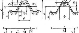
Metric thread profile according to GOST 9150 (ST SEV 180)
The nominal thread profile and the dimensions of its elements must correspond to those indicated in the figure and table.
d is the outer diameter of the external thread (bolt); D—outer diameter of the internal thread (nut); d2 is the average diameter of the bolt; D2 - average diameter of the nut; d1 - internal diameter of the bolt; D1 - internal diameter of the nut; P - thread pitch; H is the height of the original triangle; R is the nominal radius of curvature of the bolt root; H1 - working height of the profile.
Notes:
- The shape of the bolt thread root is not regulated and can be either rounded or flat-cut. A rounded cavity shape is preferred.
- The shape of the nut thread root is not regulated.
The table shows the dimensions of the thread profile elements. The shape of the screw thread cavities is not regulated by the standard; rounding of the depressions (with radius R) reduces stress concentration and increases the strength of the screw under cyclic loading.
According to GOST 24705 (ST SEV 182), the thread is metric, the main values of thread diameters are determined by the formulas:
where d3 is the internal diameter of the bolt.