Screws, bolts and studs are the most common externally threaded components. Most often, they fall into the hands of a home craftsman ready-made. But it happens that you need to make some tricky bolt or non-standard pin. The blank for such a part is a rod, the diameter of which must correspond to the thread being cut.
The diameter of the rod for an external thread depends on the nominal diameter of the thread and the size of the thread pitch. All this information is usually indicated on the drawing of the part in the form of the designation M10 × 1.5. The letter “M” denotes a metric thread, the number after the letter is the nominal diameter, the number after the sign “x” is the thread pitch. When using the main (large) step, it may not be indicated. Main thread pitch
defined by the standard and is the most preferred.
When choosing the diameter of a rod for external threads, they are guided by the same principles as when choosing holes for internal threads. It has been established that the best thread quality is obtained if the diameter of the rod is slightly smaller than the nominal diameter of the thread being cut. When cutting, the metal is slightly squeezed out and the thread profile is complete.
If the diameter of the rod is much smaller than the required one, then the tops of the threads will be cut off; if it is larger, then the die simply will not screw onto the rod or will break during operation.
For each combination of diameter and thread pitch there is an optimal rod diameter
. The easiest way to determine this diameter is from the table, which shows the most common threads that a home craftsman may encounter. The main thread pitch for each nominal diameter is highlighted in bold in the table.
| Thread | Thread pitch | Nominal rod diameter (maximum) |
| M2 | 0,4 | 1,93-1,95 (1,88) |
| 0,25 | 1,95-1,97 (1,91) | |
| M2.5 | 0,45 | 2,43-2,45 (2,37) |
| 0,35 | 2,45-2,47 (2,39) | |
| M3 | 0,5 | 2,89-2,94 (2,83) |
| 0,35 | 2,93-2,95 (2,89) | |
| M4 | 0,7 | 3,89-3,94 (3,81) |
| 0,5 | 3,89-3,94 (3,83) | |
| M5 | 0,8 | 4,88-4,94 (4,78) |
| 0,5 | 4,89-4,94 (4,83) | |
| M6 | 1 | 5,86-5,92 (5,76) |
| 0,75 | 5,88-5,94 (5,79) | |
| 0,5 | 5,89-5,94 (5,83) | |
| M8 | 1,25 | 7,84-7,90 (7,73) |
| 1 | 7,86-7,92 (7,76) | |
| 0,75 | 7,88-7,94 (7,79) | |
| 0,5 | 7,89-7,94 (7,83) | |
| M10 | 1,5 | 9,81-9,88 (9,69) |
| 1 | 9,86-9,92 (9,76) | |
| 0,5 | 9,89-9,94 (9,83) | |
| 0,75 | 9,88-9,94 (9,79) | |
| M12 | 1,75 | 11,80-11,86 (11,67) |
| 1,5 | 11,81-11,88 (11,69) | |
| 1,25 | 11,84-11,90 (11,73) | |
| 1 | 11,86-11,92 (11,76) | |
| 0,75 | 11,88-11,94 (11,79) | |
| 0,5 | 11,89-11,94 (11,83) | |
| M14 | 2 | 13,77-13,84 (13,64) |
| 1,5 | 13,81-13,88 (13,69) | |
| 1 | 13,86-13,92 (13,76) | |
| 0,75 | 13,88-13,94 (13,79) | |
| 0,5 | 13,89-13,94 (13,83) | |
| M16 | 2 | 15,77-15,84 (15,64) |
| 1,5 | 15,81-15,88 (15,69) | |
| 1 | 15,86-15,92 (15,76) | |
| 0,75 | 15,88-15,94 (15,79) | |
| 0,5 | 15,89-15,94 (15,83) | |
| M18 | 2 | 17,77-17,84 (17,64) |
| 1,5 | 17,81-17,88 (17,69) | |
| 1 | 17,86-17,92 (17,76) | |
| 0,75 | 17,92-17,94 (17,86) | |
| M20 | 2,5 | 19,76-19,84 (19,58) |
| 1,5 | 19,81-19,88 (19,69) | |
| 1 | 19,86-19,92 (19,76) | |
| 0,75 | 19,88-19,94 (19,79) | |
| 0,5 | 19,89-19,94 (19,83) |
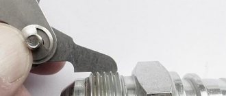
The main tool for cutting external threads is a die. Most often, round continuous dies in the form of a hardened steel nut are used.
To form the cutting edges, the die threads are crossed by through longitudinal holes, which also provide chip exit. To facilitate entry, the outer threads of the thread have an incomplete profile. A die holder is used to rotate the die.
- a tool with a socket for a die and long handles. There are also split and sliding (clump) dies, but these are rare in the home workshop.
To reduce friction and obtain clean threads, a lubricant is used on steel rods - mineral oil or kerosene, and on copper rods - turpentine. At the end of the rod, to facilitate entry, a chamfer must be made with a width of at least the size of the thread pitch.
Metric threads. Diameters of rods and tolerances on them for metric threads M3-M50, made with dies. Drill diameters M1-M10 for drilling holes for metric threads. Cutting threads with dies and taps.
- External thread:
The die is clamped in the collar with screws located along its contour. - At the end of the rod on which the thread needs to be cut, a chamfer is removed at an angle on a sharpening machine
- At the end of a rod firmly clamped in a vice with a chamfer in the form of a truncated cone, install a crank with a die exactly in a horizontal plane and rotate the crank clockwise with both hands (looking from above), if the thread is right-handed, with slight pressure on the die. Sometimes it is recommended to smoothly rotate the knob clockwise, sometimes after each half-turn, turn it back a little to break the chips. The main thing is to lubricate all the working blades well so that the threads do not break and the die does not become dull.
- The diameter of the rods for external metric threads should be selected according to Table 1.
Table 1. Diameters of rods for metric threads made with dies
| Diameters | Tolerances on rod diameter | Diameters | Tolerances on rod diameter | ||
| threads | rod | threads | rod | ||
| Coarse pitch thread | |||||
| 3 | 2,94 | -0,06 | 12 | 11,88 | -0,12 |
| 3,5 | 3,42 | -0,08 | 16 | 15,88 | -0,12 |
| 4 | 3,92 | -0,08 | 18 | 17,88 | -0,12 |
| 4,5 | 4,42 | -0,08 | 20 | 19,86 | -0,14 |
| 5 | 4,92 | -0,08 | 22 | 21,86 | -0,14 |
| 6 | 5,92 | -0,08 | 24 | 23,86 | -0,14 |
| 7 | 6,90 | -0,10 | 27 | 26,86 | -0,14 |
| 8 | 7,90 | -0,10 | 30 | 29,86 | -0,14 |
| 9 | 8,90 | -0,10 | 33 | 32,83 | -0,17 |
| 10 | 9,90 | -0,10 | 36 | 35,83 | -0,17 |
| 11 | 10,88 | -0,12 | 39 | 38,83 | -0,17 |
| Fine pitch thread | |||||
| 4 | 3,96 | -0,08 | 24 | 23,93 | -0,14 |
| 4,5 | 4,46 | -0,08 | 25 | 24,93 | -0,14 |
| 5 | 4,96 | -0,08 | 26 | 25,93 | -0,14 |
| 6 | 5,96 | -0,08 | 27 | 26,93 | -0,14 |
| 7 | 6,95 | -0,10 | 28 | 27,93 | -0,14 |
| 8 | 7,95 | -0,10 | 30 | 29,93 | -0,14 |
| 9 | 8,95 | -0,10 | 32 | 31,92 | -0,17 |
| 10 | 9,95 | -0,10 | 33 | 32,92 | -0,17 |
| 11 | 10,94 | -0,12 | 35 | 34,92 | -0,17 |
| 12 | 11,94 | -0,12 | 36 | 35,92 | -0,17 |
| 14 | 13,94 | -0,12 | 38 | 37,92 | -0,17 |
| 15 | 14,94 | -0,12 | 39 | 38,92 | -0,17 |
| 16 | 15,94 | -0,12 | 40 | 39,92 | -0,17 |
| 17 | 16,94 | -0,12 | 42 | 41,92 | -0,17 |
| 18 | 17,94 | -0,12 | 45 | 44,92 | -0,17 |
| 20 | 19,93 | -0,14 | 48 | 47,92 | -0,17 |
| 22 | 21,93 | -0,14 | 50 | 49,92 | -0,17 |
- Internal thread:
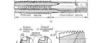
cut using taps. A tap is a metal-cutting tool for cutting internal threads in pre-drilled holes. There are manual (rotated using a crank) and machine, nut and tool (master and die). When cutting deep threads, a set of three taps is usually used: the first tap (designation - one notch) is preliminary, the second (two notches) cuts the thread and the third (three marks or without bottom) calibrates it. Nut taps are suitable for cutting short threads (as in a nut) and have sequential cutting edges; after passing the entire length, a full thread is obtained. - The correct choice of hole diameters is of great importance. If the diameter is larger than it should be, the internal threads will not have a full profile and the result will be a weak connection. With a smaller hole diameter, it is difficult for the tap to enter it, which leads to the breaking of the first turns of the thread or to jamming and breakage of the tap. The diameter of the hole for a metric thread can be approximately determined by multiplying the thread size by 0.8 (for example, for an M2 thread, the drill should have a diameter of 1.6 mm, for M3 - 2.4-2.5 mm, etc. (see. table).
- It is necessary to lubricate the cutting part of the tap with thick oil (for example, grease), animal fat (lard) or vegetable oil - it is better not to use liquid motor oil, as it often spoils the thread - and insert it into the hole.
- Then you need to carefully ensure that the tap runs exactly along the axis of the hole to avoid breakage. After cutting 4-5 turns, the tap is removed from the hole and cleared of chips. After this, it is lubricated again and screwed into the hole again, another 4-5 turns are cut, continuing the operation until it stops (for a blind hole or until the tap comes out (for a through hole).
- Then they clean the first tap, put it in place and take a tap with two marks, lubricate it, manually screw it into the hole and, as soon as it starts to cut into the metal, put a driver on it. After cutting every 5-6 turns, the tap is cleaned of chips and lubricated until the hole passes completely.
- Then they clean the second tap, put it in place, take the last tap with three marks, also lubricate it with grease, screw it into the hole by hand until it engages, put on the driver and carefully calibrate the thread. Cleaning of chips and lubrication is repeated as before.
- Inch taps
cut threads in the same way as metric ones. To cut threads on pipes, clamps are used, usually with adjustable cutting elements in a range of threads for pipes with an internal diameter of 1/4 to 4 inches. Threads on large diameter pipes and stubbles are best cut on screw-cutting lathes. - The diameter of the drill bits for drilling holes for metric threads should be selected according to Table 2.
Table 2. Drill diameters for drilling holes for metric threads
Diameters of rods for metric threads made with dies
| Outer thread diameter, mm | Drill diameter (mm) for | |
| Cast iron, bronze | Steel, brass | |
| 1 | 0,75 | 0,75 |
| 1,2 | 0,95 | 0,95 |
| 1,6 | 1,3 | 1,3 |
| 2 | 1,6 | 1,6 |
| 2,5 | 2,2 | 2,2 |
| 3 | 2,5 | 2,5 |
| 3,5 | 2,9 | 2,9 |
| 4 | 3,3 | 3,3 |
| 5 | 4,1 | 4,2 |
| 6 | 4,9 | 5 |
| 7 | 5,9 | 6 |
| 8 | 6,6 | 6,7 |
| 9 | 7,7 | 7,7 |
| 10 | 8,3 | 8,4 |
Article rating:
This table will help you understand cutting metric threads and possibly reduce waste. The table values can be useful for machine operators, shop foremen, and engineers.
The diameters of rods for cutting metric threads are regulated by GOST 16093-2004.
| Nominal thread diameter d | Thread pitch P | Rod diameter for threading with tolerance range | ||||||
| 4h | 6g | 6e | 6e; 6g | 8g | ||||
| Nominal diameter | Maximum deviation | Nominal diameter | Maximum deviation | Nominal diameter | Maximum deviation | |||
| 1,0 | 0,25 | 0,97 | -0,03 | 0,95 | — | -0,04 | — | — |
| 1,2 | 0,25 | 1,17 | 1,15 | — | — | — | ||
| 1,4 | 0,3 | 1,36 | 1,34 | — | — | — | ||
| 1,6 | 0,35 | 1,55 | 1,53 | — | — | — | ||
| 2 | 0,4* | 1,95 | -0,04 | 1,93 | — | -0,05 | — | — |
| 0,25 | 1,97 | -0,03 | 1,95 | — | -0,04 | — | — | |
| 2,5 | 0,45 | 2,45 | -0,04 | 2,43 | — | -0,06 | — | — |
| 3 | 0,5* | 2,94 | 2,92 | 2,89 | — | — | ||
| 0,35 | 2,95 | -0,03 | 2,93 | — | -0,04 | — | — | |
| 4 | 0,7* | 3,94 | -0,06 | 3,92 | 3,89 | -0,08 | — | — |
| 0,5 | 3,94 | -0,04 | 3,92 | 3,89 | -0,06 | — | — | |
| 5 | 0,8* | 4,94 | -0,07 | 4,92 | 4,88 | -0,10 | 4,92 | -0,18 |
| 0,5 | 4,94 | -0,04 | 4,92 | 4,89 | -0,06 | — | — | |
| 6 | 1* | 5,92 | -0,07 | 5,89 | 5,86 | -0,10 | 5,89 | -0,20 |
| 0,75 | 5,94 | -0,06 | 5,92 | 5,88 | -0,09 | — | — | |
| 0,5 | 5,94 | -0,04 | 5,92 | 5,89 | -0,06 | — | — | |
| 8 | 1,25* | 7,90 | -0,08 | 7,87 | 7,84 | -0,11 | 7,87 | -0,24 |
| 1 | 7,92 | -0,07 | 7,89 | 7,86 | -0,10 | 7,89 | -0,20 | |
| 0,75 | 7,94 | -0,06 | 7,92 | 7,88 | -0,09 | — | — | |
| 0,5 | 7,94 | -0,04 | 7,92 | 7,89 | -0,06 | — | — | |
| 10 | 1,5* | 9,88 | -0,09 | 9,85 | 9,81 | -0,12 | 9,85 | -0,26 |
| 1 | 9,92 | -0,07 | 9,89 | 9,86 | -0,10 | 9,89 | -0,20 | |
| 0,5 | 9,94 | -0,04 | 9,92 | 9,89 | -0,06 | — | — | |
| 0,75 | 9,94 | -0,06 | 9,92 | 9,88 | -0,09 | — | — | |
| 12 | 1,75* | 11,86 | -0,10 | 11,83 | 11,80 | -0,13 | 11,83 | -0,29 |
| 1,5 | 11,88 | -0,09 | 11,85 | 11,81 | -0,12 | 11,85 | -0,26 | |
| 1,25 | 11,90 | -0,08 | 11,87 | 11,84 | -0,11 | 11,87 | -0,24 | |
| 1 | 11,92 | -0,07 | 11,89 | 11,86 | -0,10 | 11,89 | -0,20 | |
| 0,75 | 11,94 | -0,06 | 11,92 | 11,88 | -0,09 | — | — | |
| 0,5 | 11,94 | -0,04 | 11,92 | 11,89 | -0,06 | — | — | |
| 14 | 2* | 13,84 | -0,10 | 13,80 | 13,77 | -0,13 | 13,80 | -0,29 |
| 1,5 | 13,88 | -0,09 | 13,85 | 13,81 | -0,12 | 13,85 | -0,26 | |
| 1 | 13,92 | -0,07 | 13,89 | 13,86 | -0,10 | 13,89 | -0,20 | |
| 0,75 | 13,94 | -0,06 | 13,92 | 13,88 | -0,09 | — | — | |
| 0,5 | 13,94 | -0,04 | 13,92 | 13,89 | -0,06 | — | — | |
| 16 | 2* | 15,84 | -0,10 | 15,80 | 15,77 | -0,13 | 15,80 | -0,29 |
| 1,5 | 15,88 | -0,09 | 15,85 | 15,81 | -0,12 | 15,85 | -0,26 | |
| 1 | 15,92 | -0,07 | 15,89 | 15,86 | -0,10 | 15,89 | -0,20 | |
| 0,75 | 15,94 | -0,06 | 15,92 | 15,88 | -0,09 | — | — | |
| 0,5 | 15,94 | -0,04 | 15,92 | 15,89 | -0,06 | — | — | |
| 18 | 2* | 17,84 | -0,10 | 17,80 | 17,77 | -0,13 | 17,80 | -0,29 |
| 1,5 | 17,88 | -0,09 | 17,85 | 17,81 | -0,12 | 17,85 | -0,26 | |
| 1 | 17,92 | -0,07 | 17,89 | 17,86 | -0,10 | 17,89 | -0,20 | |
| 0,75 | 17,94 | -0,04 | 17,94 | 17,92 | -0,06 | — | — | |
| 20 | 2,5* | 19,84 | -0,13 | 19,80 | 19,76 | -0,18 | 19,80 | -0,37 |
| 1,5 | 19,88 | -0,09 | 19,85 | 19,81 | -0,12 | 19,85 | -0,26 | |
| 1 | 19,92 | -0,07 | 19,89 | 19,86 | -0,10 | 19,89 | -0,20 | |
| 0,75 | 19,94 | -0,06 | 19,92 | 19,88 | -0,09 | — | — | |
| 0,5 | 19,94 | -0,04 | 19,92 | 19,89 | -0,06 | — | — | |
The standard metric thread pitch is indicated
(*)
Pipe thread
Pipe thread
is a group of standards intended for connecting and sealing various types of structural elements using pipe threads. The quality of work when cutting grooves has a great influence on the reliability of the connection and the structure obtained in this way. Particular attention should be paid to the correlation of the thread with the axis of the pipe to which it is applied.
When cutting threads manually using a die, the alignment is far from ideal, which can affect the reliability and quality of the connection. As for the use of tools such as a lathe or tapping machine, the use of tapping heads with a precision tapping knife
, then here the indicators of the applied thread are comparable with the theoretical values.
The ROTHENBERGER concern produces thread-cutting machines, thread-cutting dies, heads, knives that ensure the performance of work with high precision. All equipment fully complies with international standards in this area.
Cylindrical pipe thread, G (BSPP)
Also known as Whitworth carving ( BSW (BritishStandardWhitworth)
).
This type is used for organizing cylindrical threaded connections. It is also used in cases of connecting internal cylindrical threads with external conical threads ( GOST 6211-81).
- GOST 6357-81 - Basic standards of interchangeability. Cylindrical pipe thread.
- ISO R228
- EN 10226
- DIN 259
- BS 2779
- JIS B 0202
Thread parameters
- theoretical profile height (H) - 960491Р;
- designation according to the profile shape - inch thread (profile in the form of an isosceles triangle with an apex angle of 55 degrees);
- maximum pipe diameter is 6 inches (for pipes with a diameter over 6, a welded connection is used).
Example of a symbol:
G - designation of the profile shape (cylindrical pipe thread);
G1 1/2 - nominal diameter (measured in inches);
A – accuracy class (can be A or B).
To designate a left-hand thread, the index LH is used (example: G1 1/2 LH-B-40 - cylindrical pipe thread, 1 1/2 - nominal bore in inches, accuracy class B, make-up length 40 millimeters).
The thread pitch can have one of four values:
Table 1
The main dimensions of cylindrical pipe threads are determined by GOST 6357-81 (BSP). It should be remembered that the thread size in this case conventionally characterizes the lumen of the pipe, despite the fact that in fact the outer diameter is significantly larger.
table 2
| Thread size designation | Step P | Thread diameters | ||
| Row 1 | Row 2 | d=D | d 2 =D 2 | d 1 =D 1 |
| 1/16″ | 0,907 | 7,723 | 7,142 | 6,561 |
| 1/8″ | 9,728 | 9,147 | 8,566 | |
| 1/4″ | 1,337 | 13,157 | 12,301 | 11,445 |
| 3/8″ | 16,662 | 15,806 | 14,950 | |
| 1/2″ | 1,814 | 20,955 | 19,793 | 18,631 |
| 5/8″ | 22,911 | 21,749 | 20,587 | |
| 3/4″ | 26,441 | 25,279 | 24,117 | |
| 7/8″ | 30,201 | 29,039 | 27,877 | |
| 1″ | 2,309 | 33,249 | 31,770 | 30,291 |
| 1.1/8″ | 37,897 | 36,418 | 34,939 | |
| 1.1/4″ | 41,910 | 40,431 | 38,952 | |
| 1.3/8″ | 44,323 | 42,844 | 41,365 | |
| 1.1/2″ | 47,803 | 46,324 | 44,845 | |
| 1.3/4″ | 53,746 | 52,267 | 50,788 | |
| 2″ | 59,614 | 58,135 | 56,656 | |
| 2.1/4″ | 65,710 | 64,231 | 62,762 | |
| 2.1/2″ | 75,184 | 73,705 | 72,226 | |
| 2.3/4″ | 81,534 | 80,055 | 78,576 | |
| 3″ | 87,884 | 86,405 | 84,926 | |
| 3.1/4″ | 93,980 | 92,501 | 91,022 | |
| 3.1/2″ | 100,330 | 98,851 | 97,372 | |
| 3.3/4″ | 106,680 | 105,201 | 103,722 | |
| 4″ | 113,030 | 111,551 | 110,072 | |
| 4.1/2″ | 125,730 | 124,251 | 122,772 | |
| 5″ | 138,430 | 136,951 | 135,472 | |
| 5.1/2″ | 151,130 | 148,651 | 148,172 | |
| 6″ | 163,830 | 162,351 | 160,872 |
d is the outer diameter of the external thread (pipe);
D—outer diameter of the internal thread (coupling);
D1 - internal diameter of the internal thread;
d1 - internal diameter of the external thread;
D2 - average diameter of internal thread;
d2 is the average diameter of the external thread.
Tapered pipe thread, R (BSPT)
Used for organizing pipe conical connections, as well as for connecting internal cylindrical and external conical threads (GOST 6357-81). Based on BSW, it is compatible with BSP.
The sealing function in connections using BSPT is performed by the thread itself (due to its compression at the connection point when the fitting is screwed in). Therefore, the use of BSPT must always be accompanied by the use of a sealant.
This type of thread is characterized by the following parameters:
- GOST 6211-81 - Basic standards of interchangeability. Conical pipe thread.
- ISO R7
- DIN 2999
- BS 21
- JIS B 0203
designation based on the profile shape – inch thread with a taper (profile in the form of an isosceles triangle with an apex angle of 55 degrees, cone angle φ=3°34′48″).
When designating, a letter index of the thread type is used (R for external and Rc for internal) and a digital indicator of the nominal diameter (for example, R1 1/4 - conical pipe thread with a nominal diameter of 1 1/4). The index LH is used to designate left-hand threads.
Thread parameters
Inch thread with taper 1:16 (cone angle φ=3°34′48″). The profile angle at the apex is 55°.
Symbol: letter R for external thread and Rc for internal thread ( GOST 6211-81
— Basic norms of interchangeability. Pipe thread is conical), the numerical value of the nominal diameter of the thread in inches (inch), the letters LH for a left-hand thread. For example, a thread with a nominal diameter of 1.1/4 is designated as R 1.1/4.
Table 3
Designation of thread size, steps and nominal values of the outer, middle and inner diameters of conical pipe threads (R), mm
| Thread size designation | Step P | Thread length | Thread diameter in the main plane | |||
| Working | From the end of the pipe to the main plane | Outer d=D | Average d 2 =D 2 | Internal d 1 =D 1 | ||
| 1/16″ | 0,907 | 6,5 | 4,0 | 7,723 | 7,142 | 6,561 |
| 1/8″ | 6,5 | 4,0 | 9,728 | 9,147 | 8,566 | |
| 1/4″ | 1,337 | 9,7 | 6,0 | 13,157 | 12,301 | 11,445 |
| 3/8″ | 10,1 | 6,4 | 16,662 | 15,806 | 14,950 | |
| 1/2″ | 1,814 | 13,2 | 8,2 | 20,955 | 19,793 | 18,631 |
| 3/4″ | 14,5 | 19,5 | 26,441 | 25,279 | 24,117 | |
| 1″ | 2,309 | 16,8 | 10,4 | 33,249 | 31,770 | 30,291 |
| 1.1/4″ | 19,1 | 12,7 | 41,910 | 40,431 | 38,952 | |
| 1.1/2″ | 19,1 | 12,7 | 47,803 | 46,324 | 44,845 | |
| 2″ | 23,4 | 15,9 | 59,614 | 58,135 | 56,565 | |
| 2.1/2″ | 26,7 | 17,5 | 75,184 | 73,705 | 72,226 | |
| 3″ | 29,8 | 20,6 | 87,884 | 86,405 | 84,926 | |
| 3.1/2″ | 31,4 | 22,2 | 100,330 | 98,851 | 97,372 | |
| 4″ | 35,8 | 25,4 | 113,030 | 111,551 | 110,072 | |
| 5″ | 40,1 | 28,6 | 138,430 | 136,951 | 135,472 | |
| 6″ | 40,1 | 28,6 | 163,830 | 162,351 | 160,872 |
Short way https://bibt.ru
Before cutting a thread, you need to select the diameter of the workpiece for this thread.
When cutting a thread with a die, you must keep in mind that when a thread profile is formed, the metal of the product, especially steel, copper, etc., stretches and the product increases. As a result, the pressure on the surface of the die increases, which leads to heating and adhesion of metal particles, so the thread may become torn.
When choosing the diameter of a rod for external threads, you should be guided by the same considerations as when choosing holes for internal threads. The practice of cutting external threads shows that the best thread quality can be obtained if the diameter of the rod is slightly smaller than the outer diameter of the thread being cut. If the diameter of the rod is less than required, the thread will be incomplete; if it is more, then the die either cannot be screwed onto the rod and the end of the rod will be damaged, or during operation the teeth of the die may break due to overload, and the thread will be torn off.
In table Figure 27 shows the diameters of the rods used when cutting threads with dies.
Table 27 Diameters of threaded rods when cutting with dies
The diameter of the workpiece should be 0.3-0.4 mm less than the outer diameter of the thread.
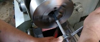
When cutting a thread with a die, the rod is secured in a vice so that the end of the vice protruding above the level of the jaws is 20-25 mm longer than the length of the part being cut. To ensure penetration, a chamfer is filed at the upper end of the rod. Then a die attached to the die is placed on the rod and with slight pressure the die is rotated so that the die cuts in approximately 0.2-0.5 mm. After this, the cut part of the rod is lubricated with oil and the die is rotated in exactly the same way as when working with a tap, i.e. one or two turns to the right and half a turn to the left (Fig. 152, b).
Rice. 152. Technique for cutting threads with a die (b)
To prevent defects and breakage of teeth, it is necessary that the die fits onto the rod without distortion.
Checking the cut internal threads is done with thread plug gauges, and external threads are checked with thread micrometers or thread ring gauges.
The strength of fastening the parts to each other is ensured by screwing the external thread carrier into the internal thread of the second product. It is important that their parameters are maintained in accordance with the standards, then such a connection will not be damaged during operation and will ensure the necessary tightness. Therefore, there are standards for the execution of carvings and its individual elements.
Before cutting, a hole is made inside the part for the thread, the diameter of which should not exceed its internal diameter. This is done using metal drills, the dimensions of which are given in the reference tables.
Cutting external threads with round dies
A simple and reliable way to fasten fixed-detachable connections of various parts are threaded connections with bolts, screws and studs.
To cut threads on them, two thread systems are used: metric, in which the pitch and diameter of the thread are measured in millimeters, and inch, in which the number of threads is determined in 1″ of the length of the cut rod with a diameter indicated in inches.
When cutting threads manually, the most common tool is round dies (cutters), which are divided into solid and split. Using solid dies you can get threads of only one diameter. Split dies make it possible to adjust the diameter of the thread being cut within small limits (0.1-0.3 mm).
When cutting external threads, it is necessary to correctly select the diameter of the rod being cut. If the diameter of the rod is small, the thread will be incomplete, and the strength of the threaded connection will become less. If the diameter of the rod is larger than it should be, then it will be difficult to work with a die due to the fact that when cutting a thread, the diameter of the rod increases due to the deformation of the metal. A larger rod diameter can lead to jamming of the die and stripping of the thread. The diameter of the threaded rod is determined according to the table. 5.
Table 5.
Diameter of threaded rods when cutting with dies
The high friction that occurs when cutting threads leads to strong heating of the tool and dulling of the cutting edges.
To reduce friction, as well as to obtain threads with low roughness, the following lubricants are used: for steel - boiled oil; for cast iron and aluminum - kerosene; for copper - turpentine. Thread cutting on cast iron and bronze workpieces can be done “dry”.
Training task 1 consists of running partial threads on bolts.
The sequence of completing the task is as follows.
1. Preparation for thread running. The outer diameter of the thread is measured with a caliper and the thread system and pitch are determined with a thread gauge.
When selecting solid round dies according to established data, check the roughness of their threaded grooves and pay attention to the sharpness and serviceability of the cutting edges. Do not use dies with nicks or nicks on threaded threads.
The die holder must match the round die. It is installed in the die holder with the marking upwards and secured with special screws 1-3 and 5 (Fig. 187, a). Screw 4 serves to regulate the release in the split die. After the bolt is vertically secured in a vice, the appropriate lubricant is applied to the bolt and die with a brush.
Rice. 187. Cutting external threads with round dies:
a - method of installing a round die on a rod and starting threading; b - cutting threads with round dies; c - solid die; g - split die
2. Reception of thread running. A die with a die holder is placed on the end of the bolt shaft so that the marking on the die is at the top, and the plane of the die is perpendicular to the axis of the bolt, then they try to insert the die into the thread of the bolt, turning it slightly (Fig. 187, a). After the die has entered the bolt thread, the die holder with the die is turned 1/2 turn along the thread and 1/4 turn in the opposite direction. This alternating rotation promotes crushing and better chip removal, facilitates processing and produces threads with lower roughness.
Such movements are performed until the entire length of the thread is passed. When working with solid dies, a full profile thread is obtained in one pass.
After finishing the processing, the die is unscrewed from the bolts and the threads of the die are wiped with a clean rag.
The thread being cut is checked with a nut, which should rotate freely with very little force. Too loose a nut fit (with rocking) is unacceptable,
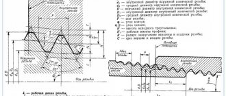
Hole parameters
The following thread parameters are distinguished:
- diameters (internal, external, etc.);
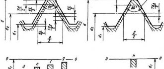
- profile shape, height and angle;
- step and entry;
- others.
The condition for connecting parts to each other is the complete coincidence of the external and internal threads. If any of them are not performed in accordance with the requirements, the fastening will be unreliable.
The fastening can be bolted or stud, which, in addition to the main parts, includes nuts and washers. Before joining, holes are formed in the parts to be fastened, and then cutting is carried out.
To perform it with maximum accuracy, you should first form a hole by drilling, equal to the size of the internal diameter, that is, formed by the tops of the protrusions.
When performing a through design, the diameter of the hole must be 5-10% larger than the size of the bolt or stud, then the following condition is met:
d answer = (1.05..1.10)×d, (1),
where d is the nominal diameter of the bolt or stud, mm.
To determine the hole size of the second part, the calculation is carried out as follows: the pitch value (P) is subtracted from the value of the nominal diameter (d) - the resulting result is the desired value:
d answer = d - P, (2).
The calculation results are clearly demonstrated by the table of threaded hole diameters, compiled according to GOST 19257-73, for sizes 1-1.8 mm with small and main pitches.
Nominal diameter, mm Pitch, mm Hole size, mm 1 0,2 0,8 1 0,25 0,75 1,1 0,2 0,9 1,1 0,25 0,85 1,2 0,2 1 1,2 0,25 0,95 1,4 0,2 1,2 1,4 0,3 1,1 1,6 0,2 1,4 1,6 0,35 1,25 1,8 0,2 1,6 1,8 0,35 1,45 An important parameter is the drilling depth, which is calculated from the sum of the following indicators:
- screw-in depth;
- reserve of external thread of the screwed-in part;
- her undercut;
- chamfers.
In this case, the last 3 parameters are for reference, and the first is calculated through the coefficients for taking into account the material of the product, which are equal for products from:
- steel, brass, bronze, titanium – 1;
- gray and ductile cast iron – 1.25;
- light alloys – 2.
Thus, the screw-in depth is the product of the material factor and the nominal diameter, and is expressed in millimeters.
Download GOST 19257-73
GOST 19256-73 Rods for rolling metric threads. Diameters
Drill diameter for standard metric ISO threads with coarse and fine pitch Reference table Metric and inch dimensions of drilling tools _ Max. Internal Drill Drill Pitch Dia. Diam. Diam. M mm Inch 1.6 0.35 1.321 1.25 3/64 1.8 0.35 1.521 1.45 54 2 0.4 1.679 1.6 1/16 2.2 0.45 1.833 1.75 50 2.5 0.45 2.138 2.05 46 3 0 .5 2.599 2.5 40 3.5 0.6 3.010 2.9 33 4 0.7 3.422 3.3 30 4.5 0.75 3.878 3.8 27 5 0.8 4.334 4.2 19 6 1 5.153 5 9 7 1 6.153 6 15/64 8 1.25 6.912 6.8 H 9 1.25 7.912 7.8 5/16 10 1.5 8.676 8.5 Q 11 1.5 9.676 9.5 3/8 12 1.75 10.441 10.3 Y 14 2 12.210 12 15/32 16 2 14.210 14 35/64 18 2.5 15.744 15.5 39/64 20 2.5 17.744 17.5 11/16 22 2.5 19.744 19.5 49/64 24 3 21.252 21 53/64 27 3 24.252 24 61/64 30 3.5 26.771 26.5 1.3/64 33 3.5 29.771 29.5 1.5/32 36 4 32.270 32 1.1/4 39 4 35.270 35 1.3/8 42 4.2 37.799 37.5 45 4.5 40.799 40.5 48 5 43.297 43 52 5 47.297 47 D = Drill diameter (mm) Dnom = Nominal Tap Diameter (mm) P = Tap Pitch (mm) RECOMMENDED DIAMETERS FOR DRILLING WITH ADX AND CDX SERIES DRILLS The tables show diameters for common standard drills. Drilling with modern drills such as the Dormer ADX and CDX produces a smaller diameter and more accurately shaped hole, so a larger diameter drill should be used to prevent tap breakage. See small table on the right. Metric thread with fine pitch acc. ISO TAP Max. Drill Drill TAP Max. Drill Internal Internal Dia. Diam. Diam. Diam. Diam. MF mm Inch MF mm 3×0.35 2.721 2.65 37 25X1 24.153 24 3.5×0.35 3.221 3.2 1/8 25X1.5 23.676 23.5 4×0.5 3.599 3.5 29 25×2 23.210 2 3 5×0.5 4.599 4.5 16 26×1.5 24.676 24.5 5.5 ×0.50 5.099 5 9 27×1.5 25.676 25.5 6×0.75 5.378 5.3 5 27×2 25.210 25 7×0.75 6.378 6.3 D 28×1.5 26.676 26.5 8×0.75 7.3 78 7.3 9/32 28×2 26.210 26 8×1 7.153 7 J 30×1.5 28.676 28.5 9×1 8.153 8 O 30×2 28.210 28 10×0.75 9.378 9.3 U 32×1.5 30.676 30.5 10×1 9.153 9 T 32×2 30.210 30 1 0×1.25 8.912 .8 8 11/32 33 ×2 31.210 31 11×1 10.153 10 X 35×1.5 33.676 33.5 12×1 11.153 11 7/16 36×1.5 34.676 34.5 12×1.25 10.912 10.8 27/64 36× 2 34.210 34 12×1.5 10.676 10.5 Z 36×3 33.252 33 14×1 13.153 13 17/32 38×1.5 36.676 36.5 14×1.25 12.912 12.8 1/2 39×3 36.252 36 14×1.5 12.676 12.5 31/64 40× 1.5 38.676 38.5 15×1 14.153 14 35/64 40 ×2 38.210 38 15×1.5 13.676 13.5 17/32 40×3 37.252 37 16×1 15.153 15 19/32 42×1.5 40.676 40.5 16×1.5 14.676 14.5 9/16 42×2 40.210 40 18X1 17.153 17 43/64 42 ×3 39.252 39 18X1.5 16.676 16.5 41/64 45×1.5 43.676 43.5 18X2 16.210 16 5/8 45X2 43.210 43 20X1 19.153 19 3/4 45X3 45.252 42 20X1.5 18.676 18.5 47/64 48X1.5 46.676 46.5 20X2 18.210 18 45/64 48X2 46.210 46 22X1 21.153 21 53/64 48X3 45.252 45 22X1.5 20.676 20.5 13/16 50X1.5 48.686 48.2 22X2 20.210 20 25/3 2 50X2 48.210 48 24X1 23.153 23 29/32 50X3 47.252 47 24X1.5 22.676 22.5 7/8 24X2 22.210 22 55/64 Metric thread with coarse pitch acc. ISO for ADX/CDX drills TAP Drill TAP Drill Pitch Dia. Step Dia. M mm M mm 4 0.70 3.40 10 1.50 8.70 5 0.80 4.30 12 1.75 10.40 6 1.00 5.10 14 2.00 12.25 8 1.25 6.90 16 2.00 14.25 76 Threading with DIAMET taps DRILL DRILLS FOR TAPPING HOLES The drill diameter can be calculated from: D = D — P Metric thread with coarse pitch acc. ISO TAP
Selecting drill size
The diameter of the drill for a hole for a metric thread is also determined by formula (2), taking into account its main parameters.
It is worth noting that when cutting in ductile materials, such as steel or brass, the turns increase, so it is necessary to choose a larger drill diameter for the thread than for brittle materials, such as cast iron or bronze.
In practice, drill sizes are usually slightly smaller than the required hole. Thus, Table 2 shows the ratio of the nominal and outer thread diameters, the pitch, the diameters of the hole and the drill for cutting metric threads.
Table 2. The relationship between the main parameters of metric threads with normal pitch and the diameters of the hole and drill
| Nominal diameter, mm | Outer diameter, mm | Pitch, mm | Largest hole diameter, mm | Drill diameter, mm |
| 1 | 0,97 | 0,25 | 0,785 | 0,75 |
| 2 | 1,94 | 0,4 | 1,679 | 1,60 |
| 3 | 2,92 | 0,5 | 2,559 | 2,50 |
| 4 | 3,91 | 0,7 | 3,422 | 3,30 |
| 5 | 4,9 | 0,8 | 4,334 | 4,20 |
| 6 | 5,88 | 1,0 | 5,153 | 5,00 |
| 7 | 6,88 | 1,0 | 6,153 | 6,00 |
| 8 | 7,87 | 1,25 | 6,912 | 6,80 |
| 9 | 8,87 | 1,25 | 7,912 | 7,80 |
| 10 | 9,95 | 1,5 | 8,676 | 8,50 |
As can be seen from the table, there is a certain dimensional limit, which is calculated taking into account thread tolerances.
The size of the drill is much smaller than the hole. So, for example, for an M6 thread, the outer diameter of which is 5.88 mm, and its largest hole value should not exceed 5.153 mm, you should use a 5 mm drill.
A hole for an M8 thread with an outer diameter of 7.87 mm will be only 6.912 mm, which means the drill for it will be 6.8 mm.
The quality of the thread depends on many factors when cutting it: from the choice of tool to the correctly calculated and prepared hole. Too little will lead to increased roughness and even breakage of the tap. Large forces applied to the tap contribute to non-compliance with tolerances and, as a result, dimensions are not maintained.
This is interesting: How to drill stainless steel at home: video, photos, tips
How to cut correctly
Threads can be applied to almost any metals and their alloys - steel, copper, aluminum, cast iron, bronze, brass, etc. It is not recommended to do it on hot iron - it is too hard, it will crumble during operation and it will not be possible to achieve high-quality turns, which means the connection will be unreliable.
Tool for the job
Adaptations
Cutting can occur in two ways - on a machine and manually. In the first case, the operator performs several actions:
- clamps the workpiece in a vice;
- sets the required parameters on the control panel;
- receives the finished part.
The procedure can be carried out on various materials - wood, plastic, but the article describes the procedure for finding the diameters of drills for cutting threads in metal. The simplest example is various metal fasteners - screws, screws, self-tapping screws, as well as nuts (and other parts with internal threads). On more complex massive structures it is applied in a similar way, only on an enlarged scale.
The second method requires special tools - dies and taps. The first are a round base with internal blades arranged asymmetrically. It is necessary to install the workpiece inside the hole and rotate the device. To do this, there are holes at the ends of the die; a working tool is placed in them, which will replace the lever. At home, this is often a screwdriver. As we can see, they also differ in size. They are marked similarly. Let's look at the table which drills for external threads (dies) for metal are used depending on the diameter of the rod:
| Section, mm | M6 | M8 | M10 | M12 | M14 | M16 | M18 | M20 |
| Size of rod, workpiece, mm | 5,8 | 7,8 | 9,8 | 11,8 | 13,7 | 15,7 | 17,7 | 19,8 |
The second device is called a tap. It is designed to make internal threads, say, onto a nut. There are a lot of varieties of them, for different purposes and purposes. But they are all built on the same principle. You need to drill a hole and then screw a tool into it, which has 1, 2 or 3 cutting parts. Accordingly, the specified number of threads appears.
The material of manufacture is high-strength carbon tool steel. Only it does not need sharpening for a long time and can cut other metals. The grooves and grooves have sharp edges, they create a mirror image of their own turns on the workpiece.
Preparation
You need to work on clean metal - remove rust, sand and other contaminants. Then the place where the thread will be applied must be lubricated (except for cast iron and bronze - they must be worked “dry”). There is a special emulsion for lubrication, but if it is not there, you can use soaked soap. You can also use other lubricants:
- linseed oil for steel and brass;
- turpentine for copper;
- kerosene - for aluminum.
Metric thread parameters
You can often hear advice to use machine or mineral oil or even lard when cutting threads. They work well, but experts say that it is better not to do this - the chips will stick to the viscous substance, which will lead to rapid wear of the tap or die.
Slicing process
When cutting external threads, the die is placed strictly perpendicular to the surface of the pipe or rod. During operation, it should not wiggle, otherwise the turns will turn out uneven and the connection will be ugly and unreliable. The first turns are especially important. How they “lay down” determines whether the connection will then be skewed.
By applying the internal thread, the part is fixed motionless. If it is a small piece, you can clamp it in a vice. If the plate is large, ensure its immobility using available methods, for example, by fixing it with bars. M
The tap is inserted into the hole so that its axis is parallel to the axis of the hole. With little effort, little by little, they begin to twist in the given direction. As soon as you feel that the resistance has increased, unscrew the tap back and clear it of chips. After cleaning, the process continues.
Photo cutting process
When cutting a thread in a blind hole, its depth should be slightly greater than required - this excess should include the tip of the tap. If this is structurally impossible, the tip of the tap is cut off. At the same time, it is not suitable for further use, but there is no other way out.
In order for the turns to be of high quality, two taps or dies are used - rough and finishing. The first pass is done as a rough pass, the second as a finishing pass. There are also combined devices for applying threads. They allow you to do everything in one pass.
Another practical tip: to prevent chips from getting into the working area, when cutting, make one full turn clockwise, then half a turn counterclockwise. After this, return the tool to the place where you stopped and make one revolution again. Continue this way until the required length.
Types of carving
According to the measurement system, threads are divided into metric, expressed in millimeters, and inch, measured in corresponding units. Both of these types can be made in either cylindrical or conical shapes.
They can have profiles of various shapes: triangular, trapezoidal, round; divided according to application: for fasteners, plumbing elements, pipes and others.
The diameters of the preparation holes for threading depend on its type: metric, inch or pipe - this is standardized by the relevant documents.
Holes in pipe connections, expressed in inches, are specified in GOST 21348-75 for cylindrical shapes and GOST 21350-75 for conical shapes. The data is valid when using copper and nickel-free steel alloys. The cutting is carried out inside the auxiliary parts into which the pipes will be screwed - slates, clamps and others.
GOST 19257-73 shows the diameters of holes for cutting metric threads, where the tables show the size ranges of nominal diameters and pitches, as well as the parameters of holes for metric threads, taking into account the values of maximum deviations.
The data given in the GOST 19257-73 table confirms the calculation given above, in which the parameters of holes for metric types are calculated from the nominal diameter and pitch.
GOST 6111-52 standardizes the diameters of holes for inch tapered threads. The document indicates two diameters with a taper and one without a taper, as well as drilling depths; all values, except the nominal value, are expressed in millimeters.
Adaptations
Manual or automatic cutting methods provide results in various classes of accuracy and roughness. Thus, the main tool remains a tap, which is a rod with cutting edges.
Taps are:
- manual, for metric (M1-M68), inch - ¼-2 ʺ, pipe - 1/8-2 ʺ;
- machine-manual - attachments for drilling and other machines, used for the same sizes as manual ones;
- nuts, which allow you to cut a through version for thin parts, with nominal sizes of 2-33 mm.
- For cutting metric threads, use a set of rods - taps:
- rough, having an elongated intake part, consisting of 6-8 turns, and marked with one mark at the base of the shank;
- medium - with a fence of average length of 3.5-5 turns, and markings in the form of two marks;
- the finishing part has a fence of only 2-3 turns, without marks.
When cutting manually, if the pitch exceeds 3 mm, then use 3 taps. If the product pitch is less than 3 mm, two are enough: roughing and finishing.
Taps used for small metric threads (M1-M6) have 3 grooves that carry chips and a reinforced shank. The design of the others has 4 grooves, and the shank is through.
The diameters of all three rods for metric threads increase from rough to finish. The last threaded rod must have a diameter equal to its nominal diameter.
The taps are attached to special devices - a tool holder (if it is small) or a crank. They are used to screw the cutting rod into the hole.
Preparing holes for cutting is carried out using drills, countersinks and lathes. It is formed by drilling, and by countersinking and boring it is increased in width and improves the quality of the surface. The fixtures are used for cylindrical and conical shapes.
A drill is a metal rod consisting of a cylindrical shank and a helical cutting edge. Their main geometric parameters include:
- the helical lift angle is usually 27°;
- point angle, which can be 118° or 135°.
Drills are rolled, dark blued, and shiny - ground.
Countersinks for cylindrical shapes are called counterbores. They are metal rods with two cutters twisted into a spiral and a fixed guide pin to insert the countersink into the cavity.
Application of the tap
Before you start threading, you need to determine the diameter of the preparation hole and drill it. To facilitate this task, a corresponding GOST was developed, which contains tables that allow you to accurately determine the diameter of the threaded hole. This information makes it easy to select the drill size.
Read also: Punches for bending sheet metal
To cut metric threads on the inner walls of a hole made with a drill, a tap is used - a screw-shaped tool with cutting grooves, made in the form of a rod, which can have a cylindrical or conical shape. On its side surface there are special grooves located along its axis and dividing the working part into separate segments, which are called combs. The sharp edges of the combs are precisely the working surfaces of the tap.
Tap: design and parameters
In order for the turns of the internal thread to be clean and neat, and for its geometric parameters to correspond to the required values, it must be cut gradually, by gradually removing thin layers of metal from the surface being treated. That is why for this purpose they use either taps, the working part of which is divided along the length into sections with different geometric parameters, or sets of such tools. Single taps, the working part of which has the same geometric parameters along its entire length, are needed in cases where it is necessary to restore the parameters of an existing thread.
The minimum set with which you can sufficiently perform machining of threaded holes is a set consisting of two taps - rough and finishing. The first one cuts a thin layer of metal from the walls of the hole for cutting metric threads and forms a shallow groove on them, the second one not only deepens the formed groove, but also cleans it.
Types of thread taps and their differences
Minimum set of taps
Combination two-pass taps or sets consisting of two tools are used for tapping small diameter holes (up to 3 mm). To machine holes for larger metric threads, you must use a combination three-pass tool or a set of three taps.
To manipulate the tap, a special device is used - a wrench. The main parameter of such devices, which can have different designs, is the size of the mounting hole, which must exactly match the size of the tool shank.
Some types of tap drivers
When using a set of three taps that differ both in their design and geometric parameters, the sequence of their use must be strictly observed. They can be distinguished from each other both by special marks applied to the shanks and by design features.
- The tap, with which the hole for cutting metric threads is processed first, has the smallest diameter among all the tools in the set and cutting teeth, the upper part of which is heavily cut off.
- The second tap has a shorter fence and longer combs. Its working diameter is intermediate between the diameters of the other tools in the set.
- The third tap, with which the hole for cutting metric threads is processed last, is characterized by full ridges of cutting teeth and a diameter that must exactly match the size of the thread being formed.
Set of three taps
Taps are used primarily for cutting metric threads. Much less often than metric ones, taps designed for processing the internal walls of pipes are used. In accordance with their purpose, they are called pipe, and they can be distinguished by the letter G present in their markings.
Cutting technique
Using a hand tap, cutting can be carried out following the following steps:
- drill an opening for a thread of the appropriate diameter and depth;
- countersink it;
- secure the tap in the holder or driver;
- align it perpendicular to the working cavity in which cutting will be carried out;
- screw the tap with light pressure clockwise into the hole prepared in advance for threading;
- Turn the tap back every half turn to cut off the chips.
To cool and lubricate surfaces during the cutting process, it is important to use lubricants: machine oil, drying oil, kerosene and the like. Incorrectly selected lubricant can lead to poor cutting results.
Thread cutting order
Before cutting, it is necessary to chamfer the outer part of the pipe or workpiece at an angle of 45°. This is necessary to facilitate the first turns and fix the die.
Further actions:
- Secure the pipe or workpiece in a strictly vertical position. The best option to avoid distortions is a bench vise, but you can also use a gas wrench.
- Lubricate the tool with oil.
- Place the die on the head of the rod in a strictly horizontal position and start with the first few circles.
- If there is obvious misalignment in the first laps, remove the die, tap the workpiece and start again.
- When rotating on the first turns, simultaneously press evenly on the handles of the driver to begin the cutting process.
- After the first few turns, check that the thread is cut correctly. This can be done by checking the horizontality of the dies and the knob, which can be checked with a level. Next, with the correct position of the tool, you can continue cutting the pipe thread with a die to the entire required length.
- When approximately the middle of the length is reached, the pressing force can be weakened, then the self-tightening process begins.
- After one or two turns, it is necessary to turn the die half a turn back to remove chips.
- After cutting to the desired length, simply return the tool back along the finished thread.
It is necessary to take into account that the die can have several numbers, most often 2. In this case, after cutting the rough thread, it is necessary to go through each of the numbers in turn to finally form the thread profile.