Why chamfering is necessary
Finishing the ends of parts, the edges of holes, the outside of bushings, and bolts is necessary to solve problems determined individually in certain types of processing.
In the manufacture of metal products:
- runaway undercuts are eliminated using a chamfer;
- reduction of time for installation of the structure;
- increasing the reliability of fastening elements (explains the need to chamfer the bolted connection);
- reduces the risk of injury during assembly work;
- the speed and accuracy of assembling individual structural elements of components and mechanisms increases.
Before carrying out welding work:
- obtaining a reliable welded joint (better heating of the seams and adhesion of the solder occurs);
- compliance with safety regulations and reduction of injuries;
- The time required to carry out the welding operation is reduced.
Chamfering in furniture production allows you to:
- eliminate the consequences of cutting elements of furniture products during woodworking;
- give the necessary aesthetic appearance to each element of furniture (wooden product);
- prepare the surface and edges of the part for decorative processing;
- create holes for secret fastening of individual furniture elements with the subsequent use of decorative plugs and inserts.
To select the necessary parameters, a special table has been developed that allows for the necessary processing.
Bearing seating
Choosing the correct fit, ensuring the required cleanliness and dimensional tolerances of the bearing surfaces is a key factor in ensuring the durability and reliability of the mechanisms.
Correct fit is the most important condition for the performance of bearings.
Based on the operating characteristics of the bearing, the ring that rotates should be fixed to the supporting surface motionlessly, with tension, and the motionless ring should fit into the hole with a minimum gap, relatively freely.
Installation of the rotating ring with interference prevents it from turning, which could lead to wear of the supporting surface, contact corrosion, unbalance of bearings, flaring of the support, and excessive heating. So, basically, a bearing is mounted on a shaft that operates under load.
For a stationary ring, a small gap is even useful, and the ability to turn it no more than once a day makes the wear of the supporting surface more uniform and minimizes it.
Chamfer angle
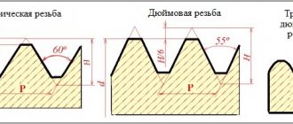
This parameter is determined by the design features of the manufactured part, assembly or assembly as a whole. The chamfer angle is determined by accepted standards and specifications. The value of this indicator depends on the selected material and the purpose of the specific structural element. For metal products, the state standard establishes the following values:
- metal sheets - 45°;
- pipes and cylindrical products 37.5°.
In accordance with the requirements of GOST, the possible value of the chamfer leg size is determined. The value of this parameter varies from 0.1 mm to 250 mm depending on the shape and size of the part.
For structures made of wood or synthetic materials, the angle values are determined by the requirements for a particular product. They are specified in the design documentation, where the minimum and maximum angle values and leg size are set.
How to determine the pitch of an inch thread?
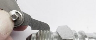
To understand whether the pitch size of inch cutting meets the requirements of GOST, you need to take measurements. You will need a template and tools. Any fitting can be used as a template, the step size of which exactly corresponds to the technical documentation. A bolt, the cutting pitch of which is measured, is screwed into the selected element. If the connection is tight, the notch pitch complies with GOST requirements.
You can determine the pitch of an inch thread using a thread gauge.
If the connection is loose or the bolt does not fit, the measurement is carried out with a thread gauge. The plate is tightly applied to the thread - a tight fit will indicate that the notches correspond to the size indicated on the body.
Types of chamfers
This type of processing refers to the resulting surface shape. It is cut in several ways. These methods are designated by the Latin letters “Y”, “X” and “J”. In some literature and reference books on metalworking you can find other designations “V”, “K”, and “U”. These designations indicate the method for obtaining the required cut.
The most common are the first two methods. These types of chamfers are produced using standard metal-cutting tools on various processing machines: turning, milling, combined, CNC machines.
They also obtain chamfers for threads according to GOST. Currently, developed methods and equipment make it possible to obtain standard chamfer sizes.
In most cases, the procedure and rules for obtaining chamfers, geometric dimensions, and rules for drawing on drawings are determined by the established GOST 10549-80.
Download GOST 10549-80
It sets valid values for the following parameters:
- thread run parameters;
- permissible undercut dimensions;
- the size of the permitted grooves at the outlet of the thread cutting tool used;
- chamfer sizes depending on the diameter and type of thread applied (metric or inch, pipe, conical, trapezoidal);
- For external threads, the run-off and undercut dimensions are established.
To obtain a more complex type of chamfer “J”, special chamfer removers are used. This type is most often used during preparatory work before welding. Thanks to this shape, a larger volume weld pool is obtained, which helps to obtain a stronger and higher-quality seam.
In some cases, other individual edge cutting forms are used. In this case, the procedure for their implementation is given in other standards or technical specifications. For example, Standard No. 5264 of 1980 provides rules for making a joint with a broken bevel.
Legend
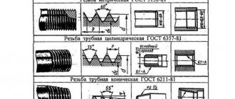
The above state standard GOST 6357-81 establishes the following designations for pipe inch threads:
- name: letter G for cylindrical and R (designation according to GOST 6211) for conical;
- dimensions in inches;
- designation of the direction of the threaded thread, the left one is supplemented with the letters LH;
- accuracy class: A or B;
- make-up length in millimeters.
Example G 1 1/4 LH - A - 36.
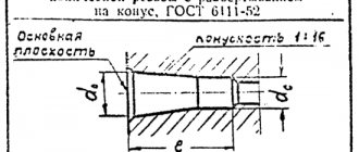
The symbol for conical types according to GOST 6111-52 includes their name (letter K) and standard size in inches, for example: K 1 1/4.
Rice. 9 Parameters of tapered 60° NPT threads
Manufacturing methods
The methods used to make edges depend on the following conditions:
- purpose of the chamfer being prepared;
- the material from which the structural element is made;
- the equipment used.
According to the method used, the following types of edge preparation are distinguished:
- mechanical cutting;
- oxygen gas;
- air-plasma.
To cut bevels on metal products, various metalworking equipment equipped with special tools is used. With its help you can obtain the required chamfer size for the thread. The use of special cutters and milling tools allows chamfering of holes.
Particular attention is paid to preparing the edges of the transition from one shaft diameter to another. This transition is called a fillet. It is quite common in mechanical engineering. The design of fillets with shafts is carried out in various ways in compliance with established standards.
As already noted, special chamfer removers are used for more accurate edge removal. They allow you to obtain a given angle and leg length.
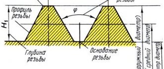
What is pipe thread
A thread is a groove that is applied mechanically or manually. It is characterized by the special height and relief of the spiral groove, its shape, the distance between the turns - the pitch. The thread can be applied to both the external and internal surface of the pipe. In addition, it may be present on a metal rod or conical surface.
The main purpose of pipe threads is to connect parts of the system. For a successful and tight connection, it is necessary that the grooves on both parts are identical in relief, pitch and shape. Moreover, they must be located on different surfaces - one inside, the other outside the pipe.
For reference: the above does not mean that the cutting can only be for fastening. Another type is the chassis. The latter is used in machine parts, where it is necessary not only to connect, but also to ensure the free movement of elements.
Basic terms
Let's take a closer look at the basic terms and concepts that define bearing fits. Modern mechanical engineering is based on the principle of interchangeability. Any part made according to one drawing must be installed in the mechanism, perform its functions, and be interchangeable.
To do this, the drawing determines not only the dimensions, but also the maximum and minimum deviations from them, that is, tolerances. Tolerance values are standardized by a unified system for tolerances, ESDP landings, divided into degrees of accuracy (qualities), and are given in tables.
They can also be found in the first volume of the Anuriev Mechanical Designer's Handbook, and GOSTs 25346-89, as well as 25347-82 or 25348-82.
According to GOST 25346-89, 20 accuracy grades are defined, but in mechanical engineering they are usually used from 6 to 16. Moreover, the lower the quality number, the higher the accuracy. For landings of ball and roller bearings, 6.7, less often 8 qualifications are relevant.
Within the same qualification, the tolerance size is the same. But the upper and lower deviation of the size from the nominal value are located differently and their combinations on the shafts and holes form different fits.
There are fits that guarantee clearance, interference, and transitional fits that implement both minimum clearance and minimum interference. Landings are designated by Latin lowercase letters for shafts, large ones for holes, and a number indicating quality, that is, the degree of accuracy. Landing designations:
- with clearance a, b, c, d, e, f, g, h;
- transitional js, k, m, n;
- with interference p, r, s, t, u, x, z.