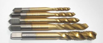
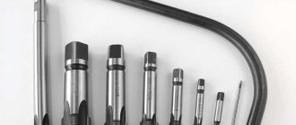
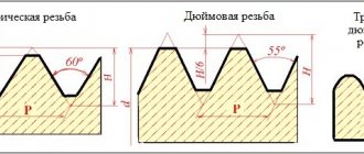
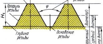
Despite the simplicity of cutting internal threads in comparison with many other metal-cutting operations, which can be easily performed with a minimum set of tools at home, some requirements must be met to obtain a reliable connection. One of these requirements is the exact selection of the hole diameter to the nominal size of the metric thread. If it is lower than required, then there is a risk of breaking the tap; if it is higher, then there will be a weakening of the threaded connection, deformation of the threads and failure of the part. Let's consider the features of selecting a drill for the diameter of metric threads.
Hole parameters
The following thread parameters are distinguished:
- diameters (internal, external, etc.);
- profile shape, height and angle;
- step and entry;
- others.
The condition for connecting parts to each other is the complete coincidence of the external and internal threads. If any of them are not performed in accordance with the requirements, the fastening will be unreliable.
External thread
The fastening can be bolted or stud, which, in addition to the main parts, includes nuts and washers. Before joining, holes are formed in the parts to be fastened, and then cutting is carried out.
To perform it with maximum accuracy, you should first form a hole by drilling, equal to the size of the internal diameter, that is, formed by the tops of the protrusions.
When performing a through design, the diameter of the hole must be 5-10% larger than the size of the bolt or stud, then the following condition is met:
dresponse = (1.05..1.10)×d, (1),
where d is the nominal diameter of the bolt or stud, mm.
To determine the hole size of the second part, the calculation is carried out as follows: the pitch value (P) is subtracted from the value of the nominal diameter (d) - the resulting result is the desired value:
dresponse = d - P, (2).
The calculation results are clearly demonstrated by the table of threaded hole diameters, compiled according to GOST 19257-73, for sizes 1-1.8 mm with small and main pitches.
| Hole size, mm | ||
| 1 | 0,2 | 0,8 |
| 1 | 0,25 | 0,75 |
| 1,1 | 0,2 | 0,9 |
| 1,1 | 0,25 | 0,85 |
| 1,2 | 0,2 | 1 |
| 1,2 | 0,25 | 0,95 |
| 1,4 | 0,2 | 1,2 |
| 1,4 | 0,3 | 1,1 |
| 1,6 | 0,2 | 1,4 |
| 1,6 | 0,35 | 1,25 |
| 1,8 | 0,2 | 1,6 |
| 1,8 | 0,35 | 1,45 |
An important parameter is the drilling depth, which is calculated from the sum of the following indicators:
- screw-in depth;
- reserve of external thread of the screwed-in part;
- her undercut;
- chamfers.
In this case, the last 3 parameters are for reference, and the first is calculated through the coefficients for taking into account the material of the product, which are equal for products from:
- steel, brass, bronze, titanium – 1;
- gray and ductile cast iron – 1.25;
- light alloys – 2.
Internal thread on barrel coupling
Thus, the screw-in depth is the product of the material factor and the nominal diameter, and is expressed in millimeters.
Download GOST 19257-73
This is interesting: Wire bending: manually and on wire bending machines
The old-fashioned way: how to choose a drill for a tap
Good afternoon, dear readers!
I don’t know if you have ever encountered such a tool as a tap. But, if you work with fasteners, then sooner or later you will encounter this. Even if you are not a builder, you can experience the usefulness of this tool.
So, let's ask Wikipedia: what is a tap?
Metchik
- a tool for cutting internal threads, is a screw with cut straight or helical chip grooves that form cutting edges.
That is, the convenience is that you can drill a hole in the metal and cut a thread there, so that you can then screw in the threaded fasteners.
However, while taps are strong, they are not designed to make a hole. Therefore, you first need to make a hole
.
And here the difficulty lies in the fact that it is important not to make a mistake in the diameter of the drill
.
If you make the hole larger, the thread will turn out small and will quickly become beveled (or there will be no room for the thread at all), if you make it smaller, the tap will lock. And that is not all. The thread pitch on taps can be different, so each step will have its own drill diameter
.
Constantly carrying a table with you that indicates the required drill diameters is also not always convenient. Therefore, I offer you the old-fashioned way of how to select a drill for a tap
!
To make it more clear, let's look at an example:
- So you purchased bolts with a basic metric pitch of M8
.
Their pitch is: 1.25
. - Now you need to take a tap 8*1.25
. - Subtracts the second value from the first
: 8-1.25.
It turns out 6.75
. - But there are no 6.75 drills, so we round up
half
a millimeter .
It turns out 6.8
. - It turns out that in order to successfully cut a thread for 8*1.25
, you need to use
a 6.8 mm drill
.
Everything is extremely simple!
If you liked the article, then like it! And for those who have not yet subscribed to the channel, I recommend subscribing, because there is still a lot of useful information ahead!
Source: zen.yandex.ru
Types and parameters of thread
The parameters by which threads are divided into different types are:
- units of diameter (metric, inch, etc.);
- number of thread starts (one-, two- or three-thread);
- the shape in which the profile elements are made (triangular, rectangular, round, trapezoidal);
- direction of rise of turns (right or left);
- location on the product (external or internal);
- surface shape (cylindrical or conical);
- purpose (fastening, fastening and sealing, chassis).
Metric thread parameters
Depending on the above parameters, the following types of thread are distinguished:
- cylindrical, which is designated by the letters MJ;
- metric and conical, designated M and MK respectively;
- pipe, designated by the letters G and R;
- with a round profile, named after Edison and marked with the letter E;
- trapezoidal, designated Tr;
- round, used for installation of sanitary fittings, – Kr;
- thrust and thrust reinforced, marked as S and S45, respectively;
- inch thread, which can also be cylindrical and conical - BSW, UTS, NPT;
- used to connect pipes installed in oil wells.
Thread types according to GOST
Holes for cutting metric threads. Diameters
| Designation: | GOST 19257-73 |
| Status: | active |
| Type: | GOST |
| Russian name: | Holes for cutting metric threads. Diameters |
| English name: | Holes for threading metric thread. Diameters |
| Date of text update: | 06.04.2015 |
| Description update date: | 01.06.2019 |
| Publication date: | 01.12.2002 |
| Effective date: | 01.01.1974 |
| Last modified date: | 12.09.2018 |
| Reissue: | reissue |
| Area and conditions of application: | This standard establishes the diameters of holes that provide cutting metric threads with tolerances in gray cast iron, in steels, in aluminum cast alloys, in copper |
| Instead: | MN 5384-64 MN 5385-64 |
| Is located in: | All-Russian Classifier of Standards → Mechanical systems and devices for general purposes → Screw threads → Metric threads Classifier of state standards → Machinery, equipment and tools → General parts and machine components → Threads |
How to use the filter on the website to select a drill bit for threading?
In the Metal Drills section, a filter with the “For thread” parameter has been implemented, thanks to which you can find the desired drill in literally 2 mouse clicks:
- Choosing a thread.
- Click “Apply”.
- We get suitable drills.
For which materials are the values indicated in the table?
The indicated hole diameters provide cutting of metric threads in:
- gray cast iron
- carbon steels of ordinary quality
- quality structural steels
- alloyed structural steels
- high alloy steels
- corrosion-resistant, heat-resistant and heat-resistant alloys
- heat-resistant steels
- aluminum casting alloys
- copper
A complete list of threads and diameters can be found in GOST 19257-73 - an official technical document with all the nuances and details.
Before you get started, we recommend that you read the practical tips in the article How to properly cut a thread with a tap. And there you can find suitable coolant for different materials.
Source: sverla.info
Cutting technique
Using a hand tap, cutting can be carried out following the following steps:
- drill an opening for a thread of the appropriate diameter and depth;
- countersink it;
- secure the tap in the holder or driver;
- align it perpendicular to the working cavity in which cutting will be carried out;
- screw the tap with light pressure clockwise into the hole prepared in advance for threading;
- Turn the tap back every half turn to cut off the chips.
Thread system
To cool and lubricate surfaces during the cutting process, it is important to use lubricants: machine oil, drying oil, kerosene and the like. Incorrectly selected lubricant can lead to poor cutting results.
Metal for making
For various types of dies, taps, and other metal-cutting tools, carbon steels of popular grades U10A and U12A are used. They are hardened to obtain a hardness of HRC 60-62 units. This indicator makes them the most resistant when cutting metal and other hard materials.
Read also: Drawing with a wood router
Much better red-hardness indicators are found in tool steel with the addition of alloying elements:
Metal-cutting tools made from a similar material, for example, a die for cutting threads or a broach tap, have higher cutting properties. Machinability is much better than carbon steels. Red resistance with alloying additives also has excellent performance.
Selecting drill size
The diameter of the drill for a hole for a metric thread is also determined by formula (2), taking into account its main parameters.
It is worth noting that when cutting in ductile materials, such as steel or brass, the turns increase, so it is necessary to choose a larger drill diameter for the thread than for brittle materials, such as cast iron or bronze.
In practice, drill sizes are usually slightly smaller than the required hole. Thus, Table 2 shows the ratio of the nominal and outer thread diameters, the pitch, the diameters of the hole and the drill for cutting metric threads.
Table 2. The relationship between the main parameters of metric threads with normal pitch and the diameters of the hole and drill
| Nominal diameter, mm | Outer diameter, mm | Pitch, mm | Largest hole diameter, mm | Drill diameter, mm |
| 1 | 0,97 | 0,25 | 0,785 | 0,75 |
| 2 | 1,94 | 0,4 | 1,679 | 1,60 |
| 3 | 2,92 | 0,5 | 2,559 | 2,50 |
| 4 | 3,91 | 0,7 | 3,422 | 3,30 |
| 5 | 4,9 | 0,8 | 4,334 | 4,20 |
| 6 | 5,88 | 1,0 | 5,153 | 5,00 |
| 7 | 6,88 | 1,0 | 6,153 | 6,00 |
| 8 | 7,87 | 1,25 | 6,912 | 6,80 |
| 9 | 8,87 | 1,25 | 7,912 | 7,80 |
| 10 | 9,95 | 1,5 | 8,676 | 8,50 |
As can be seen from the table, there is a certain dimensional limit, which is calculated taking into account thread tolerances.
The size of the drill is much smaller than the hole. So, for example, for an M6 thread, the outer diameter of which is 5.88 mm, and its largest hole value should not exceed 5.153 mm, you should use a 5 mm drill.
A hole for an M8 thread with an outer diameter of 7.87 mm will be only 6.912 mm, which means the drill for it will be 6.8 mm.
The quality of the thread depends on many factors when cutting it: from the choice of tool to the correctly calculated and prepared hole. Too little will lead to increased roughness and even breakage of the tap. Large forces applied to the tap contribute to non-compliance with tolerances and, as a result, dimensions are not maintained.
This is interesting: How to drill stainless steel at home: video, photos, tips
Internal thread cutting technology
As mentioned above, before starting work, you need to drill a hole, the diameter of which must exactly fit a thread of a certain size. It should be borne in mind: if the diameters of the holes intended for cutting metric threads are chosen incorrectly, this can lead not only to poor quality execution, but also to breakage of the tap.
Considering the fact that the tap, when forming threaded grooves, not only cuts the metal, but also pushes it, the diameter of the drill for making threads should be slightly smaller than its nominal diameter. For example, a drill for making M3 threads should have a diameter of 2.5 mm, for M4 - 3.3 mm, for M5 you should choose a drill with a diameter of 4.2 mm, for M6 threads - 5 mm, M8 - 6.7 mm, M10 - 8.5 mm, and for M12 - 10.2.
Table 1. Main diameters of holes for metric threads
Table 2. Diameters of holes for inch threads
All diameters of drills for GOST threads are given in special tables. Such tables indicate the diameters of drills for making threads with both standard and reduced pitches, but it should be borne in mind that holes of different diameters are drilled for these purposes. In addition, if threads are cut in products made of brittle metals (such as cast iron), the diameter of the thread drill obtained from the table must be reduced by one tenth of a millimeter.
You can familiarize yourself with the provisions of GOST regulating the cutting of metric threads by downloading the document in pdf format from the link below.
The diameters of drills for metric threads can be calculated independently. From the diameter of the thread that needs to be cut, it is necessary to subtract the value of its pitch. The thread pitch itself, the size of which is used when performing such calculations, can be found out from special correspondence tables. In order to determine what diameter the hole needs to be made using a drill if a three-start tap is used for threading, you must use the following formula:
To = Dm x 0.8, where:
Do is the diameter of the hole that must be made using a drill,
Dm is the diameter of the tap that will be used to process the drilled element.
Scheme of cutting internal threads with a tap
The drivers into which the threaded tap is inserted can have a simple design or be equipped with a ratchet. You should work with such devices with tools fixed in them very carefully. To obtain high-quality and clean threads, rotating the tap clockwise, performed half a turn, must be alternated with turning it one-fourth of a turn against the thread.
The thread will be cut much easier if you use a lubricant during this procedure. The role of such a lubricant when cutting threads in steel products can be played by drying oil, and when processing aluminum alloys - alcohol, turpentine or kerosene. If such technical fluids are not at hand, then ordinary machine oil can be used to lubricate the tap and the thread being cut (however, it has less effect than the substances listed above).
Source: met-all.org
Adaptations
Manual or automatic cutting methods provide results in various classes of accuracy and roughness. Thus, the main tool remains a tap, which is a rod with cutting edges.
Tap device
Taps are:
- manual, for metric (M1-M68), inch - ¼-2
ʺ, pipe – 1/8-2
ʺ
;
- machine-manual - attachments for drilling and other machines, used for the same sizes as manual ones;
- nuts, which allow you to cut a through version for thin parts, with nominal sizes of 2-33 mm.
- For cutting metric threads, use a set of rods - taps:
- rough, having an elongated intake part, consisting of 6-8 turns, and marked with one mark at the base of the shank;
- medium - with a fence of average length of 3.5-5 turns, and markings in the form of two marks;
- the finishing part has a fence of only 2-3 turns, without marks.
Tolerance control of metric thread placement
When cutting manually, if the pitch exceeds 3 mm, then use 3 taps. If the product pitch is less than 3 mm, two are enough: roughing and finishing.
Taps used for small metric threads (M1-M6) have 3 grooves that carry chips and a reinforced shank. The design of the others has 4 grooves, and the shank is through.
The diameters of all three rods for metric threads increase from rough to finish. The last threaded rod must have a diameter equal to its nominal diameter.
The taps are attached to special devices - a tool holder (if it is small) or a crank. They are used to screw the cutting rod into the hole.
Preparing holes for cutting is carried out using drills, countersinks and lathes. It is formed by drilling, and by countersinking and boring it is increased in width and improves the quality of the surface. The fixtures are used for cylindrical and conical shapes.
Thread pitch
A drill is a metal rod consisting of a cylindrical shank and a helical cutting edge. Their main geometric parameters include:
- the helical lift angle is usually 27°;
- point angle, which can be 118° or 135°.
Drills are rolled, dark blued, and shiny - ground.
Countersinks for cylindrical shapes are called counterbores. They are metal rods with two cutters twisted into a spiral and a fixed guide pin to insert the countersink into the cavity.
Taps for threading: types, size tables, GOST requirements
You can make a thread in a finished metal hole or nut in literally seconds if you have a tap. Using this metal-cutting tool, you can apply internal threads and calibrate existing ones.
Of course, taps are not the only tool used to create threads. For example, dies and blanks fall into a similar category. They are used to apply threads to the outside of a part. But that’s not about that now.
There are quite a few types of taps; experienced craftsmen have never even heard of some of them. Therefore, we will leave the specific types of this tool to highly specialized specialists and analyze the most popular ones.
Let's try to choose a tool for specific needs. Using the algorithm presented below, this will not be difficult to do.
Step 1. Application areas: home workshop or production
Obviously, when working at home and in production, the master will need different tools.
Hand taps
(they are also locksmiths) can be found in any workshop. Due to its significant strength and wear resistance, the tool allows you to perform high-precision work even in domestic conditions. They are usually equipped with a special crank necessary to rotate the tap.
Hand taps are almost always sold in sets of 2-3 pieces of various diameters. Each tool performs its task: one performs rough thread processing, the second (if any) does intermediate processing, the third does finishing, after which the profile meets all GOST standards (more on them below).
But hand taps are not designed to operate at high rotation speeds. For this, machine analogues are used.
Machine taps
Made from higher quality high-speed steel, which can easily withstand the severe heat that occurs due to friction and cutting metal. It is in terms of strength that metalworking taps are inferior to their machine counterparts. In addition, machine tools have a small intake part, because The alignment of the tap and the workpiece hole is ensured by the design of the machine.
There is also a third type of taps - nut
. It is easy to guess that they are used exclusively for threading nuts.
Nut taps have a long shank, which is installed in a special automatic machine. After the threads are applied, the nuts are moved one by one to the tail section and wait there until the entire series is completed. The tap is then removed from the chuck and all nuts are dumped into the receiving tray. This significantly saves operating time and increases productivity.
Step 2. Hole type: blind or through
The purpose of your work is of no small importance: are you going to create a profile in a blind hole or a through hole? Depending on this, you will need different tools. In particular, the chip flutes on the tap will play an important role. They can twist (both to the left and to the right), or they can be positioned straight.
Straight-line
grooves are used in universal taps.
Tools with right groove recess
More often used to create a profile in blind holes. Along these grooves, the chips are squeezed back outward and do not clog the hole.
Left-directed helical grooves
used to create a profile in through holes. The chips are forced out directly in front of the tap, thereby protecting the newly applied threads from damage.
There is also an option for taps with shorter flutes, known as fluteless taps.
, or raskatniki. This design helps create threads in products made from ductile materials, for example, alloyed high-strength and low-carbon ductile steels, as well as aluminum alloys.
Step 3: Thread Type
In production, there are several state standards that differ in the measurement system. Using the markings on the tap, you can understand which of them the tool belongs to - metric or inch. Based on the type of tap device, three types of threads can be applied.
Metric thread
Metric taps are useful for creating a profile whose dimensions are measured in millimeters. They are marked with the symbol “M”.
The profile of taps of this type is an isosceles triangle with an apex angle of 60°.
The size range of metric taps is quite extensive - with their help you can create almost any profile. Each tap size has its own main pitch - the distance between the threads. The larger the size, the larger the main step. To select a tool, a special table is used based on state standards (according to GOST 19257-73).
Inch thread
Unlike metric ones, the size of inch taps is indicated in inches. This system came to us from abroad. In particular, from the USA and Great Britain.
The main pitch is indicated by the number of threads (or number of turns) per 1 inch. The higher the number, the finer the thread pitch.
The vertex angle in inch threads can be different. The 60° angle is typical for taps common in North America. UNC thread has gained maximum popularity. Such fasteners are often found on equipment imported to Russia (lawn mowers, generators, cultivators, etc.).
British standard BSW inch threads have a tip angle of 55°.
Below are the inch sizes of taps of the most popular standards.
Pipe thread
Among inch taps, it is worth highlighting a group of tools used to create a profile in pipe connections. Pipe threads are especially common in elements of water supply systems.
The dimensions of the pipe taps are specially adjusted to standard types of metal pipes. They are divided into cylindrical
and
conical
. The first ones are designated by the letter “G”, followed by a number corresponding to the bore diameter. Tapered pipe taps are marked with the symbols “R” or “Rc”. The thread is applied to the surface with a taper of 1:16 and reaches the stop.
Traditionally, their sizes are indicated in inches. However, over time, the designation system has lost its identity with the actual dimensions, so tools for pipe threads are selected according to tables (based on GOST 6357-81 and GOST 6111-81).
GOST requirements
State standards determine the requirements for the dimensions and characteristics of taps, and also introduce maximum tolerances, accuracy class and degree of surface roughness. Almost all indicators for the choice and quality of threads are regulated by GOST 3266-81, which you can.
Using taps
In actual practice, in production, as well as in various workshops, taps are most often used. They implement the principle of sequential introduction of cutting edges into the body of the workpiece. But there is more than one row of teeth, like a comb. A powerful body is used that is capable of centering the tool inside the hole.
Tap:
a) structural elements: 1 – thread of the threaded part; 2 – square shank for transmitting torque; 3 – cylindrical part of the shank; 4 – groove for collecting chips; 5 – cutting edges (feathers); b) geometric parameters of the cutting part: 1 – front surface facing the part; 2 – cutting edge, triangular teeth; 3 – backed part, rear surface; 4 – reverse part, forming a support; 5 – feather; α – rear angle of the backed part; β – apex angle, it is also called the cutting angle; δ – angle of sharpening of the edges of the cutting blade (triangle); γ – front angle facing the material being removed; c) a tap with a straight chip flute: 1 – groove for collecting chips; d) a tap having a helical flute. Typically found on machine tools with pressurized coolant; e) for cutting blind threads on machines
The choice of one design or another is determined by the characteristics of the process. Most craftsmen use taps with straight flutes in their arsenal. After completing one pass, the tool is removed. Chips and other inclusions that may end up in the hole are removed from it.
One pass does not cut the thread completely. Typically, roughing and finishing taps are used.
Types of thread taps
A crank is used to rotate the tap located in the hole. The design can be very diverse.
Types of cranks for manual tapping of holes
Sequence of tool use
Most often, the kit includes two taps. But to obtain high-quality threads, kits that include three tools can also be used. Some manufacturers, in addition to the parameters of the thread being cut, indicate the letters: A, B, C. Others apply several marks:
- 1 risk on draft;
- 2 risks on the main;
- 3 risks on finishing.
In addition to external designations, the type of tap can be distinguished by a number of characteristics:
- The first pass roughing tool has a minimum diameter. It is enough to measure the outer size using a caliper to find it in the set. The part that goes in first has fine teeth, the tops are cut almost to nothing;
- the second tap in the set has noticeably longer feather combs. The diameter value will be the average of the three. The last teeth will cut the full profile thread;
- In a finishing tap, almost all teeth have the same height. The closing ones do not cut, but calibrate the formed screw grooves in the hole.
General view of the taps from the set
Application of the tap
Before you start threading, you need to determine the diameter of the preparation hole and drill it. To facilitate this task, a corresponding GOST was developed, which contains tables that allow you to accurately determine the diameter of the threaded hole. This information makes it easy to select the drill size.
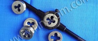
To cut metric threads on the inner walls of a hole made with a drill, a tap is used - a screw-shaped tool with cutting grooves, made in the form of a rod, which can have a cylindrical or conical shape. On its side surface there are special grooves located along its axis and dividing the working part into separate segments, which are called combs. The sharp edges of the combs are precisely the working surfaces of the tap.
Tap: design and parameters
In order for the turns of the internal thread to be clean and neat, and for its geometric parameters to correspond to the required values, it must be cut gradually, by gradually removing thin layers of metal from the surface being treated. That is why for this purpose they use either taps, the working part of which is divided along the length into sections with different geometric parameters, or sets of such tools. Single taps, the working part of which has the same geometric parameters along its entire length, are needed in cases where it is necessary to restore the parameters of an existing thread.
The minimum set with which you can sufficiently perform machining of threaded holes is a set consisting of two taps - rough and finishing. The first one cuts a thin layer of metal from the walls of the hole for cutting metric threads and forms a shallow groove on them, the second one not only deepens the formed groove, but also cleans it.
Types of thread taps and their differences
Minimum set of taps
Combination two-pass taps or sets consisting of two tools are used for tapping small diameter holes (up to 3 mm). To machine holes for larger metric threads, you must use a combination three-pass tool or a set of three taps.
To manipulate the tap, a special device is used - a wrench. The main parameter of such devices, which can have different designs, is the size of the mounting hole, which must exactly match the size of the tool shank.
Some types of tap drivers
When using a set of three taps that differ both in their design and geometric parameters, the sequence of their use must be strictly observed. They can be distinguished from each other both by special marks applied to the shanks and by design features.
- The tap, with which the hole for cutting metric threads is processed first, has the smallest diameter among all the tools in the set and cutting teeth, the upper part of which is heavily cut off.
- The second tap has a shorter fence and longer combs. Its working diameter is intermediate between the diameters of the other tools in the set.
- The third tap, with which the hole for cutting metric threads is processed last, is characterized by full ridges of cutting teeth and a diameter that must exactly match the size of the thread being formed.
Set of three taps
Taps are used primarily for cutting metric threads. Much less often than metric ones, taps designed for processing the internal walls of pipes are used. In accordance with their purpose, they are called pipe, and they can be distinguished by the letter G present in their markings.
Combination tool
In addition to conventional taps and drills, special combinations are used in practice. With their help, the hole is drilled to the desired size. The same device cuts threads. For light alloys, as well as low-carbon steel, such devices are used not only by craftsmen in their own workshops. They are used in large enterprises where various products have to be mass-produced.
Combination tap-drill
A similar tool is used when it is necessary to slightly increase the diameter of workpieces. Similar operations often have to be performed when working with castings. There are already holes there, obtained through core mixtures. But they often do not have the required shape and size. By using a tap-drill, two operations will be performed at once.
The widespread use of electric screwdrivers in production and at home has led to the creation of special drill taps for this convenient tool. You can purchase entire sets.
Drill bit for screwdriver
Manufacturers write that such products are best used for plastics and aluminum alloys. In fact, if lubricated, such tools do a good job on low-carbon structural steels.
At most large enterprises, the thread cutting procedure is as mechanized as possible. Special machine taps are used. They are distinguished by a long shank, as well as the presence of not only cutting combs. There is also a calibrating part.
Video: how to choose a drill for tapping?
How to make carvings using a die
A pipe threading die, a wrench and a pipe clamp are tools that are required when working with piping systems. To select a left-handed/right-handed die, evaluate the markings. If there is a letter designation LH, you have a tool for left-hand thread.
Photo No. 5: The process of cutting threads on a workpiece
After the preparatory issues have been resolved, proceed to processing the workpiece. To do this, go over the part with a file and lubricate the joint with oil. Next, insert the tool into the driver and the workpiece into the clamp. Place the die on the product and perform several turns at the rate of 2-3 in the desired direction, half a turn in the opposite direction. During operation, the tool must be positioned perpendicular to the workpiece.
To achieve maximum thread accuracy, use a split-type die. This tool has locking screws, which allows you to control the diameter of the thread while cutting it.
Read also: Stepper motor 6 wires connection
A thread tap is a tool used to create permanent connections. Manufactured in the form of a screw rod. Its shape can be cylindrical, conical, uterine, in the form of a die - these are the main types of taps existing in mechanics. The shapes depend on the type of thread being cut. Either three or four grooves are made on the longitudinal sides of the rod.
Table of drill diameters for cutting metal threads with a tap and driver
The hole depends not only on the section, but also on the pitch. We offer data for large and small cutting:
| Spiral, mm | Pitch coarse, mm | Drill, mm | Small, mm | Circumference, mm |
| 2 | 0,4 | 1,6 | 0,25 | 1,75 |
| 6 | 1 | 5 | 0,5 | 5,5 |
| 10 | 1,5 | 8,5 | 0,5 | 9,5 |
| 14 | 2 | 12 | 0,5 | 13,5 |
| 18 | 2,5 | 15,4 | 0,5 | 17,5 |
| 22 | 2,5 | 19,4 | 0,5 | 21,5 |
| 30 | 3,5 | 26,4 | 0,75 | 29,2 |
| 36 | 4 | 31,9 | 1 | 35 |
| 42 | 1,5 | 37,4 | 1 | 41 |
| 48 | 5 | 42,8 | 1 | 47 |
Diameter of threaded drill (table)
The main thread pitch is highlighted in color
Download the table “Drill diameter for metric threads”
| Metric thread, M | |||
| Tap | Drill | Tap | Drill |
| M1.4x0.3 | 1.1 | M14x1.25 | 12.8 |
| M1.6x0.35 | 1.25 | M14x1 | 13 |
| M2x0.4 | 1.6 | M16x2 | 14 |
| M2.5x0.45 | 2.05 | M16x1.5 | 14.5 |
| M3x0.5 | 2.5 | M16x1.25 | 14.8 |
| M3.5x0.6 | 2.9 | M16x1 | 15 |
| M4x0.7 | 3.3 | M18x2.5 | 15.5 |
| M4x0.5 | 3.5 | M18x2 | 16 |
| M5x0.8 | 4.2 | M18x1.5 | 16.5 |
| M5x0.5 | 4.5 | M18x1 | 17 |
| M6x1 | 5 | M20x2.5 | 17.5 |
| M6x0.5 | 5.5 | M20x2 | 18 |
| M7x1 | 6 | M20x1.5 | 18.5 |
| M7x0.5 | 6.5 | M22x2.5 | 19.5 |
| M8x1.25 | 6.8 | M22x2 | 20 |
| M8x1 | 7 | M22x1.5 | 20.5 |
| M8x0.75 | 7.2 | M24x3 | 21 |
| M8x0.5 | 7.5 | M24x2 | 22 |
| M9x1.25 | 7.8 | M24x1.5 | 22.5 |
| M9x1 | 8 | M27x3 | 24 |
| M10x1.5 | 8.5 | M27x2 | 25 |
| M10x1.25 | 8.8 | M27x1.5 | 25.5 |
| M10x1 | 9 | M30x3.5 | 26.5 |
| M11x1.5 | 9.5 | M30x3 | 27 |
| M11x1.25 | 9.8 | M30x2 | 28 |
| M11x1 | 10 | M30x1.5 | 28.5 |
| M12x1.75 | 10.2 | M33x3.5 | 29.5 |
| M12x1.5 | 10.5 | M33x3 | 30 |
| M12x1.25 | 10.8 | M33x2 | 31 |
| M12x1 | 11 | M33x1.5 | 31.5 |
| M14x2 | 12 | M36x4 | 32 |
| M14x1.5 | 12.5 | M42x4.5 | 37.5 |
| Pipe thread, G | |||
| Tap | Drill | Tap | Drill |
| G 1/8 | 8.8 | G 1 1/4 | 39.5 |
| G 1/4 | 11.8 | G 1 3/8 | 42 |
| G 3/8 | 15.25 | G 1 1/2 | 45.5 |
| G 1/2 | 19 | G 2 | 57.5 |
| G 5/8 | 21 | G 2 1/4 | 63.5 |
| G 3/4 | 24.5 | G 2 1/2 | 72.5 |
| G 7/8 | 28.25 | G 2 3/4 | 78.5 |
| G 1 | 30.75 | G 3 | 85.5 |
| G 1 1/8 | 35.5 | ||
| Inch UNC thread | |||
| 1/4x20 | 5.1 | 7/8x9 | 19.5 |
| 5/16x18 | 6.5 | 1x8 | 22.25 |
| 3/8x16 | 8 | 1 1/8x7 | 25 |
| 7/16x14 | 9.4 | 1 1/4x7 | 28.25 |
| 1/2x13 | 10.8 | 1 3/8x6 | 30.75 |
| 9/16x12 | 12.2 | 1 1/2x6 | 34 |
| 5/8x11 | 13.6 | 1 3/4x5 | 39.5 |
| 3/4x10 | 16.5 | 2x4 | 45 |
| Inch fine thread UNF | |||
| 1/4x28 | 5.5 | 3/4x16 | 17.5 |
| 5/16x24 | 6.9 | 7/8x14 | 20.5 |
| 3/8x24 | 8.5 | 1x12 | 23.25 |
| 7/16x20 | 9.9 | 1 1/8x12 | 26.5 |
| 1/2x20 | 11.5 | 1 1/4x12 | 29.75 |
| 9/16x18 | 12.9 | 1 3/8x12 | 33 |
| 5/8x18 | 14.5 | 1 1/2x12 | 36 |
| Trapezoidal thread Tr | |||
| Tr 8x1.5 | 6.6 | Tr 14x3 | 11.25 |
| Tr 10x1.5 | 8.6 | Tr 14x4 | 10.25 |
| Tr 10x2 | 8.2 | Tr 16x4 | 12.25 |
| Tr 10x3 | 7.5 | Tr 18x4 | 14.25 |
| Tr 12x2 | 10.2 | Tr 20x4 | 16.25 |
| Tr 12x3 | 9.25 | Tr 22x3 | 19.25 |
| Tr 14x2 | 12.2 | Tr 22x5 | 17.25 |
To cut internal threads with a tap, you first need to drill a hole of a certain diameter. The table shows the most popular threads and drill diameters required for drilling holes for threads.
Table of rod diameters for external threads
There is no strict section for the workpiece; a range is usually offered.
| Spiral, mm | 6 | 8 | 10 | 12 | 14 | 16 | 18 | 20 | 22 | 24 | 27 | 30 |
| Pitch, mm | 1 | 1,25 | 1,5 | 1,75 | 2 | 2 | 2,25 | 2,25 | 2,25 | 3 | 3 | 3,5 |
| Minimum and maximum cross-section of the rod, mm | 5,8 | 7,8 – 7,9 | 9,75 – 9,85 | 11,76 – 11,88 | 13,7 – 13,82 | 15,7 – 15,82 | 17,7– 17,82 | 19,82 – 19,86 | 21,72 – 21,86 | 23,65 – 23, 79 | 26,65 – 26,79 | 29,6 – 29,74 |
Sizes metric and inch
This knowledge will be needed if you have to work not only with domestic markings, but also with foreign ones.
| Spiral circumference in inches | Drill section in mm |
| 1/8 | 8,9 |
| 1/4 | 11,9 |
| 3/8 | 15,8 |
| 1/2 | 19 |
| 2/4 | 24,3 |
| 1 | 30,5 |
| 1,25 | 39,2 |
| 1,75 | 41,6 |
| 1,5 | 45 |
In the article we talked about threaded drills and provided tables. Be careful when choosing the correct sizes.
