- Types of gears
- Gear samples
- Manufacturing materials
- Gear production technologies
- Finishing methods
- Types of machines for making gears
- Made to order
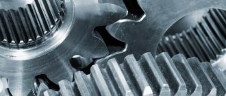
Gears are gears (toothed disks) with a conical or cylindrical surface. They are the most important elements that transmit rotational motion in a gear mechanism. The mandatory condition of having at least six teeth gives the part its name. Typically, gears are used in pairs, since the principle of their operation is based on the alternate reciprocal engagement of the teeth of both wheels with each other. The gear that receives rotational movement from the outside is the driving gear in a pair, the second is the driven one.
The result of the difference in the size of the gear diameters is the acceleration or deceleration of torque. For example, a smaller drive wheel increases the torque of the driven wheel. The number of teeth is also important. The difference in their number in a pair of gears is necessary to convert the shaft speed and output torque. And adding the number of teeth increases the smoothness of the ride.
Types of gears
There is a gradation of gears depending on the material of their production. In mechanisms that experience increased loads, gears made of titanium and steel are installed, the designs of which are resistant to dynamic loads associated with the forced braking of mechanisms of large mass and high counterforce. But it is also possible to combine them in order to save expensive metal. These are prefabricated tire wheels, the inner part of which is, for example, cast iron, and the gear ring is steel.
Types of gears made of non-ferrous metals (aluminum, copper, brass) are applicable in a gas environment due to the absence of spark formation during operation. They are also corrosion-resistant and can operate in dry coupling, without the use of lubricants. The raw materials for the production of gears - iron, steel, cast iron, bronze, softening components - leather, fiber, paper - can be introduced. The cheapest to produce and with the shortest service life are plastic gears. They are often subject to overheating, melting, and deformation.
Gears differ in the depth, direction and shape of the teeth:
Straight teeth
This type of gear is the most popular in production. Its shape is simple; on the round profile of such a gear, the teeth are located strictly parallel to the axis of rotation. Gears with straight teeth are produced by hobbing or casting. The disadvantage of this type of gear is that it can only be connected to elements that are parallel in the same plane. The positive aspects are high efficiency, minimal backlash and low friction and low heating.
Helical
The smooth and quiet operation of such gears is ensured by the location of the teeth at an angle and their increased length. Due to the large contact area, increased friction occurs, which is compensated by the use of lubricant. Also, due to the occurrence of axial mechanical force during the operation of helical gears, the installation of thrust bearings is necessary. Helical type wheels can withstand larger loads and are usually used in mechanisms operating at higher speeds.
Paired helical gears
Here, the problem of axial load is solved by gears with a double set of teeth diverging in different directions. If there is no groove at the junction of the double toothed gear, and the teeth form a V-shape, then the profile pattern of such a gear is called a herringbone.
Internally geared
In units and mechanisms that have a more complex structure, internal gears are used. The teeth in such a gear are located on the inner surface and when it rotates, the counter part rotates in the same direction. This feature ensures a reduction in the number of gears in the mechanism, as well as their unidirectional movement. This type of gear is used in planetary gears and pumps. Also, due to the use of these types of wheels, such mechanisms are smaller in size.
Screw
This type of gearing works in tandem with a pinion or worm gear. The special shape in the form of a long cylinder with teeth ensures precise engagement of such a gear with another gear located perpendicularly. The mechanism, which consists of a pair of such parts, is also compact and easy to use, for example gearboxes where the ability to lower or increase the gear ratio is needed.
Sectoral
Such gears do not carry out the entire rotation, but step-by-step transmission of torque, thanks to teeth partially applied to the width of a certain sector. Being a drive gear, it turns the driven wheel only part of a revolution, continuing further rotation until the next gear. It is the initial part of the mechanism from which rotation begins. This type of wheel is used in packaging equipment, printing and banking equipment.
With circular teeth
Gears with circular teeth are ready to withstand heavy loads and at the same time operate as smoothly as possible. The use of such expensive wheels is possible when ultra-low noise operation of the mechanism and the greatest possible compactness are required. Wheel teeth, bent along a radius and twisted, require special production technology. The disadvantage is the reduced efficiency. Not the most popular type of gears, the use of which is necessary when assembling the most compact mechanism with quiet operation.
Conical
In such a toothed disk, the teeth are straight, oblique, rounded and tangential. The teeth on gears of this type are located along the outer edge. Bevel gears are used with shafts perpendicular to each other to transmit torque at an angle. Often used in mechanisms such as gearboxes and various automotive components, gearboxes. On wheels working in pairs, the number of teeth may differ, this makes it possible to change the gear ratio by increasing or decreasing it.
Racks
The mechanism consists of a rack and a gear; these two parts work in pairs and are counter elements for each other, turning translational motion into rotational motion and vice versa. Such a rack with teeth is an element of a river transmission. Can also work in conjunction with a sector gear. Reiki are produced in various lengths, depending on the mechanism in which it will work.
Stars
This type of gear requires a roller chain to operate. They connect elements and transmit rotation to parts located at some distance from each other. The gear ratio on the drive gear can increase or decrease due to differences in the number of teeth and the diameter of the sprockets. The operation of this type of gear is also ensured by the presence of a toothed rubber belt. When using a belt, no lubrication of parts is required. Another advantage of a timing belt is its low operating noise relative to the use of a chain. As the load increases, the drive belt may slip from the sprocket.
Crowned
Crown gears are not often used in mechanisms, as they are not designed for heavy loads. The name of such gears is due to the lateral arrangement of the teeth, similar to a crown. Crown gears are quite rare and are used when it is necessary to integrate a mechanism into a limited space. Compatible with both spur and bevel gears.
Story
The idea of mechanical transmission itself goes back to the idea of the wheel. By using a system of two wheels of different diameters, it is possible not only to transmit, but also to transform movement. If the driven wheel is a larger one, then at the output we will lose speed, but the torque of this transmission will increase. This gear is useful where you need to “intensify the movement”, for example, when lifting heavy objects. But the clutch between the transmission wheels with a smooth rim is not rigid enough, the wheels slip. Therefore, instead of smooth wheels, gear wheels began to be used.
In ancient Egypt, ox-powered devices consisting of a wooden gear drive and a wheel with a large number of buckets were already used to irrigate land.
Instead of teeth, wooden cylindrical or rectangular fingers were initially used, which were installed along the edge of wooden rims.
Made in the 1st century BC. The Antikythera mechanism consisted of dozens of metal gears.
Gear samples
More
Manufacturing materials
The material for manufacturing is selected depending on its size, the mechanism where it will work and the material of the counter part with which the interaction occurs. Metal gears are used in small mechanisms and large-sized industrial installations, gearboxes, gears, respectively, the load is different and the material is selected based on these parameters.
Gears can be made from materials such as:
- Steel;
- Bronze;
- Brass;
- Duralumin;
- Vtoroplast;
- Caprolon;
- Plastic.
Steel gears are the most wear-resistant and reliable if they are additionally hardened to the required hardness. Steel gears are used in units where there are heavy loads and high rotation speeds of parts. In order for the gears to serve for a long time without breakdowns and sudden failure, it is necessary to carefully monitor the lubricant, such as gear oil, monitor the level and change it in a timely manner. The advantage of steel gears is their resistance to dynamic loads in mechanisms where there is an action such as braking. Steel teeth can easily withstand this type of load.
Gears made of bronze, brass and other types of non-ferrous metals are used where there are no heavy loads on the device. They are ideal for working in aggressive environments, as the non-ferrous metal is resistant to corrosion. The advantage of gears made of non-ferrous metals is low noise and smoother operation. Such parts are usually used in industrial gearboxes, where the worm gear is made of bronze. Gears made of caprolon, vtoroplast or any other type of plastic are less resistant to wear and the teeth grind off faster during operation. This type of gear is not suitable for working with heavy loads and high speeds. At high speeds, rapid heating occurs and the plastic gear begins to melt. But they also have advantages, such as light weight. Plastic is excellent for small gears, for example, they are used in printing equipment, printers, household appliances, and some banking equipment.
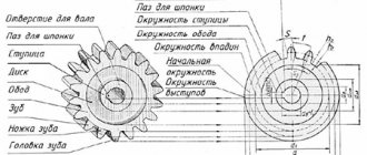
Formula for calculating spur gear parameters
To determine the parameters of a spur gear, you will need to perform some preliminary calculations. The length of the initial circle is π×D, where D is its diameter.
Calculation of gear module
The engagement pitch t is the distance between adjacent teeth measured along the starting circle. If we multiply this distance by the number of teeth z, then we should get its length:
After carrying out the transformation, we get:
If we divide the pitch by pi, we get a factor that is constant for a given gear part. This is called the engagement module m.
The dimension of the gear module is millimeters. If you substitute it into the previous expression, you get:
Having performed the transformation, we find:
This implies the physical meaning of the engagement module: it represents the length of the arc of the initial circle corresponding to one tooth of the wheel. The diameter of the protrusion circle De is equal to
where h' is the height of the head.
The height of the head is equal to m:
Carrying out mathematical transformations with substitution, we get:
The diameter of the circle of the depressions Di corresponds to De minus the two heights of the base of the tooth:
where h“ is the height of the tooth stem.
For cylindrical wheels, h“ is equal to a value of 1.25m:
Gear device
Having performed the substitution on the right side of the equality, we have:
which corresponds to the formula:
and if we perform the substitution, we get:
In other words, the head and stem of the tooth have a height ratio of 1:1.25 to each other.
The next important dimension, tooth thickness s, is taken to be approximately equal to:
- for cast teeth: 1.53m:
- for those made by milling - 1.57m, or 0.5×t
Since the step t is equal to the total thickness of the tooth s and the cavity sв, we obtain formulas for the width of the cavity
- for cast teeth: sв=πm-1.53m=1.61m:
- for those made by milling - sв = πm-1.57m = 1.57m
The design characteristics of the remaining part of the gear part are determined by the following factors:
- forces applied to the part during operation;
- configuration of parts interacting with it.
Detailed methods for calculating these parameters are given in such university courses as “Machine Parts” and others. The gear module is widely used in them as one of the main parameters.
To display gears using engineering graphics methods, simplified formulas are used. In engineering reference books and state standards you can find characteristic values calculated for typical gear sizes.
Gear production technologies
Run-in method. The production of gears in this way is possible using a comb - a tool in the form of a gear rack with a sharpened cutting edge. The comb makes translational or reciprocating movements relative to the workpiece rotating around its axis.
The running-in method is also possible using a cutter shaped like a cutting gear. Since the thickness of the metal does not allow such a process to be carried out in one stage, the cutter makes reciprocating movements relative to the workpiece several times. The method is applicable in the production of internal gears.
It is possible to run in using a hob cutter as a cutting tool, by forming a worm gear with the gear blank. Gear teeth are cut by rotating the hob cutter and the workpiece at a certain angle relative to each other.
The main advantage of the rolling method is the ability to make gears with different tooth shapes with the same tool, changing its position relative to the workpiece on the machine. This technology is more accurate than copying.
Copying (dividing) method. This type of gear production involves cutting the cavities of the gear wheel with a cutting disk or finger cutter, alternately rotating by one angular step. A variation of the technique is stamping and broaching.
Hot and cold rolling. The method is based on thermal layer-by-layer heating of the workpiece and its deformation to cut teeth, followed by rolling to give the shape precision.
Manufacturing of bevel gears. This is the rolling of a workpiece in machine engagement with an imaginary production wheel. As the tool moves, it cuts off the allowance, forming the side surfaces of the gear.
Production of shaft and gears. This assembly mechanism consists of the shaft itself and a gear, the size of the teeth of which is equal to the size of the cavities of the shaft. It is done assembled.
Bevel gears
Main gear in a rear-wheel drive car
In many cars, the implementation of the required movements of the mechanism is associated with the need to transmit rotation from one shaft to another, provided that the axes of these shafts intersect. In such cases, bevel gears are used. There are types of bevel wheels that differ in the shape of the tooth lines: with straight, tangential, circular and curved teeth. Bevel wheels with circular teeth, for example, are used in automobile final drives.
Types of machines for making gears
For reliable engagement and transmission of force, the gear must have certain geometric shapes, which can only be manufactured using special equipment:
- Gear hobbing machine . It consists of a work table, a movable and fixed stand, and a rigid base. Such a machine, using the rolling or copying method, can make cylindrical gears with straight or helical teeth individually or in series. The machine is equipped with shaped, disk, finger or hob cutters. Depending on the location of the main workpiece, such machines can be vertical or horizontal. Vertical machines are equipped with a stand or table that moves in a vertical or radial direction and are especially convenient for process automation. Horizontal ones are suitable for cutting gears of increased complexity.
- Gear shaping machine . This unit can cut gears with external and internal gears, as well as with oblique, straight, helical teeth on a cylindrical surface from 12 mm. The presence of a built-in reverse makes it possible to process with a closed chevron angle.
The standard layout of such equipment requires the presence of:
- Beds. It dampens vibration and combines all elements of the process
- Guitar processing
- Spindle. The cutting tool is attached to it
- Work table for fixing workpieces
- Caliper guides
- Slotting support – place of attachment of the slotter
- Plunging cams.
The main rotation of the machine is the result of the operation of the electric motor. The transmission of torque to the workpiece and the cutter is ensured by a V-belt drive. The ability to adjust speeds using a gearbox makes it easier to control the machine.
The CNC gear shaping machine can operate fully automatically. Such a model can be part of a conveyor production and have the function of loading/unloading workpieces automatically.
Mistakes in gear design
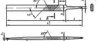
Tooth cut at the base
Tooth trimming
According to the properties of involute gearing, the straight part of the initial generating contour of the gear rack and the involute part of the tooth profile of the cut wheel touch only on the machine gearing line. Beyond this line, the original generating contour intersects the involute profile of the wheel tooth, which leads to the cutting of the tooth at the base, and the cavity between the teeth of the cut wheel becomes wider. Trimming reduces the involute part of the tooth profile (which leads to a reduction in the duration of engagement of each pair of teeth of the designed gear) and weakens the tooth in its dangerous section. Therefore, pruning is unacceptable. To prevent undercutting from occurring, geometric restrictions are imposed on the wheel design, from which the minimum number of teeth is determined at which they will not be undercut. For a standard tool, this number is 17. Undercutting can also be avoided by using a gear manufacturing method other than the running-in method. However, even in this case, the conditions for the minimum number of teeth must be observed, otherwise the depressions between the teeth of the smaller wheel will turn out to be so tight that the teeth of the larger wheel of the manufactured gear will not have enough space for their movement and the gear will jam.
To reduce the overall dimensions of gears, wheels should be designed with a small number of teeth. Therefore, when the number of teeth is less than 17, in order to avoid undercutting, the wheels must be manufactured with a tool offset - increasing the distance between the tool and the workpiece ( corrected
gears).
Sharpening the tooth
As the tool offset increases, the tooth thickness will decrease. This leads to sharpening of the teeth. The risk of sharpening is especially high for wheels with a small number of teeth (less than 17). To prevent chipping of the top of a pointed tooth, the displacement of the tool is limited from above.
Manufacturing of custom gears
Made to order
The production of custom gears is possible according to the customer’s own drawings, indicating the desired shape, module, number of teeth and degree of accuracy. After studying the provided drawing and design documentation, workpieces are prepared and equipment is configured. After the actual manufacturing process of gears, they are tested and certified.
It is possible to manufacture a gear based on a new or used part. And this is not only small, medium or large-scale production of gears, but also the production of single products, for example, for replacing used gears in a mechanism in production.
The cost of the gear production process is calculated individually for each customer and depends on the number and type of parts required, the metal used and the complexity of the work. Modern CNC equipment makes it possible to reproduce a standard model or make a unique product. It has a high accuracy of the production process, due to the elimination of the “human factor”, minimizes defects and costs.