Gear designs
The components of a gear are: a toothed crown that transmits motion, a bearing on which the shaft (of a motor or other part of a mechanism) is connected, and a partition between them.
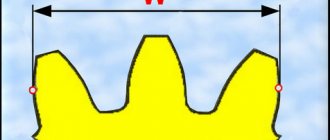
The outer diameter of the gear is equal to the diameter of the pitch circle plus the height of the two tooth heads. Gear sizes can vary greatly. Large objects usually consist of separate sections. The length of a gear is determined by the distance between opposite sides of the same cavity. These are the main parameters of the gear.
In accordance with the purpose, dimensions and technologies for obtaining the workpiece, gear wheels can have different designs:
- Shell gears are used for large diameters and when they must move along a shaft.
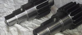
- Spur and bevel gears are integral with the shaft. This is due to the small size of the gears and the fact that separate production reduces accuracy and increases production costs due to an increase in the number of seating surfaces.
Types of gears also include wheels in the form of units, which are formed by assembling individual parts.
Gear types are divided into 3 categories based on the direction of the mounting shafts. Gears that include two axes that are parallel to each other are called parallel-axis gears. Spur, helical and internal gears are commonly used to transmit rotation and power along a parallel axis. Gears in which two axes intersect at one point are called cross-axis gears; common applications include the rotation and power transmission of bevel gears. Linear motion gears are classified as parallel axis gears. Gears with two axes that do not intersect or are parallel are called non-parallel and non-intersecting gears.
Spur gears
Spur gears are the most common type of gear.
The advantages of spur gears are:
- interchangeability (reproducing the inclination angles of an existing mating helical gear of a high-precision mechanism when manufacturing without a drawing (manufacturing a gear according to a sample) presents already known difficulties);
- ease of manufacture (in the repair version, cutting the teeth of a spur gear can be relatively easily done even on universal equipment);
- and therefore relatively low cost.
Methods for making gears
In the replacement gear manufacturing industry, it is very important to select the most efficient and accurate gear processing method and tooling.
Careful preparation for the hardening stage results in a relatively simple operation of turning a hard part followed by hard machining of the gears. When turning hard parts, a good surface finish is important.
Gear machining will change significantly due to e-mobility, new transmission designs and the need to be both flexible and productive. The focus will be on conventional traditional gear machines, and multi-tasking gear machining will become the norm instead.
The traditional method of producing high volume gears, namely gear milling, requires machines and tools specific to the production of gears and in many cases even to the size of the gear itself.
Gear hobbing is a gear manufacturing process in which gear teeth are formed through a series of cuts using a helical cutting tool. The cutter and gear blank rotate without stopping until all the teeth are cut. Gear hobbing is only possible for external gears.
Advantages:
- Reduced overall gear cost compared to high speed steel tools.
- High cutting speed.
- Extended tool life.
- No additional costs.
Cutting
During the manufacturing process, the gear is cut. It is a machining process to create a gear. Gear cutting methods include: broaching, hobbing, milling, forming and grinding.
Broaching is primarily used to make splined or very large gears. The next stage is gear hobbing. For this purpose, special equipment called a milling machine is used. This process produces many types of gears, including spur, spline, worm and helical.
Another gear cutting process is milling, which is not only one of the initial processes but also one of the most important techniques. This uses a router and a router cutter that is run through the gear blank to create the gap between the teeth. One of the main advantages of gear hobbing is that it can produce almost any type of gear.
Finally, there is the finishing and grinding process, where the cut gear is finished by lapping, chipping, polishing, honing or grinding.
Precision cutting produces high-quality gears for agricultural, automotive, manufacturing and other industries.
Rolling
This is a method of creating wheel teeth by plastic deformation, which is carried out using a special tool while rolling it mutually with the workpiece.
We cut teeth
Our company has been manufacturing custom gears and sprockets in St. Petersburg for almost a quarter of a century. We cut teeth not only for cylindrical spur gears, but also for other types of wheels:
- cylindrical helical gears;
- cylindrical gears with an internal crown;
- bevel wheels with straight teeth;
- bevel gears with circular teeth;
- worm wheels and worms;
- gear racks,
as well as sprockets and spline connections according to the Customer’s drawings or samples.
Call us or send your applications with drawings to our email address!
You can find out about our capabilities in the production of gears, sprockets and splines here.
We also provide a wide range of custom metalworking services.
Tooth finishing
Dimensional inaccuracies and the resulting rough surface become a source of large amounts of noise, excessive wear, and backlash between a pair of gears in mesh. All this leads to loss of transmitted power and incorrect speed ratio. Therefore, it is recommended to carry out finishing machining of produced gears. The prepared gear undergoes various hardening processes. So finishing operations must be performed. Commonly used gear finishing operations:
- Polishing gears.
- Gear grinding.
- Gear grinding.
- Gear honing.
The strength of the gear also depends on these operations.
Depending on the material used and the procedure followed, gears can be strong, heat resistant, hard and durable. It is important to note that gears are manufactured in a variety of ways, so there is no single “process” that can be used to describe the creation of all gears.
Programming a method for calculating gearing in Mathcad
The following initial data were taken from the customer’s drawings:
- average normal tooth inclination angle;
- head height coefficient;
- radial clearance coefficient in a pair of original contours;
- nominal diameter of the gear cutting head, etc.
To calculate the meshing geometry of a gear pair, the parameters that directly control the tooth geometry (modulus, number of teeth, crown width) were entered into Pro/ENGINEER as input data and transferred from Pro/ENGINEER to Mathcad as external data. In the Mathcad calculation document this section is called “Input data obtained from Pro/ENGINEER”. This separation of data is normal, since an associative connection is organized between Mathcad and Pro/ENGINEER, thanks to which when the source data changes in Mathcad, the three-dimensional geometry is also updated. Physically, integration with Mathcad is carried out through the “Analysis” constructive element, the parameters of which control the geometry of the model, that is, a change in the source data entails an automatic reconstruction of the three-dimensional model.
The use of Mathcad to automate calculations provides the user with the following set of tools that can reduce time when performing such work and improve the perception of the finished methodology:
- to write formulas, the traditional way of writing formulas and expressions in mathematical literature is used;
- equations are calculated in real time;
- it is possible to accompany the calculation methodology with explanatory drawings and comments;
- a variety of numerical and symbolic operations are supported - calculating values, performing algebraic transformations, including taking into account units of measurement, solving equations, differentiation, integration, etc.
Gears have become widespread as parts of drive technology that are subject to high static and dynamic loads. In this regard, high demands are placed on the accuracy of their manufacture. The manufacturing accuracy of gears depends on the type of unit (mechanism, unit, etc.) in which they are installed and operating conditions. Table 1 shows the parameters of the accuracy and roughness of the lateral surfaces of the teeth of cylindrical gears for various purposes [1].
It should be noted that GOST 1643–81 does not provide for 1st and 2nd degrees of accuracy, although technological processes, equipment and the qualifications of individual manufacturers make it possible to consistently obtain such accuracy. Table 1. Accuracy parameters of spur gears
| Spur gears | Degree of accuracy according to GOST 1643–81 | Surface roughness according to Ra, µm (GOST 2.309–73) |
| Measuring | 3–4 | 0,1–0,8 |
| Gearboxes for gas and steam turbines | 3-5 | 0,3–1,2 |
| Aircraft engines | 3-5 | 0,3–1,2 |
| Metal cutting machines | 3-6 | 0,3–2,0 |
| Railway electric and diesel locomotives | 4–6 | 0,6–2,0 |
| Passenger cars | 5–6 | 0,8–2,0 |
| Passenger buses | 5–7 | 0,8–2,5 |
| Trucks | 5–8 | 0,8–3,2 |
| Motorcycles | 5–7 | 0,8–2,5 |
| Tractors | 6–8 | 1,0–3,2 |
| Marine engines | 4–6 | 0,6–2,0 |
| Wind power plants | 5–6 | 0,6–2,0 |
| General purpose gearboxes | 5–7 | 0,8–2,5 |
In order to achieve the required accuracy and roughness of the side surfaces of the teeth, technological processes and a sequence of gear-processing operations have been developed, which is indicated in Table 2 .
If gears operate under conditions of high bending loads, then to ensure the necessary strength and durability of the gears, high demands are placed not only on the roughness of the side surfaces, but also on the bottom of the tooth cavity. For thermally hardened gears, this is achieved by simultaneously grinding the flanks and the bottom of the tooth cavity. Table 2. Technological processes for processing cylindrical gears
| No. | Sequence of gear processing operations | |||
| 1 | Gear milling, gear shaping, gear cutting (8–9 grade accuracy) | Gear shaving (5–7 degrees of accuracy) | Chemical-thermal treatment (7–9 degrees of accuracy and lower) | Running in, removing nicks and burrs (7–9 grade accuracy, Ra 1.2-3.2 µm) |
| 2 | Gear milling, gear shaping, gear cutting (8–9 grade accuracy) | Gear shaving (5-7 degrees of accuracy) | Chemical-thermal treatment (7–9 degrees of accuracy and lower) | Gear honing (5–8 grade accuracy, Ra 0.2-0.6 µm) |
| 3 | Gear milling, gear shaping, gear cutting (7–8 grade accuracy) | Chemical-thermal treatment (8–9 degrees of accuracy and below) | Chemical-thermal treatment (7–9 degrees of accuracy and lower) | |
| 4 | Gear milling, gear shaping, gear cutting (8–9 grade accuracy) | Chemical-thermal treatment (9–10 accuracy grade and below) | Gear hobbing with carbide hobs (6–8 grade accuracy, Ra 0.2-0.8 µm) | |
| 5 | Gear milling, gear shaping, gear cutting (8–9 grade accuracy) | Chemical-thermal treatment (9–10 accuracy grade and below) | Gear grinding (3–6 grade accuracy, Ra 0.3-1.6 µm) | |
The production of high-quality gears requires the production of blanks with precise dimensions and shapes of the base surfaces used in machining, inspection and assembly. Inaccuracy in the manufacture of workpieces is one of the reasons for the formation of gearing errors. For cylindrical wheel blanks, as a rule, the central hole d and the end close to the ring gear are used as base surfaces ( Fig. 1 ). For cylindrical gears of 3–4 degrees of accuracy (GOST 1643–81), the base holes and shaft journals are made with accuracy Н5‑Н6 and h5‑h6 (GOST 25347–82), and for wheels of 5–6 degrees of accuracy - with accuracy Н6‑ Н7 and h6‑h7.
Rice. 1. Disc type spur gear blank
Very often, tolerances also stipulate deviations from the roundness and conicality of the base holes and shaft journals. As a rule, these deviations are set within half the size tolerance. In addition, the blanks of cylindrical gears of the disk type must be maintained with high precision in the runout of the base end and the parallelism of the base ends, which is especially important when processing teeth on several workpieces simultaneously. In automated production during gear grinding, to ensure accurate alignment of the teeth relative to the grinding wheel, the runout of the outer diameter da should be no more than 0.13 mm. In most cases, finishing of the base surfaces of gear blanks is carried out by grinding. Good results are obtained when processing on a universal CNC cylindrical grinding machine from STUDER mod. S31, which is designed for external, internal and end grinding in single, small, medium and large series production. The machine is produced in two versions with a distance between centers of up to 650 mm and up to 1000 mm, a center height of 175 mm, a grinding wheel with a diameter of 500 mm and a height of up to 63 mm ( Fig. 2 ).
Rice. 2. Universal cylindrical grinding machine from STUDER mod. S31 For grinding internal holes, a high-speed spindle with a speed of 24,000–120,000 per minute is installed on the machine. The main feature of the machine should be considered a frame made of Granitan S103 polymer concrete, which contributes to the active damping of both internal and external vibrations, improving damping and temperature-dependent (from heating the working area of the machine) characteristics [2]. Comparative studies of the dynamic characteristics of lathes of JSC "Krasny Proletary" mod. MK 6510 F4 and cylindrical grinder from STUDER mod. S31 made it possible to identify significant advantages of frames made of polymer concrete and metal concrete compared to a frame made of cast iron: in terms of vibration damping time, on average, 3 times and 4 times in terms of the characteristics of the logarithmic decrement of vibration damping ( Table 3 ).
Table 3. Vibration damping indicator for various machines
| Machine name | Bed material | Damping time of oscillations upon impact, ms | Characteristics of the logarithmic decrement of vibration damping |
| Lathe mod. MK6510 F4 | Cast iron | 69 | 35 |
| Lathe mod. MK6510 F4 | Metal concrete | 27 | 112 |
| Cylindrical grinding machine mod. S31 | Polymer concrete Granitan S103 | 22 | 133 |
To consistently ensure the accuracy of teeth of grade 5–6 according to GOST 1758–81 after chemical-thermal treatment of driving hypoid gears (number of teeth z = 11, external circumferential module mte = 7.37 mm, external tooth height he = 16 mm, average angle tooth inclination β = 45° 23′) grinding of base journals with a diameter of 65 and 45 mm, as well as the base end T was carried out on a cylindrical grinding machine mod. S31 ( Fig. 3 ). The processing was carried out based on the teeth and the center hole of the shank. Along with accurate diametrical dimensions, consistently high values of radial runout of the journals of 5–8 μm and end runout of 6–10 μm were obtained.
Rice. 3. Hypoid drive gear The principle of rolling gear turning is based on the engagement of a screw gear, which is formed by the gear blank 1 and the cutter 2, the axes of which are installed at a crossing angle. The crossing angle depends on the angle of inclination of the teeth of the wheel β2 and the cutter β0. During the cutting process, with the mutual circular movement of the tool and the workpiece at a speed V, as well as under the action of the axial movement of the feed Sо, the entire width of the gear rim is processed. By crossing the axes, a relative speed arises between the tool and the workpiece. High cutting speed is determined by the angle of crossing of the axes and the number of revolutions of the tool. Since the contact between the tool and the workpiece during gear cutting is short-term, the cutting process occurs with low heat generation. The principle of operation of rolling gear turning has been known for more than 100 years, but the highly dynamic kinematics of the process creates serious problems for the tool, which reduces its durability and the accuracy of tooth production. Therefore, the process of rolling gear turning has not been used in serial and mass production for a long time.
Rice. 4. Scheme of rolling gear turning
Rice. 5. Machine for rolling gear turning mod. LK 500 In 2016, the company KLINGELNBERG (Germany) began to produce rolling gear cutting on a gear cutting machine mod. OERLIKON WITH 29 cutting heads with sharpened carbide cutters [3]. Taking into account the fact that gear turning has great prospects for processing internal ring gears of planetary gears of buses, cars and trucks, construction, aviation and other equipment, LIBHERR (Germany) has improved the gear turning technology. Processing of workpieces with a maximum diameter of 300/500 mm is carried out on machines mod. LK 300/500 with a maximum spindle power of 32 kW ( Fig. 5 ). For gear machining, LIBHERR has developed a special tool that can withstand high loads: 1. Tools made of powdered high-speed steel with a wear-resistant coating have a price advantage and low durability. 2. A carbide tool with a wear-resistant coating has high durability, but due to the cost of the material and the labor intensity of manufacturing, it is approximately three times more expensive than a high-speed tool. Used in large-scale and mass production. 3. Tools with carbide inserts are usually used for rough machining; subsequent finishing machining is carried out with high-speed tools made from powder steels. The machine can perform processing with coolant supply or with pressurized air cooling. The improved gear turning process can successfully compete with gear shaping and grooving ( Table 2 ). Compared to gear shaping, gear shaping provides the same accuracy of gears, sometimes even higher, and is three times more productive. Gear turning requires significantly less infeed and overtravel distance compared to gear hobbing, so it can be used for parts with limited access to the ring gear. Rolling gear hobbing of cylindrical wheels is characterized by significant labor intensity with a large volume of metal being removed and difficult cutting conditions, when the formation of chips by the main and auxiliary cutting edges of the teeth of the hob is difficult. Therefore, technical solutions aimed at increasing the productivity of rolling gear hobbing, the reliability of the process and its economic efficiency are relevant for industrial production ( Fig. 6 ).
Rice. 6. Scheme of rolling gear hobbing Currently, gear hobbing with the supply of cutting fluid (coolant) is widely used. Expensive mineral and synthetic oils are used as coolants. The fumes generated when using oils pollute the environment as they contain chlorine, heavy metals and aromatic hydrocarbons. Coolant supply reduces friction wear, cools the cutting tool and workpiece, and removes chips from the machining zone. However, uneven cooling and varying cutting conditions cause increased wear on the engaging cutting edge of the cutter teeth. The durability of hob cutters decreases and tool consumption increases. In addition, in recent years, the cost of coolant disposal has increased significantly, which in the workshop cost can be 15–20%. Under these conditions, some manufacturers of cylindrical gears are turning their attention to gear hobbing without coolant. When hobbing with coolant, as a rule, a single-cycle method of axial movement of the cutter is used. After processing one or several workpieces, the hob cutter is automatically moved along the axis and the unworn or partially worn part of the cutter is put into operation. The disadvantage of the single-cycle method is the high thermal load on the cutter teeth. In order to reduce the heat stress of the process during thermally intensive gear hobbing of cylindrical wheels (mn = 2.75 mm, z = 27, α = 20°, β = 18°, b = 16 mm, d = 74.25 mm) without coolant supply, a multi-cycle method of axial movement of the cutter. After processing one workpiece, the axial movement of the cutter was carried out along arrow 4 by a value of h = 9.2 mm, significantly greater than with the single-cycle method ( Fig. 7 ). The cutter teeth had minor wear and could be used for a few more cycles. The movement 4 was carried out against the direction of rotation of the workpiece 3. In this case, the cutter teeth 5 that were not involved in the work finally formed the profile of the wheel teeth. After the cutting zone reaches the end of the working length of the cutter 6, the first cycle n ends. The cutter teeth had minor wear and could be used for a few more cycles. After which the cutter returned to position 1, starting the second cycle - 2n with a displacement ∆h from the initial position 2.
Rice. 7. Scheme of multi-cycle axial movement of a hob cutter Research has shown that during gear hobbing without coolant supply and a multi-cycle method of axial movement, the life of the hob cutter between regrinds with permissible wear hz ≤ 0.5 mm on the back surface of the teeth increased by 1.5–1.7 times compared to single-cycle method 2 ( Fig. 8 ) After milling without coolant, the accuracy of the teeth in terms of fluctuations in the measuring center distance per wheel revolution was Fi” = 0.04÷0.063 mm and on one tooth – fi” = 0.02÷0.036 mm.
Rice.
8. Durability of the hob cutter during single-cycle and multi-cycle axial movement Table 4. Cutting speed during gear hobbing without coolant supply
| Tensile strength N/mm2 | 600 | 700 | 800 | 900 | 1000 | 1100 |
| Brinell hardness | 174 | 203 | 232 | 261 | 290 | 320 |
| Cutting speed m/min | 160 | 140 | 120 | 100 | 85 | 70 |
As a result of the studies, optimal cutting speeds were established for gear hobbing with hobs made of powdered high-speed steel with wear-resistant coatings without coolant supply, depending on the tensile strength and Brinell hardness of workpieces made of alloy steels being processed ( Table 4 ). The technology for high-speed hobbing of cylindrical wheels without coolant provides new opportunities aimed at reducing machine time and processing costs, increasing manufacturing accuracy and environmental conditions of production. Gear hobbing machines must have a higher rotation speed of the cutter and table, reliable and quick removal of hot chips from the working area of the machine, so that thermal energy does not affect the machine components. All these requirements are met by gear hobbing machines from LIBHERR mod. LC 200, LC 300, LC 380 and LC500 ( Fig. 9 ). It should also be noted a gear hobbing machine with a horizontal working spindle from KOEPFER (Germany) mod. 160, which processes the teeth of fine-grained planetary gears without coolant in a record time of 8–10 seconds.
Rice. 9. Gear hobbing machine from LIBHERR mod. LC 500 (max module = 7 mm, Dmax = 500 mm)
Rice. 10. Gear hobbing machine from KOEPFER mod. 160 (max module = 2.5 mm, Dmax = 140 mm)
To obtain the required strength properties, cylindrical and bevel gears made of alloy steels are preferably gas carburized (nitrocarburized) in controlled endothermic atmospheres, followed by oil quenching. In this case, the CHT process is carried out in automated through-pass and chamber units, which have high productivity and provide a full processing cycle from heating to hardening of gears [1]. However, along with the necessary hardening, gears undergo significant volumetric deformation during chemical treatment, and the accuracy of the teeth decreases by 1–2 degrees or more ( Table 2 ). The base and other surfaces of the gear blanks are also deformed. It is known that the deformation of gears during chemical treatment is influenced by a large number of factors, including: the design of the workpiece, the properties of the steel used, methods for producing forgings, preliminary heat treatment, conditions for machining, etc. However, as some authors note, the decisive influence on Deformation of gears is caused by unequal cooling intensity of different surfaces of workpieces during hardening [4, 5].
Rice. 11. Scheme of quenching the workpiece in oil In Fig. Figure 11 shows a diagram of hardening a cylindrical workpiece; oil is used as a cooling medium. When a heated workpiece is dipped into oil, it is in three different zones: convection (a type of heat transfer), nucleate and film boiling. This causes large temperature differences both inside and on the surface of the workpiece. For example, within 10 s after dipping a heated cylindrical workpiece into oil, the surface temperature of its lower part was 200°C and increased when going deeper into the workpiece to 700°C, and the temperature of the upper part of the workpiece was 700...750°C. The different cooling intensity of individual parts and surfaces of the workpiece during oil quenching causes significant deformations. In order to reduce the deformation of the teeth and base surfaces of the drive bevel gear made of 25KhGT steel ( Fig. 3 ), it was decided to carry out chemical treatment using a combination of vacuum carburization and gas hardening under pressure. The decisive advantage of gas pressure quenching compared to oil cooling is the reduction of gear errors that occur during phase transitions. Heat transfer is carried out homogeneously, so there are prerequisites for minimizing changes in the size and shape of the teeth, as well as the base surfaces of the gears due to deformation. When quenching with an inert gas (nitrogen or helium) with high pressure (up to 2 MPa) and gas flow rate (up to 25 m/s), the surface temperature of the cylindrical workpiece is the same along the entire length (250°C), it gradually increases as it deepens into the workpiece up to 750°C ( Fig. 12 ). It is very important that the cooling of the workpiece along its entire length occurs evenly with the same intensity. This allows for a significant reduction in deformation compared to oil quenching.
Rice. 12. Scheme of quenching a workpiece with gas under pressure
Studies have shown that when cooled with gas (helium) under a pressure of 16 bar, a surface hardness of 60–62 HRC was obtained with an effective thickness of the cementation layer heff = 1.6–1.85 mm. The values of the radial runout of the journals Ø 65 mm and Ø 45 mm of the hypoid gear and their spread were significantly reduced to 0.02–0.10 mm instead of 0.2–0.15 mm when quenched in oil, which made it possible to avoid the operations of cleaning the centers and straightening the journals gears. Measurements of the norm of kinematic accuracy of the radial runout of the ring gear Fr, the largest difference in distances from the working axis of the gear to the element of the normal initial contour showed that the accuracy of the ring gear after gas vacuum carburizing and hardening with gas under pressure 1 is approximately one degree higher according to GOST 1758–81 compared to carburization in endothermic atmospheres and quenching in oil 2 ( Fig. 13 ). At the same time, the indicator of the standard of smooth operation - pitch deviation fpt = ± (15–33) µm was also within the 8th degree of accuracy according to GOST 1758–81.
Rice. 13. Measuring the runout of the ring gear of the hypoid gear
Conclusion
In order to increase the accuracy, productivity and economic efficiency of gear manufacturing, new technologies, equipment, cutting tools and technological equipment are being developed: 1. Machining machines with high statistical and dynamic rigidity (frames made of polymer concrete and other materials), as well as micrometric positioning and movement accuracy controlled axes. 2. Technological methods and cutting tools that allow processing without the supply of cutting fluid. 3. New innovative methods of chemical-thermal treatment, including gas carburization (nitrocarburization) in combination with direct hardening with high pressure gas.
Literature 1. Kalashnikov A. S., Morgunov Yu. A., Kalashnikov P. A. Modern methods of processing gears. Tutorial. Publishing house "Spectrum", 2012. 238 p. 2. Vetrov S.I., Brailovsky M.I., Skripkin A.M., Golovastov V.A. Metal-concrete composite base parts of high-precision lathes. ITO No. 2. 2008. pp. 52–60. 3. Kalashnikov A. S. Trends in the development of gear processing. "RHYTHM Mechanical Engineering". 2016. No. 3. pp. 12–19. 4. Zinchenko V. M. Engineering of the surface of gears using chemical-thermal treatment methods. M.: Publishing house of MSTU im. N. E. Bauman, 2001. 302 p. 5. Loser K. Innovative Warmebehandlung sprozesse und-anlage in der Getribeproduktion. Report at the GETRO Congress, Germany, Wurzburg. March 2007. 15 p.

