Mechanical advantage: torque vs. rotation speed
Gear drives operate on the principle of mechanical advantage. This means that by using gears of different diameters you can vary the speed of rotation of the output shaft and the torque produced by the drive motor.
Any electric motor has a certain rotation speed and torque corresponding to its power. But, unfortunately, for many mechanisms, asynchronous motors offered on the market and suitable for the cost usually do not have the desired relationship between speed and torque (the exception is servos and high-torque gearmotors). For example, do you really want your robot cleaner's wheels to spin at 3000 rpm with low torque? Of course not, which is why the latter is often preferable to speed.
Gear Equation
It trades high input speed for greater output torque. This exchange occurs according to a very simple equation, which can be written as follows:
Input torque * Input speed = Output torque * Output speed
The input speed can be found by simply looking at the drive motor nameplate. The input torque can be easily determined by this speed and mechanical power from the same plate. Then we simply plug the output speed or required torque into the right side of the equation.
For example, let's say that your induction motor has a speed of 50 rps with an output torque of 0.5 N∙m, but you only want 5 rps. Then your equation will look like this:
0.5 N∙m * 50 r/s = Output torque* 5 r/s.
Your torque output will be 5 Nm.
Now let's say that with the same motor you need 5 Nm, but a minimum speed of 10 rps is required. How would you know if your motor and gear train (that is, essentially a geared motor) is capable of this? Let's look again at our equation
0.5 N∙m * 50 r/s = 5 N∙m * Output speed,
Output speed = 5 rps.
So, you have determined, using a simple equation, that with the indicator Output torque = 5 N∙m, your gear transmission is not capable of providing an output speed of 10 rps. You just saved yourself a ton of money because you didn't spend it on a machine that would never work.
Gear ratio
We've written down the equations, but how do we mechanically reverse torque and speed? This requires two gears (sometimes more) of different diameters to have a specific gear ratio. In any pair of gears, the larger gear will move more slowly than the smaller one, but it will transmit more torque to the output shaft. Thus, the greater the difference (or gear ratio) between two wheels, the greater the difference in their speeds and transmitted torques.
The gear ratio shows how many times the gear train changes speed and torque. Again, there is a very simple equation for this.
Let's assume the gear ratio is 3/1. This will mean that you triple your torque and triple your speed.
Input torque = 1.5 N∙m, Input speed = 100 r/s,
Gear ratio = 2/3
Output torque = Input torque * 2/3 = 1 N∙m,
Output speed = Input speed * 3/2 = 150 rps.
So, at the transmission output, the torque increased by one and a half times, and the speed decreased in the same way.
Design of gears and worm wheels
2.4.6.1 Design of spur gears
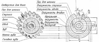
The design of gear wheels is shown in Fig. 2.2. Gears consist of a rim, a disc and a hub.
| A | b |
| Rice. 2.2. Gear design |
The diameter of the circle of the projections and the width of the gear rim are determined during the design calculation.
Rim thickness S
for all types of wheels you can accept:
.
At the ends of the ring gear (teeth and rim corners), chamfers are made (Fig. 2.3):
,
which are rounded to a standard value according to the same series as (see Table 2.3).
On all spur gears, the chamfer is made at an angle of 45° (Fig. 2.3 a
).
On helical and chevron wheels with a hardness of less than 350 HB, the chamfer is made at an angle of 45° (Fig. 2.3 a
), with higher hardness - at an angle of 15...20° (Fig. 2.3
b
).
| A | b |
| Rice. 2.3. Chamfer design at the ends of the ring gear |
Hub outer diameter (see Fig. 2.2):
– for a steel hub with a keyed connection and an interference fit;
– for a steel hub with a spline connection;
– for a cast iron hub.
Hub length:
– smaller values for an interference fit on the shaft, larger values for a transitional fit;
– optimal value;
It is finally accepted after calculating the shaft-hub connection.
Gear wheels for gearboxes most often have a symmetrically located hub.
Sharp edges at the ends of the hub are blunted with chamfers, the dimensions of which are taken according to table 2.5.
Table 2.5
Recommended chamfer value
| 20…30 | 30…40 | 40…50 | 50…80 | 80…120 | 120…150 | 150…250 | 250…500 |
| 1,0 | 1,2 | 1,6 | 2,0 | 2,5 | 3,0 | 4,0 | 5,0 |
The same chamfer size can be used to blunt the inner edge of the rim.
Gear wheels of small diameter (up to 150 mm) have a simple shape. The workpiece is obtained from rolled stock (Fig. 2.4 a
and rice
2.5 a
) or free forging (Fig. 2.4
b
and Fig. 2.5
b
). They are used in both serial and single production.
| A | b |
| Rice. 2.4. Small diameter gear design |
This design can be used if the thickness of the rim in the place weakened by the keyway is at least 2.5 m
, otherwise the gear wheel must be made integral with the shaft (see paragraph 2.4.6.2, “Design of gear shaft”).
To reduce the amount of precision cutting, grooves are made on the wheel rims (for wheels > 80 mm) (Fig. 2.5). The same wheel design can be used for wheels of larger diameter (up to 500 mm) in single production, if there are no strict weight requirements.
| A | b |
| Rice. 2.5. Small diameter gear design |
Forged wheels (Fig. 2.6) - wheels of larger diameter (up to 500 mm) in single and small-scale production are produced from rolled stock by free forging followed by turning.
| Rice. 2.6. Design of forged gears |
Disc thickness. To reduce weight, in technically justified cases, you can take 4...6 large-diameter holes in the disk.
Curvature radii.
Stamped wheels - in mass production, wheel blanks with a diameter of up to 500 mm are obtained from round steel by forging in dies. With an annual production volume of up to 100 pcs. Forging in the simplest one-sided backing dies is economically justified (Fig. 2.7). For free removal of workpieces from the stamp, the values of stamping slopes and radii of curvature R
³ 6 mm.
| Rice. 2.7. Design of stamped gears |
Disc thickness.
With an annual production volume of more than 100 pcs. double-sided stamps are used (Fig. 2.8).
| Rice. 2.8. Design of stamped gears |
To reduce the influence of volumetric heat treatment on the accuracy of the geometric shape, gears can be made massive (Fig. 2.9): .
| Rice. 2.9. Design of stamped gears |
Solid wheels - used in mass production, as the least labor-intensive, for the manufacture of wheels with a diameter of over 500 mm. In terms of their load-bearing capacity, they are inferior to wheels with a forged or rolled rim. Up to a diameter of 900 mm, they are mainly made with single disks (Fig. 2.10 a
), and with large diameters and widths, it is reinforced with ribs (Fig. 2.10
b
) or made with double disks (Fig. 2.10
c
).
| A | b | V |
| Rice. 2.10. Cast Gear Design |
The spokes can have a cross-shaped, T-shaped, I-beam, oval or other cross-sectional shape. The cross-sectional dimensions of the spokes at the hub are determined from their conditional calculation for bending. Since the rim stiffness is low, the load distribution between the spokes is very uneven. If the circumferential force on the wheel is , then it is conventionally assumed that the load on the most loaded spoke is:
,
where T
– torque on the wheel;
d
– pitch diameter of the wheel;
– number of spokes.
Then the condition for the strength of the spokes is:
where is the axial moment of resistance of the spoke section.
For free removal of blanks from the mold, take the values of casting slopes and radii of curvature R
³ 10 mm.
To avoid runout and vibration during operation, gears are balanced by drilling holes at the end of the rim if their rotation speed exceeds 1000 rpm.
2.4.6.2 Gear shaft design
Gear shafts are used in cases where the diameter of the shaft is close in size to the diameter of the gear (mainly in gearboxes at 3.15),
| Rice. 2.11. Design of cylindrical gear shafts |
The design of the gear shaft must ensure cutting teeth with free exit of the tool (Fig. 2.11 a
).
For large gear ratios, it is possible to manufacture a gear shaft with teeth cutting into the shaft body (Fig. 2.11 b
,
c
). The output of the cutter is determined graphically by its outer diameter. It is advisable to avoid the use of mortise gear shafts, since in this case milling and grinding of teeth is difficult. In this case, the diameter of the circle of the gear cavities should not be less than the calculated diameter of the shaft.
If possible, the tool entry should be provided from the side of the shaft shoulder (Fig. 2.11 d
).
2.4.6.3 Worm design
The worms work together with the shaft. Mounted worms are used extremely rarely. The main dimensions of the worm (diameters , , , length) are determined during design. Approximate distance between supports l
determined at the stage of preliminary design of the gearbox.
One of the main requirements for the design of a worm shaft is to ensure high rigidity. For this purpose, they try to keep the distance between the supports as small as possible.
| A |
| b |
| V |
| Rice. 2.12. Design of cylindrical worms |
The diameter of the worm shaft in the unthreaded part is chosen to ensure, if possible, free exit of the tool when processing turns and the required size of the thrust shoulder for the bearing (Fig. 2.12 a
).
If the diameter of the worm is not large enough to provide the required shoulder height, then it is necessary to provide a shoulder (Fig. 2.12 b
).
With a small diameter, the worm must be made according to Fig. 2.12v _
.
In this case, the shoulders are made as shown in Fig. 2.12a ,
and according to Fig.
2.12 b
.
2.4.6.4 Worm wheel design
The main dimensions of the worm wheel rim (diameters , , , , rim width) are determined during the design.
The radius of the recessed surface of the tops of the wheel teeth (Fig. 2.13) is determined by the diameter of the worm:
,
where is the pitch diameter of the worm.
m
– transmission module.
| Rice. 2.13. Worm wheel ring dimensions |
At the ends of the worm wheel, chamfers are made, rounded to a standard value (the standard size range of chamfers is given in Table 2.6).
Worm wheels of small diameter (up to 100-120 mm) are made in one piece
. The thickness of the rim in this case can be taken:
.
The dimensions of the disk and hub are the same as for prefabricated wheels.
Larger wheels are made prefabricated to save expensive bronze. Wheel disc
are made of cheaper cast iron or steel,
the gear ring
is made of bronze.
The cutting of the worm wheel teeth is carried out after assembly.
The design of the disk depends on the output volume. In small-scale production, disc blanks are obtained from rolled products or forgings, followed by turning (Fig. 2.14 a
).
In mass production (annual production volume over 100 pcs.), it is preferable to manufacture stamped or cast disks (Fig. 2.14 b
).
To facilitate the removal of the workpiece from a stamp or mold, it is necessary to provide slopes and radii of curvature mm on the rim and hub. For forged and turned disks, the radii of curvature are mm.
| A | b |
| Rice. 2.14. Assembly disk worm wheel design |
Worm ring thickness S
: .
Rim thickness: .
Hence the outer diameter of the disk: .
Rim inner diameter: .
Disk thickness, but not less.
Hub outer diameter:
– for a steel hub with a keyed connection and an interference fit;
– for a steel hub with a spline connection;
– for a cast iron hub.
Hub length:
– smaller values for an interference fit on the shaft, larger values for a transitional fit;
– optimal value;
It is finally accepted after calculating the shaft-hub connection.
Geared worm wheels most often have a symmetrically located hub.
Worm wheels weighing more than 20 kg must have 4...6 holes on the disk for slinging. The diameter of the holes is taken structurally.
Sharp edges at the ends of the hub are blunted with chamfers, the dimensions of which are taken according to table 2.6.
Table 2.6
Recommended chamfer dimensions f
| 20…30 | 30…40 | 40…50 | 50…80 | 80…120 | 120…150 | 150…250 | 250…500 |
| 1,0 | 1,2 | 1,6 | 2,0 | 2,5 | 3,0 | 4,0 | 5,0 |
The same chamfer size can be used to blunt the inner edge of the rim.
The connection between the crown and the disk must ensure the transmission of high torque and relatively small axial force. The design of the crown and the method of connection to the disk depends on the output volume.
For single and small-scale production
and
small wheel sizes
(300 mm), the rims are pressed onto the disk
( Fig. 2.15).
Rim thickness: .
With a constant direction of rotation of the worm wheel, a shoulder is provided on the outer surface of the disk (Fig. 2.15 a
), which absorbs the axial force. The dimensions of the collar can be taken as follows: ; . The reverse gear wheel can be made without a shoulder.
| A | b |
| Rice. 2.15. Fastening the worm ring with interference |
With relatively small interference (or acceptance of interference without calculation), to guarantee non-rotation, screws are installed at the junction of the worm ring and the disk (Fig. 2.15 b
) as a cylindrical key (usually 3...4 pieces around the circumference).
For large wheel sizes
(300 mm) the crown can be attached to the disk using tight-fitting bolts (for reaming) (Fig. 2.16) or rivets.
In this case, the crown is pre-centered along the diameter D
, and the mating is performed using a transitional fit.
Rim thickness: .
| Rice. 2.16. Fastening the worm ring with bolts |
In this design, it is necessary to ensure reliable locking of the nut from self-unscrewing; for this, it is not recommended to use spring washers
.
In mass production
It is more economically profitable to produce wheels with rims obtained by casting. A cast iron or steel disk heated to 700…800ºС is placed in a metal mold, heated to 150…200ºС and filled with molten bronze. When cooling, a tension arises between the disk and the crown, caused by the shrinkage of the solidifying liquid metal of the crown.
The thickness of the crown during casting is assumed to be .
Discs are made by turning, stamping or die casting. The outer surfaces of cast disks are not mechanically processed. They are degreased and cleaned of oxide films using chemical treatment. 6...8 recesses are provided on the rim of the disk; after casting, protrusions are formed on the rim that absorb both circumferential and axial forces.
The concave outer surface of the disk (Fig. 2.17 a
,
b
) are obtained by turning.
Transverse grooves are obtained by radial feed of the cutter: disk (Fig. 2.17 a
) - perpendicular to the axis of rotation of the wheel or cylindrical (Fig. 2.17
b
) - parallel to the axis of rotation. Slot dimensions: ; .
The recesses on the disk rim can be drilled (Fig. 2.17 in
).
In Fig. 2.17 g
,
d
shows discs with grooves obtained by casting a disc into a mold.
| Rice. 2.17. Design of worm rings produced by casting |
2.4.6.5 Selection of fits, maximum deviations, tolerances of shapes and location of surfaces, roughness.
Tolerances and maximum deviations of the dimensions of wheels and worms
Tolerances on the size of the diameter of the circle of the protrusions can be accepted: for gear wheels of the 7th degree of accuracy - h8
, 8 degrees of accuracy –
h9
, 9 degrees of accuracy –
h10
.
For the 11th degree of accuracy (straight and narrow helical gear wheels in manual drives) in reverse gears - h11
, in non-reversible gears -
h12
.
Tolerance for hub length is h11-h12
.
Tolerances for other sizes are usually taken according to quality 14.
Roughness of wheel and worm surfaces
The surfaces of gear and worm gear elements must have the roughness indicated in Table 2.7.
Table 2.7
Roughness of the surfaces of gear and worm wheel elements
| Gear elements | Roughness, Ra, µm |
| Working surfaces of gear teeth | 0,8 – 0,1 |
| Working surfaces of worm wheel teeth | 0,8 – 0,4 |
| Working surfaces of worm turns | 0,4 – 0,2 |
| Tooth lug surfaces | 6,3 |
| Chamfers and grooves on gears and worm wheels | 6,3 |
| The ends of the hubs, based on the end of the shaft shoulders, at the ratio | 1,6 |
| Same with attitude | 3,2 |
| Working surfaces of keyways | 1,6 |
| Non-working surfaces of keyways | 3,2 |
| Mounting surfaces of holes when landing H7 : | |
| for diameters ≤ 50 mm | 0,8 |
| for diameters > 50 mm | 1,6 |
Reaching a certain gear ratio
If you want to achieve a simple ratio, say 2 to 1, you would use two gears, one twice the size of the other. This is nothing more than the ratio of their diameters. If the diameter of the gear is 3 times larger than the other gear it engages, then you will get a gear ratio of 3/1 (or 1/3).
For a much more accurate way to calculate the gear ratio, count the ratio of the teeth on the gears. If one has 28 teeth and the other has 13, you will get a gear ratio of 28 / 13 = 2.15 or 13 / 28 = 0.46. Counting the teeth will always give you the most accurate value.
Gear efficiency
Unfortunately, in a gear train you have certain energy losses. This is due to obvious reasons such as friction, pressure angle mismatch, lubrication, clearances (the distance between the meshed teeth of two gears), and angular momentum, etc. Different types of gears, different types of gears, different materials and wear of gears, - all this will affect the transmission efficiency. Their possible combinations will give too large a list, so you can find the exact value of the efficiency of the gear you are using in the documentation for it.
Let's assume you are using two spur gears. The typical efficiency of such a transmission is approximately
90%. Multiply this number by your output speed and output torque to get the true transmission output values.
If (from the previous example):
Gear ratio = 2/3
Output torque = Input torque * 2/3 = 1 N∙m,
Output speed = Input speed * 3/2 = 150 rps,
True output torque = 1 N∙m * 0.9= 0.9 N∙m,
True Output Speed = 150 rps * 0.9 = 135 rps.
Toothed cylindrical wheels
The shape of gears in most cases is determined depending on the method of obtaining the workpiece. In turn, the method for obtaining the workpiece is chosen taking into account the material and size of the wheels, as well as the production volume. In single and small-scale production, gears with a diameter of da ≈ 200 mm are made from round bars, forgings and welded. At da ≈ 150 ÷ 600 mm, the workpiece is produced by forging in the form of round forgings. In large-scale and mass production, wheel blanks of small and medium diameters (da up to 600 mm) are produced by stamping in double-sided dies, and larger sizes by casting or welding.
Wheels of large diameters are usually made cast, wheels of relatively low-speed and lightly loaded gears are made cast and with smaller diameters. In individual production, wheels of large diameters are also welded.
In the design of gears, there are (Fig. 3) a ring gear or rim, a hub and a disk that connects the ring gear to the hub. Gear wheels are designed in two types: the ring gear is made directly on the shaft (gear shaft) and the ring gear is made together with the disk and hub for connection to the shaft during assembly (mounted gear).
Rice. 3. Gear elements
The ring gear of a gear is usually 3...10 mm wider than the ring gear of a wheel. At the ends of the ring gear, chamfers of size f=(0.6...0.7)m are made. On spur wheels, chamfers are made at an angle αφ=45°, on helical wheels with a hardness of the working surfaces HB<350, chamfers are made at an angle αφ=45°, and with HB>350, chamfers are made at an angle αφ=15°.
With diameters d>500 mm, heavily loaded wheels can be made with tires. The bandage (rim) is made of alloy steel or bronze, the center is made of cheap carbon steel, cast or welded, as well as cast iron (Fig. 3, c).
Bandage thickness (mm) along the tooth cavities: at z<150
at z>150
Hub. The outer diameter of the hub (Fig. 4) for steel wheels is dst = (1.55...1.7)d mm and for cast iron wheels - dst = (1.7...1.8)d mm; thickness – δst ≈ (0.3…0.4)d mm; length – lst=(1.0…1.2)d mm.
To ensure normal operation, gears and worm wheels must be installed on the shafts without distortion. If the wheel hub has a sufficiently long length lst ≥0.8d mm (in gearboxes this ratio is accepted lst = (1...1.5)d mm), then the gear or worm wheel will sit on the shaft without distortions.
Rice. 4. Gear design: a – with a straight disk; b – with an inclined disk
In the drives of production machines and in gearboxes, gear wheels of relatively small diameters are used, mounted on shafts. They are made from round or sheet metal, from forgings or welded. Depending on the design requirements, the ring gear of the mounted wheel can be located symmetrically relative to the hub or asymmetrically. As a result, this determines the position and shape of the disk, which must ensure the resistance of the gear to the perceived loads.
To ensure a strong connection between gear hubs and shafts during keyed connections, it is recommended to use the following fits (in parentheses for reverse gears):
- for spur gears H7/p6 (H7/r6);
- for cylindrical helical and worm wheels H7/r6 (H7/s7);
- for bevel wheels H7/s7 (H7/t6).
To ensure the ability to move the wheel on the shaft during the transmission of rotation, fits H7/g6 (H7/f7) are used.
Disk. Wheels with a tooth tip diameter of da≤250 mm are made in the form of disks, with or without spokes. These steel wheels have recesses of 2...5 mm to highlight
machined end, which serves as a technological base for cutting and mounting wheels. Cast gears d ≤500 ÷ 600 mm are made (Fig. 4) with a straight (a) and inclined (b) disk.
Rice. 5. Cast gears d ≥500 ÷ 1000 mm: solid (a); with bandage (b)
Cast iron wheels, used in low-speed, lightly loaded gears, most often open, are made cast. For cast wheels, 4...6 holes are made in the disks (Fig. 5). The holes are used for fastening the wheel when processing the workpiece and allow processing the hole for the shaft and the outer surface of the rim in one installation, and are also used when transporting wheels. With large hole sizes, they serve to reduce the weight of the wheels; in cast wheels, they serve to allow the casting gases to escape during casting.
The shape of the spokes for cast wheels is shown in Fig. 6. Elliptical cross-section spokes are used for light loads, cruciform and tee cross-sections are used for medium loads, and I-section spokes are used for transmission operation under severe conditions.
Rice. 6. Cross-sectional shapes of the spokes of cast gears: a – elliptical; b – tee; c – cruciform; g, e – I-beam
The design of forged cylindrical gears is shown in Fig. 7.
Rice. 7. Design of forged cylindrical gears: a – dа≤200 mm; b – da≤500 mm
Gear rotation direction
When designing any gear train, you need to understand how it changes the direction of rotation of the output shaft. Two meshed gears will always rotate in opposite directions. This means that if one rotates clockwise, the other will always rotate counterclockwise. This is quite obvious. But what if you have a transmission of, say, six meshed gears? The rule here is as follows: the input and output shafts of gears with an odd number of gears always rotate in one direction, and with an even number of gears, in the opposite direction.
Gear design and parameters
It contains a ring with teeth, a disk and a hub. There are three most important parameters: module, pitch circle diameter and number of teeth. What pitch circle does a gear wheel have? A drawing of a spur wheel with typical involute teeth is shown below.
Read also: How much gold is in microcircuits
For example, a gear with 22 teeth and a diameter of 44 mm has a module m = 2 mm. The meshed gears must both have the same module. Their values are standardized, and it is on the pitch circle that the module of a given wheel takes on its standard value.
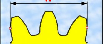
The height of the tooth head of one wheel is less than the height of the tooth foot of the second one, which engages with it, due to which a radial clearance c is formed.
To ensure the lateral clearance δ between two meshed teeth, the sum of their thicknesses is taken to be less than their circumferential pitch p. Radial and lateral clearances are provided to create the necessary conditions for lubrication, normal operation of the gear in case of inevitable inaccuracies in manufacturing and assembly, thermal increase in the size of the gear, etc.
Spur gears (gears):
Spur gears are used in transmissions where the shaft axes are parallel to each other. Moreover, they can be located both horizontally and vertically.
Depending on the shape of the longitudinal line of the tooth, gears are classified as spur, helical and chevron.
Rice. 1. Cylindrical gears: spur, helical and herringbone
Spur gear . Due to its simple design, this type of gear is the most widely used in various systems. In this form, the gear teeth are located in a plane that is perpendicular to the axis of rotation. Unlike helical and chevron wheels, this type has a lower maximum torque.
Helical wheel . The teeth for this type of wheel are made at a certain angle to the axis of rotation of the gears, and their shape forms part of a helical line. Compared to a spur gear, when working with teeth of this type, the teeth engage more smoothly, and due to the increased contact area, the maximum torque is higher. But to operate wheels with an oblique tooth, it is necessary to use thrust bearings, since a mechanical force arises directed along the axis. Helical gears are mainly used where high torque transmission at high speeds is required.
Chevron wheel . This type has teeth that are made in the shape of the letter V on the plane of rotation of the wheel. The main feature of chevron wheels is that the forces on the axles of both halves are compensated, as a result of which there is no need to use thrust bearings. There are chevron and multi-chevron cylindrical gears, consisting respectively of two or more half-chevrons, as well as a chevron cylindrical gear with a solid rim and separated half-chevrons.
Separate types are distinguished: cylindrical wheel with circular teeth, cylindrical wheel with offset (without offset), cycloidal, involute and lantern cylindrical wheels.
Wheel with circular teeth . A transmission with such wheels is called a Novikov transmission. With this transmission, the contact of the tooth surfaces occurs at one point on the engagement line, located parallel to the axes of the wheels. The teeth of this type of wheel are made in the form of a semicircle, the radius of which is selected to suit the required requirements. Wheels with circular teeth, in comparison with helical ones, have a higher load capacity of engagement, high smoothness and quiet operation, but under the same operating conditions they have a reduced efficiency and service life, which does not allow them to be widely used.
Wheel with or without offset . This is a gear wheel, the teeth of which are formed at the nominal position of the original producing rack, characterized by the absence of contact (touching) of the pitch surfaces of the original producing rack and the processed gear.
Cycloidal wheel . In this form, the gear tooth profiles are made along a cycloidal curve. However, with this method of gear engagement, there is a large lack of sensitivity due to changes in the distance between the axes. The cycloidal wheel is used mainly in instrument making. The wheel is difficult to make because it requires the use of so many special gear cutting tools.
Lantern wheel . In this case, the teeth of one of the wheels look like cylinder-shaped fingers. This type of gear was formed on the basis of a cycloidal wheel and has become more widely used both in mechanical engineering and in instrument making.
Gear calculation
It is always carried out as part of the calculation of a specific gear transmission. The initial data for it are usually power (or torque), angular speeds (or the speed of one shaft and gear ratio), operating conditions (character of the load) and transmission service life.
The following procedure applies to a closed spur gear.
1. Determination of the gear ratio u.
2. Selection of wheel materials depending on operating conditions, purpose of heat treatment and hardness values of the working surfaces of the teeth.
3. Calculation of transmission teeth for bending.
4. Calculation of gear teeth for contact strength (strength of contacting surfaces of teeth).
5. Determination of the interaxial distance aW from the condition of contact strength and rounding its value to the standard.
6. Setting the module from the ratio m = (0.01 – 0.02) x aW and rounding its value to the nearest standard. In this case, it is desirable to have m ≥1.5 – 2 mm in power transmissions.
7. Determination of the total number of gear teeth, number of gear and wheel teeth.
8. Selection of tooth shape coefficients for gears and wheels.
9. Checking the strength of teeth by bending stress.
10. Carrying out a geometric calculation of the transmission.
11. Determination of the peripheral speed of the wheel and assignment of the corresponding meshing accuracy.
The calculation of the gear wheel as part of an open gear train is somewhat different from the one given, but basically its sequence is the same.
Gear (gear):
A gear or gear is a part that, depending on the application, can have a different number of teeth, made in different shapes, located on a cylindrical or conical surface, and which meshes with the teeth of another gear.
Gears or gears , due to the meshing of teeth, perform the following tasks: transmitting rotational motion from one part to another with changing torque, increasing or decreasing speed, as well as converting rotational motion into translational motion using a gear rack.
Gear drives are widely used in both mechanical engineering and instrument making.
Gears are divided into types depending on the application and are cylindrical and bevel.
How is the precision of gear manufacturing indicated?
When manufacturing, any of their types have a number of errors, among which there are four main ones:
- kinematic error, mainly associated with the radial runout of the gear rims;
- error in smooth operation caused by deviations in the pitch and profile of the teeth;
- the contact error of the teeth in the gear, which characterizes the completeness of contact of their surfaces in engagement;
- lateral gap between the non-working surfaces of the teeth.
To control the first three errors, the standards establish special indicators - degrees of accuracy from 1 to 12, and manufacturing accuracy increases with decreasing indicator. To control the fourth manufacturing error, there are two indicators:
- type of gear coupling - indicated by the letters A, B, C, D, E, H;
- side clearance tolerance - indicated by the letters x, y, z, a, b, c, d, e, h.
For both indicators of lateral clearance, the designations are given in descending order of its magnitude and tolerance.
Conventionally, the accuracy of gears is indicated in two ways. If the degree of accuracy for the first three errors is the same, then one common numerical indicator of the degree of accuracy is set for them, followed by letters indicating the type of mating and the tolerance for lateral clearance. For example:
8-Ac GOST 1643 – 81.
If the accuracies for the first three errors are different, then three numerical indicators are put in the designation sequentially. For example:
5-4-3-Ca GOST 1643 – 81.
Bevel gears
Straight bevel wheels are used at low peripheral speeds (up to 2...3 m/s, permissible up to 8 m/s). At higher speeds, it is advisable to use wheels with circular teeth, as they provide smoother engagement, less noise, greater load-bearing capacity and are more technologically advanced. Straight bevel gears provide gear ratios of up to 3.
| At peripheral speeds greater than 3 m/s, bevel gearboxes use gears with oblique or curved teeth, which, due to gradual engagement and a smaller change in the amount of tooth deformation during the engagement process, operate with less noise and lower dynamic loads. In addition, gears with helical or curved teeth perform better in bending than straight teeth. However, for complete contact of the teeth of these gears, the teeth need to fit not only in their width, but also in height, which increases the requirements for the manufacture of helical gears and wheels with curved teeth. Due to their advantages, such gears can be used with gear ratios of up to 5 and even higher. | Figure 5 a) with straight teeth, b) with oblique teeth, c) with curved teeth, d) bevel hypoid gear |
Figure 6 — Main elements of bevel gear teeth | Bevel gears with helical teeth can operate at peripheral speeds of up to 12 m/s, and wheels with curved teeth - up to 35-40 m/s. The most widespread are gears with curved teeth cut in a spiral, involute (palloid) or circle (circular). Bevel wheels with curved teeth can have a different spiral direction. A gear is called right-hand helical if, from the side of the apex of the cone, the teeth are inclined outward in the direction of clockwise movement, otherwise the wheel is called left-hand helical. |
Correction of bevel gears
They mainly use height correction (correction) of bevel wheels. Also for bevel wheels, tangential correction is used, which consists in thickening the gear tooth and thinning the wheel tooth. Tangential correction of bevel wheels does not require special tools. For cylindrical wheels, tangential correction is not used, since it requires a special tool. In practice, height correction in combination with tangential correction is often used for bevel wheels.
The teeth of bevel wheels, based on changes in section sizes along the length, come in three forms:
| Figure 7 | 1. Normally lowering teeth. The vertices of the dividing and internal cones coincide. This form is used for bevel gears with straight and tangential teeth, and also to a limited extent for gears with circular teeth at mn>2 and Z = 20...100. | Figure 8 | 2. The apex of the inner cone is located so that the width of the bottom of the wheel cavity is constant, and the thickness of the tooth along the pitch cone increases with increasing distance to the apex. This shape allows you to process both surfaces of the wheel teeth with one tool at once. Therefore, it is the basis for wheels with circular teeth. | Figure 9 | 3. Equally high teeth. The generators of the pitch and inner cones are parallel. This form is used for circular teeth with Z>40, in particular with average conical distances of 75-750 mm. |
Types of gears
Any gear, regardless of its type, is made and operates according to the same principles above. However, their different types allow you to perform different tasks. Some types of gears have either high efficiency, or a high gear ratio, or work with non-parallel axes of gear rotation, for example. Below are the main common types. This is not a complete list. A combination of the following types is also possible.
Note: Only typical gear efficiencies are shown. Due to many other possible factors, the efficiencies given should be used as reference values only. Manufacturers often list expected efficiencies in data sheets for their gears. Remember that wear and lubrication will also significantly affect the efficiency of the gears.
Cylindrical spur gears (efficiency
A spur gear has teeth arranged on a cylindrical surface. Gears with them are the most commonly used types due to their simplicity and maximum efficiency among all others. Gear ratio for one pair u ≤ 12.5. Not recommended for very high loads as straight gear teeth break quite easily.
Types of gears and scope of application
Spur gears are spur gears.
With external and internal gearing. Serve to transfer rotational energy between shafts with parallel axes. The most common due to the comparative ease of manufacture, maintenance, reliability and small dimensions. They are used in all branches of mechanical engineering: machine tool building, heavy equipment, automotive production, gearbox production, etc. Gears with spur gears have the highest kinematic accuracy. Therefore, they are in demand in instrument making.
Bevel gears
(with straight and tangential tooth shape). For gears with intersecting axes (usually 90 degrees). They require special machines for manufacturing, are more demanding in terms of manufacturing accuracy, installation accuracy, and complicate the design of shaft supports.
Used in milling and gear cutting machines. They have also found application in bevel gearboxes and differential mechanisms - where the gearbox design provides for gears with intersecting axes.
Worm wheels.
For gears with intersecting (usually 90 degrees) axes. Cylindrical wheels are more difficult to manufacture and wear out faster.
They have a low noise level and smooth running, due to the peculiarities of the mechanical engagement of the worm and worm wheel. These properties are valued in metalworking machines, workshop electric vehicles, mixers, concrete mixers, gate drives, etc.
Only worm wheels have a “self-braking” effect for gears with ratios above 1:35. When the electric motor is stopped, the output shaft cannot be turned. Therefore, worm wheels are used in gearboxes where safety precautions and the safety of cargo during overload are important: lifts, inclined conveyors. For certain requirements, this allows you to save on an additional braking device.
Cylindrical helical gears (efficiency
They work in the same way as spur gears to transmit torque between parallel shafts, but this gear engages more smoothly. As a result, they create less noise during operation and have smaller dimensions. They have a large load capacity. Unfortunately, due to the complex tooth shape, they tend to be more expensive.
Worm gears (efficiency
This is a transmission with a worm screw on one shaft and a worm wheel on a second, perpendicular to the first, shaft. They have a very high gear ratio. The calculations take into account the fact that the worm (single-threaded) has only one tooth (turn).
To perform calculations, drawings and sketches of gears and other gear parts, you need to know the basic elements and parameters of gears and conventions adopted for depicting a ring gear.
Rice. 17. Gears with elements of fixation on the shaft
The main element of a gear is the tooth.
The initial surface divides the tooth according to its height into two unequal parts - the head and the stem.
The part of the tooth located above the dividing surface is called the tooth head, and the part located below the dividing surface is called the tooth stem. The teeth with the rim make up the crown of the gear, which is connected through a disk or spokes to a hub that has a hole for the shaft, often with elements for fixing the wheel on the shaft, for example, using a key (Fig. 17, a
) or spline (Fig. 17,
b) )
connections.
Read also: How to make a chuck for a mini drill
Steel gears
Gear wheels with a diameter of up to 150 mm in single and small-scale production are usually made from round steel; in medium-, large-scale and mass production, it is preferable to use forged or stamped blanks that have higher mechanical characteristics.
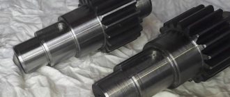
Gears are made integral with the shaft (gear shaft) (Fig. 1, a, b) or made removable if the distance χ from the tooth cavity to the keyway (Fig. 2) is more than 2.5 mn for spur gears and 1, 8 me for conical. The one-piece design increases shaft rigidity and reduces the overall cost of the shaft and gear. The split design allows the gear and shaft to be made from different materials, and if one part breaks, the second one can be left without replacement. In Fig. 1, a shows the design of the gear shaft when the diameter of the tooth cavities df1 exceeds the shaft diameter db.p. (diameter of the bearing flange), which ensures free exit of the tool when cutting teeth. For df1 < db.p. (Fig. 1, b) the output of the cutter lout is determined by drawing along its outer diameter Df, which is taken according to the table. 1 depending on mn and degree of transmission accuracy.
Spur gears with a diameter of up to 400...500 mm (in some cases up to 600 mm) can be forged, stamped, cast or welded.
Structural elements of gear wheels are shown in Fig. 3.
Typical designs of gear wheels and the basic relationships of their elements are given in Fig.
4-8. Forged blanks for gears are used for outer wheel diameter 4.df < 200 mm or for narrow wheels (ψba < 0.2) with diameter da up to 400 mm. The stamping operation is highly productive and brings the shape of the workpiece as close as possible to the shape of the finished wheel. To facilitate filling with metal and releasing from the workpiece, the stamp, and therefore the workpiece, must have radii of curvature r ≥ 5 mm and stamping slopes γ ≥ 5° (Fig. 4). The inner surface of the rim, the outer surface of the hub and the disk surface of stamped wheels are usually not treated. The design of the cast wheel is shown in Fig. 5. Table 1. Values of cutter diameter Df, mm
| Transmission strength degree | Nominal module mn, mm | |||||
| 2…2,25 | 2,25…2,75 | 3…3,75 | 4…4,5 | 5…5,5 | 6…7 | |
| 7 8…10 | 90 70 | 100 80 | 112 90 | 125 100 | 140 112 | 160 125 |
Rice. 1. Design of the shaft - gear Fig. 2. Gear element with keyed connection Fig. 3. Structural elements of wheels: a - cylindrical; b - conical; c - worm Fig. 4. Cylindrical gears with da≤ 500mm: a - stamped; b— forged; dst = 1.6 dv; lst≥ bsubject to the condition lst = (0.8…1.5)dv; δ o= 2.5mn+2, but not less than 8…10 mm; n = 0.5mn for the rim, n for the hub depending on the diameter dв; Dores = 0.5(Do+dst); dop = 15…25 mm; c = (0.2…0.3)b for stamped and c = (0.2…0.3)b for forged wheels Fig. 5. Cast cylindrical gear with da= 400…1000 mm: b ≤ 200 mm dst= 1.6 dв - for steel casting; dst = 1.8 dv for cast iron; lst≥ b subject to the condition lst = (0.8…1.5)dv; δ o= 2.5mn+ 2 ≥ 8 mm; n = 0.5mn for rim n for hub; c = H/5, but not less than 10 mm; S = H/5, but not less than 10 mm; e = 0.8δ o; H= 0.8db; H1= 0.8H; R - inscribed arc of a circle Fig. 6. Banded gear wheel with dв over 600 mm: dst = 1.6 dв - for steel casting; dst = 1.8 dv - for cast iron; lst ≥ b subject to the condition lst = (0.8...1.5) dv; c = 0.15b; δ o= 4mn, but not less than 15 mm; t = δo; e = 0.8δ o; d1= (0.05…0.1) dв; l1= 3d1;b ≥ 300 mm Fig. 7. Welded gear: lst= (0.8…1.5)dв≥ b; dst = 1.6 dv; δ o= 2.5mn, but not less than 8 mm;s = 0.8c; Dores = 0.5 (Do+ dst); dop = 15...20 mm. Seam legs: Ka= 0.5d; Kb = 0.1db but not less than 4 mm. The ribs are welded with a seam Kb Fig.
8. Chevron gear with a groove in the middle: lst = b + a; c = (0.3…0.35)(b + a); δ o= 4mn+ 2; h = 2.5mn; a - depending on the module. For other dimensions see fig. 4, 5 Hub sizes are selected according to the recommendations given below the figures. If possible, the length of the hub lst is taken equal to the width of the wheel crown b, which ensures the smallest width of the gearbox. The ratio of the hub length to the shaft diameter must be at least 0.5. When the ratio is less than 0.8, a shoulder is provided on the shaft, eliminating the end runout of the wheel, against which the end of the wheel hub will be pressed. If, according to the calculation conditions (see calculation of keyed and splined connections) lst> b, then it is advisable to move the hub along the axis of the wheel until one of its ends coincides with the end of the rim (see Fig. 3, a), which makes it possible to cut teeth on two at once wheels. Less commonly (for single-stage gearboxes), wheels are made with a hub protruding in both directions relative to the crown (Fig. 3, c), and teeth can be cut on only one wheel. With the same hub length and ring width, you can cut teeth on several wheels at the same time.
In order to save material, with large wheel diameters, spokes are used instead of a solid disk to connect the hub to the wheel crown. Gear wheels of large diameter (with an outer diameter da≥ 600 mm) are sometimes made with bands (Fig. 6): the crown is forged steel (band), and the wheel center is made of steel or cast iron. The crown mates with the wheel center with a guaranteed interference fit. For greater reliability, screws are placed in the plane of connection between the crown and the center; connections are checked for crushing according to the material of the wheel center: with a steel wheel center [σ] cm≥ 0.3σ t, with cast iron [σ] cm≥ 0.4σ v.i, where σ t is the yield strength; σ v.i is the bending strength of cast iron.
When individually manufactured, wheels are sometimes welded (Fig. 7). With a diameter da≥ 1500 mm, for ease of assembly, the gears are made split - from two halves.
At the ends of the teeth and rim, chamfers of n = 0.5mn are made, the size of which is rounded to the standard value of 1; 1.2; 1.6; 2; 2.5; 3; 4; 5.
Sharp edges at the ends of the hub are blunted with nx 45 chamfers, the size of which is taken depending on the shaft diameter d:
| d, mm n, mm | 20…30 1 | 30…40 1,2 | 40…50 1,6 | 50…80 2 |
| Continuation | ||||
| d, mm n, mm | 80…120 2,5 | 120…150 3 | 150…250 4 | 250…500 5 |
Chevron gears (Fig. differ from other cylindrical wheels by being wider. Most often, chevron gears are made with a groove in the middle, designed for the exit of a hob cutter that cuts teeth. With known cutter sizes, the width of the groove a is determined by drawing. Approximately the size a can be determined depending on module m:
| m, mm a, mm | 1,5 27 | 2 32 | 2,5 37 | 3 42 | 3,5 47 | 4 53 | 5 60 | 6 67 | 7 75 | 8 85 | 10 100 |
The remaining structural elements of the chevron wheels are taken according to the ratios indicated under Fig. 8.
Bevel gears are made forged, stamped, cast or from round bars (Fig. 9-11).
Bevel wheels with an outer diameter of the tooth tips dae < 120 mm are designed as shown in Fig. 9. In the case when the pitch cone angle σ < 30 °, the wheel is made according to Fig. 9, a, at σ < 45 ° - according to Fig. 9, b. If 30° ≤ σ ≤ 45°, both forms can be used. Stamped wheels (Fig. 10, a) are used in mass production. With an external diameter of the apex dae≥ 300 mm, cast conical wheels with stiffeners are also used.
The hub in bevel gears must be positioned so that when the wheel is secured to the mandrel for cutting teeth, a clearance of a> 0.5 mte is provided for the free exit of the tool, where i.e. the outer circumferential module (Fig. 11).
Rice. 9. Bevel gears with dae < 120 mm: a - with δ < 30°; b—at 5 >45°; hub diameter dst = 1.6 dv; lst= (0.9…1.2)dv; δ o= 2.5mn+ 2, but not less than 10 mm; n = 0.5mn Fig. 10. Bevel gears with dae up to 500 mm: a - stamped; b - forged dst = 1.6 dv; lst= (0.9...1.2) dv., but not less than 10 mm; c = (0.1…0.17)Re; n = 0.5mn; The dimensions of Dot and Dot are determined structurally Fig. 11. Fastening the bevel wheel when cutting teeth Fig. 12. Plastic gear with a steel bushing (hub) installed during wheel molding Fig.
13.13. Gear wheel (gear) made of plastic with a steel prefabricated hub. The disks of cylindrical and bevel gears are provided with holes with a diameter of dhole, used for fastening during processing on machines and during transportation. With large hole sizes, they serve to reduce the weight of the wheels, and in cast wheels also to allow the release of casting gases during casting.